Science in daily life: EP11 – Two-Roller Pitching Machine

Hello, everyone! I am Teacher Raccoon. Have any of you ever played baseball before?
Baseball is the national sport of Taiwan, and it is a team sport. When the batter hits the ball thrown by the pitcher with a bat, they can run bases. If they successfully return to home plate, they score a point. To train batters' hitting skills, teams use a machine called a pitching machine. The pitching machine can replace the pitcher in throwing baseballs, preventing fatigue or injury caused by the pitcher throwing for an extended period.
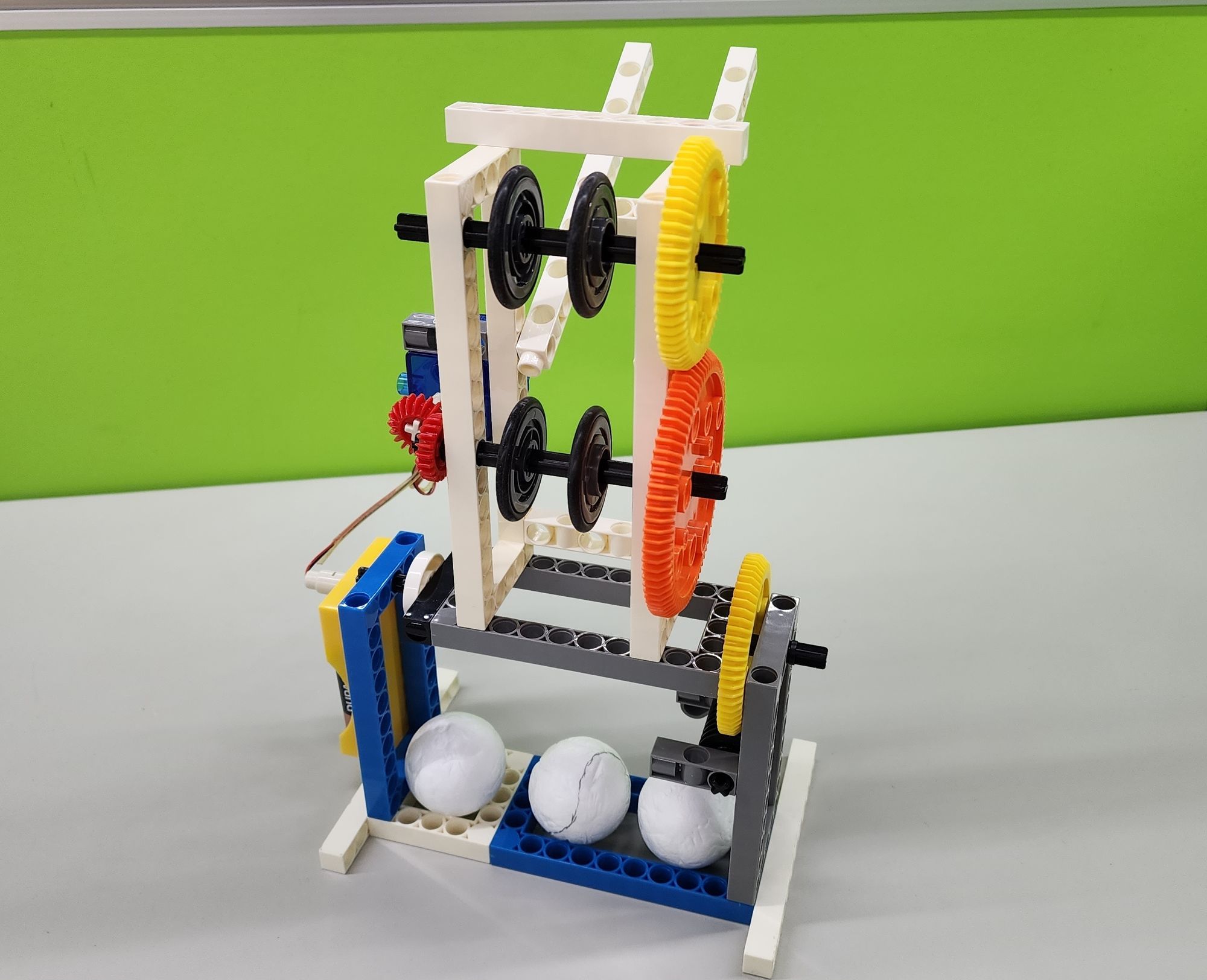
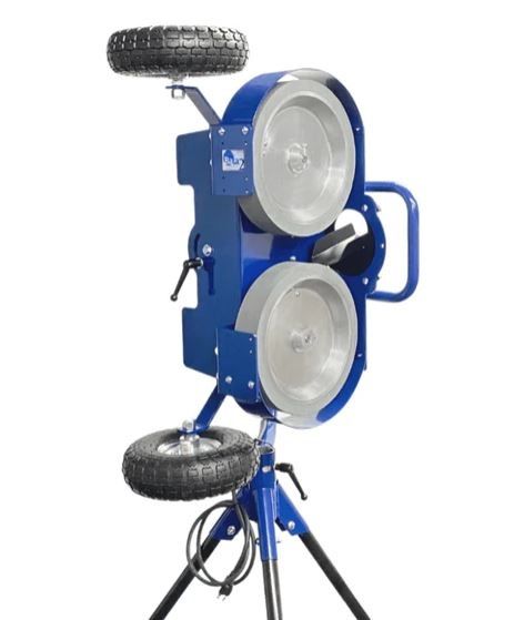
There are many types of pitching machines available in the market. Today, Teacher Raccoon is going to teach you how to make a two-roller type pitching machine. This pitching machine has two rollers, one above and one below, which can spin rapidly. When a baseball passes between the two rollers, it accelerates and flies towards the batter. Now, let Teacher Raccoon guide you step by step on how to make it out!
◆Assembly Steps
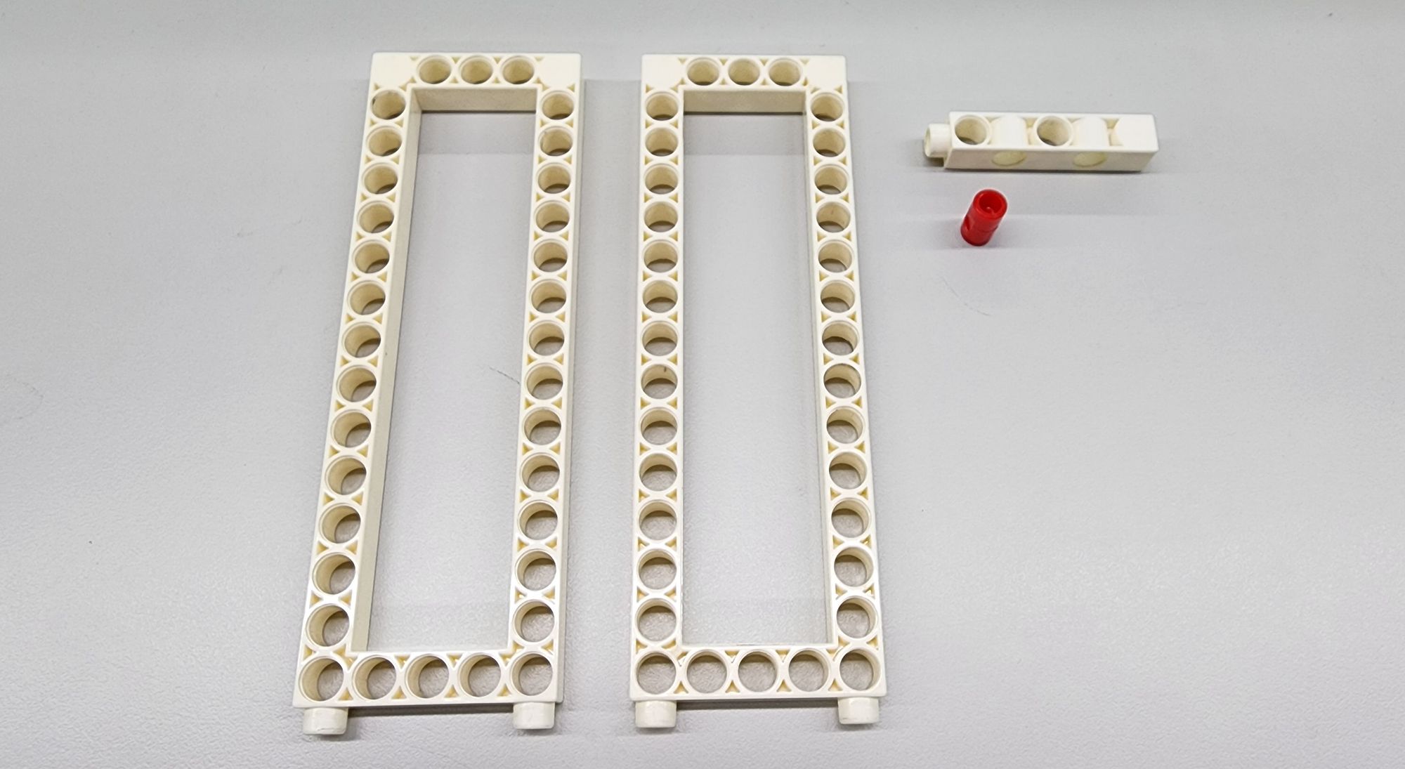
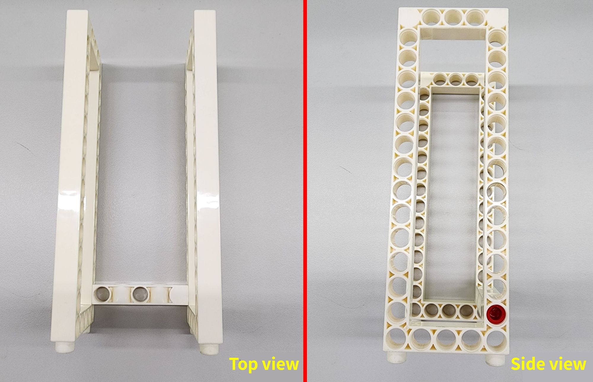
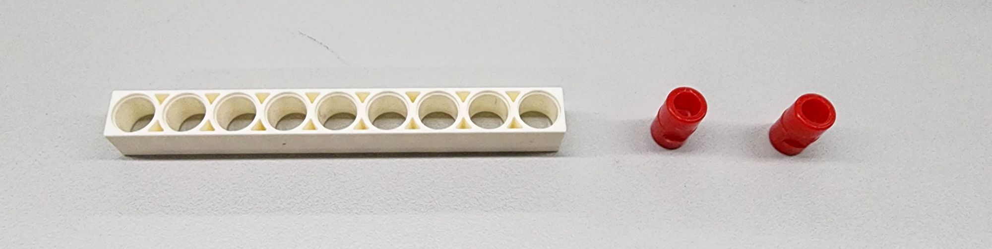
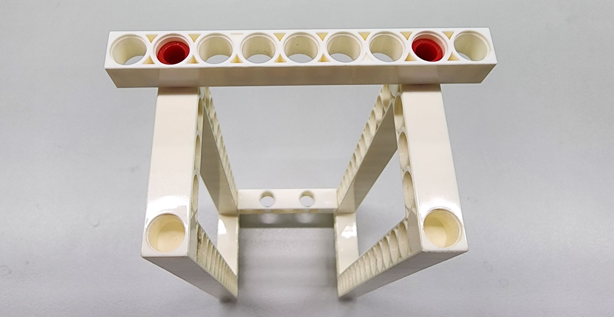
Step 1: We create the main body of the pitching machine. We need to use the C-5×15 FRAME, a C-5 HOLE DUAL ROD, and a C-LONG PEG (as shown in Figure 1). Combine them together accordingly (Figure 2).
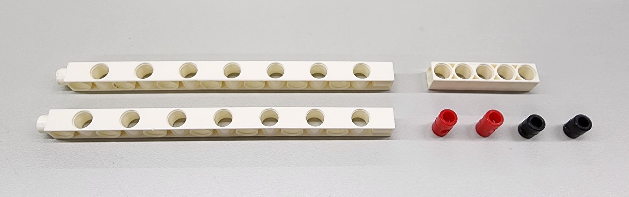
Step 2: We then reinforce the main body of the pitching machine. We mainly use a C-9 HOLE ROD and C-LONG PEG (as shown in Figure 3). Install them onto the main body accordingly (Figure 4).
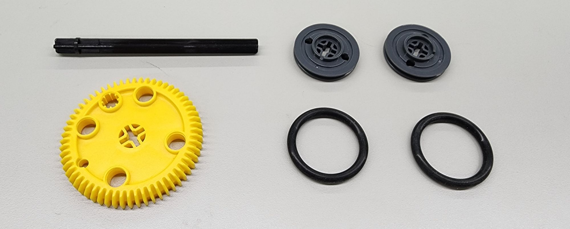
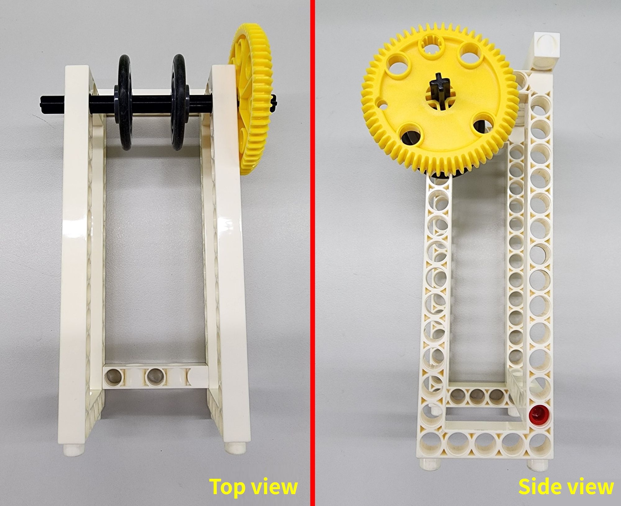
Step 3: We now make the upper roller of the pitching machine by using the C-OD33mm PULLEY, C-OD36 O-RING, C-60T GEAR and C-100mm AXLE Ⅱ(Figure 5). Install them onto the main body of the pitching machine (Figure 6).
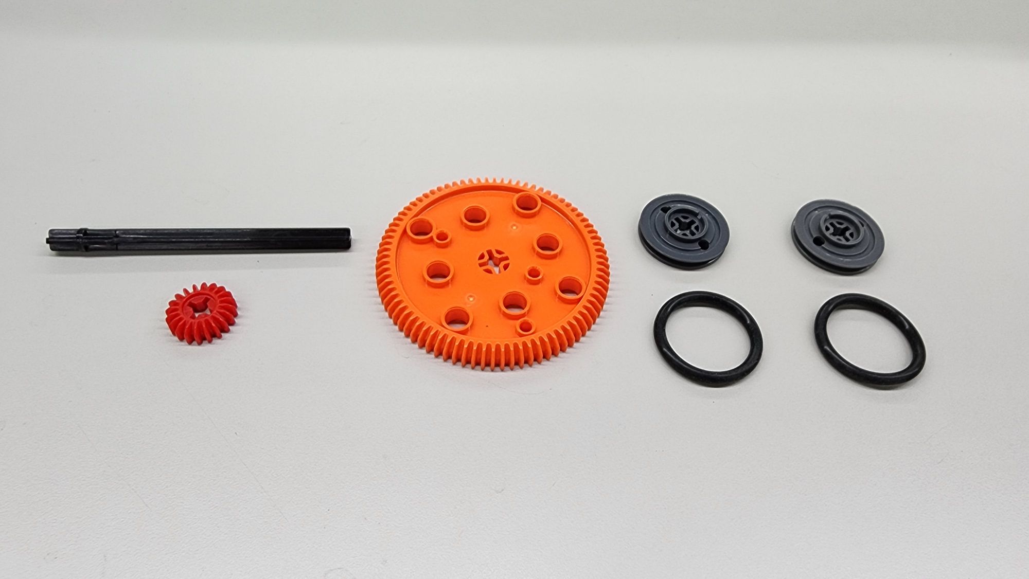
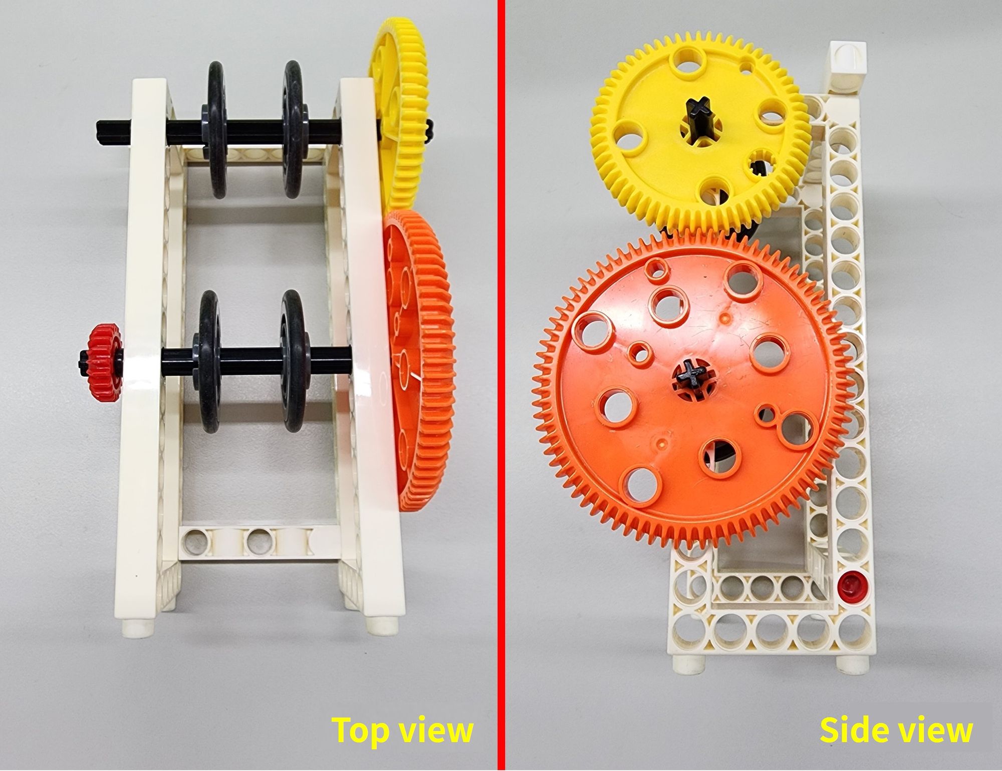
Step 4: We now make the lower roller of the pitching machine by using the C-OD33mm PULLEY, C-OD36 O-RING, C-80T GEAR, C-20T GEAR and C-100mm AXLE Ⅱ(Figure 7). Install them onto the main body of the pitching machine (Figure 8).
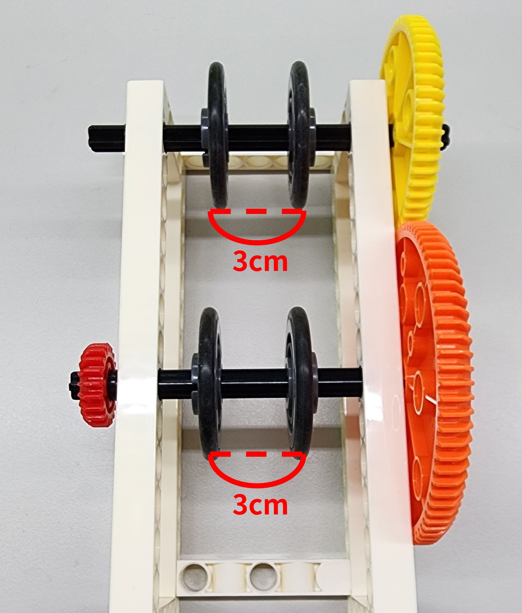
After the installation of the upper and lower rollers, we need to adjust the location of the C-OD33mm PULLEY, making sure that the two C-OD33mm PULLEY on both axle has the 2 cm ~ 3 cm gap (Figure 9), and that the two axle can rotate well. In this way, it can prevent the ball from being stuck between the two sets of rollers, and therefore the ball can be launched successfully.
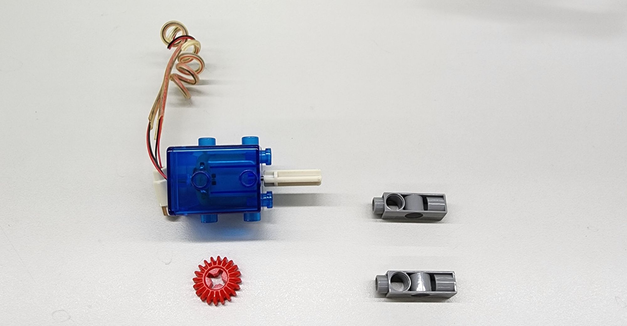
Step 5: We now install the power mechanism for the pitching machine. This requires the use of a C-20T GEAR, two C-3 HOLE DUAL ROD, and C-MOTOR WITH WIRE CONNECTOR (Figure 10) from the GAS AND PNEUMATICS kit (#1238RR). Following the assembly steps, mount the C-3 HOLE DUAL ROD and the C-20T GEAR onto the C-MOTOR WITH WIRE CONNECTOR to complete the assembly of Part A (see Figure 11).

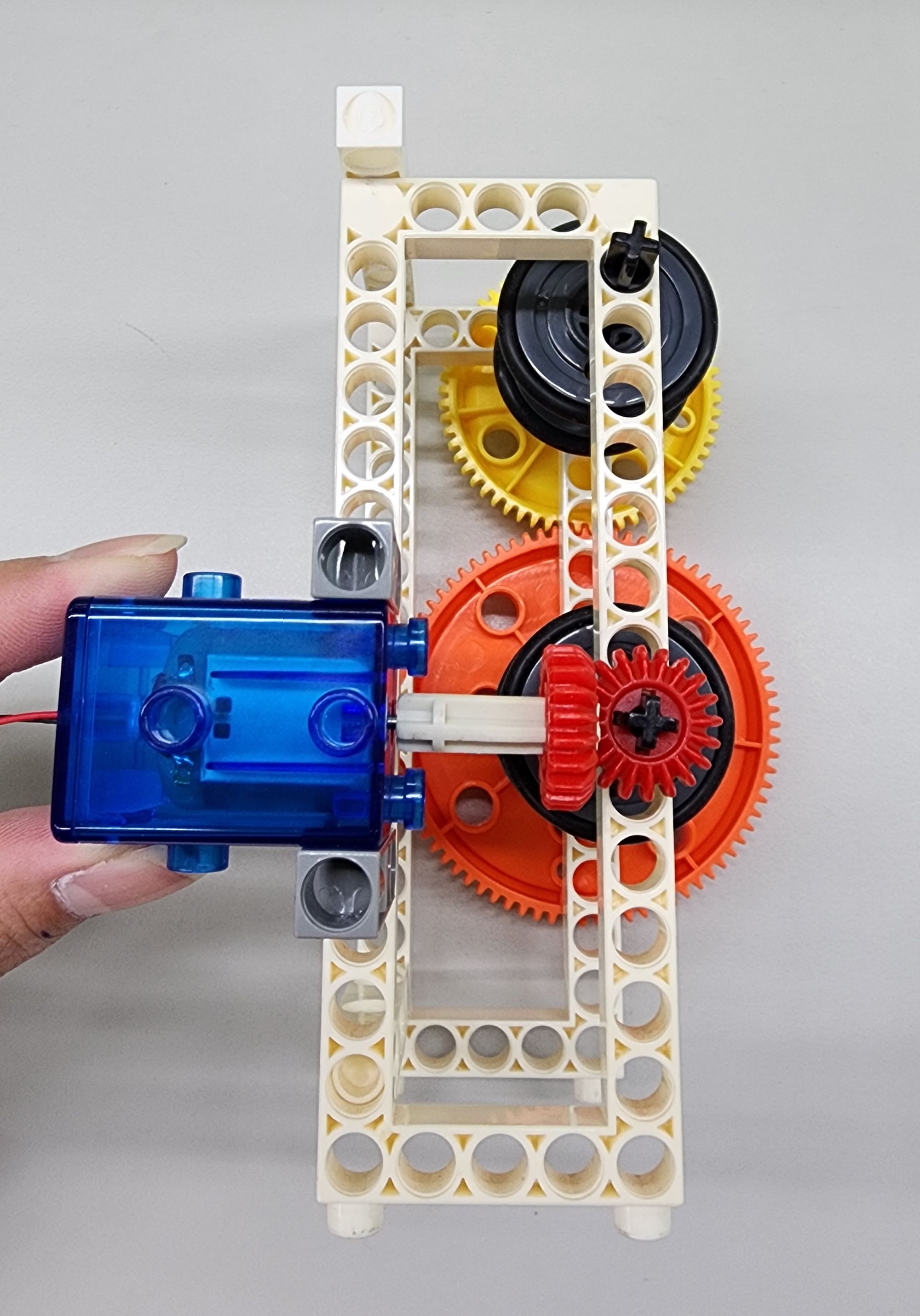
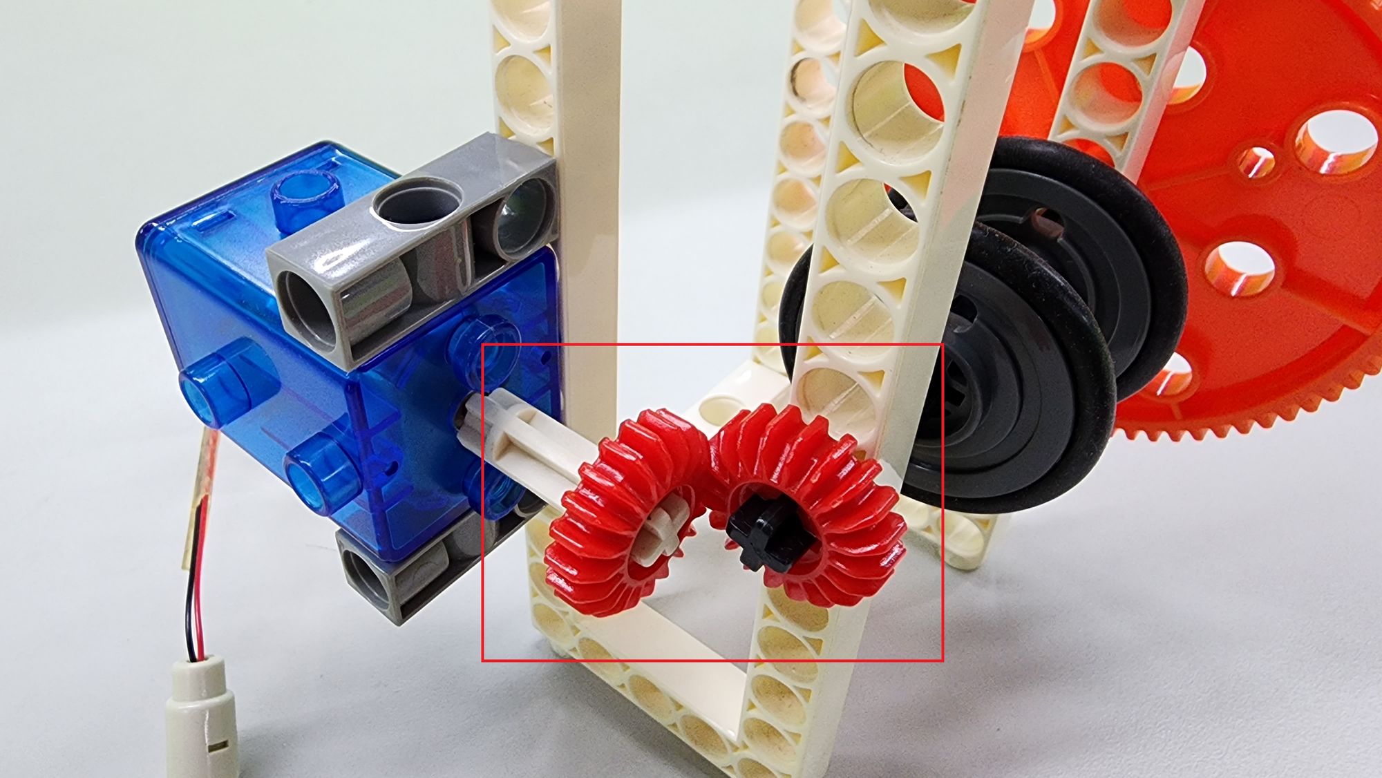
Next, combine the completed Part A with the main body of the pitching machine accordingly (Figure 12). During installation, it is necessary to adjust the positions of the two C-20T GEAR and ensure these two gears mesh successfully (Figure 13).
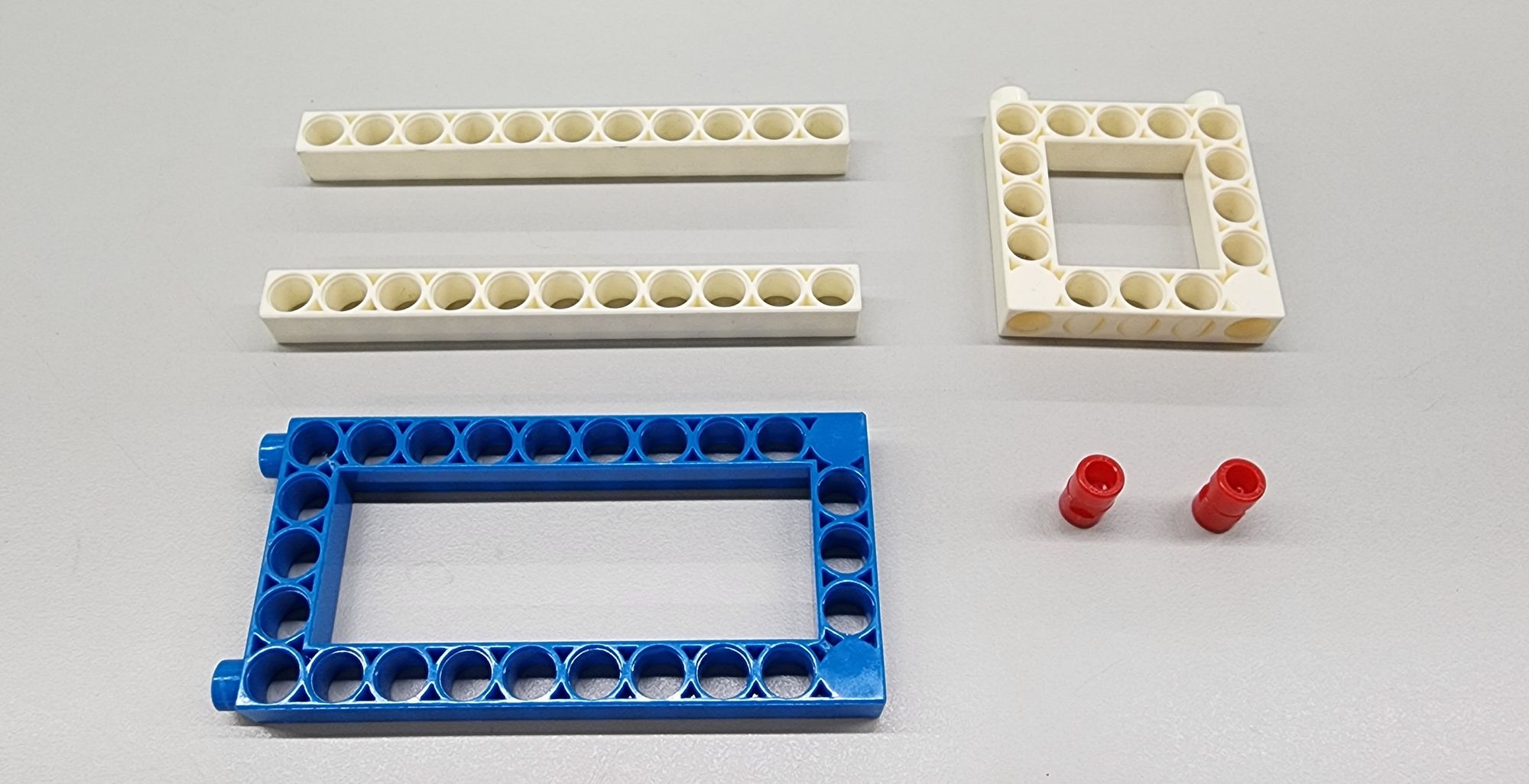
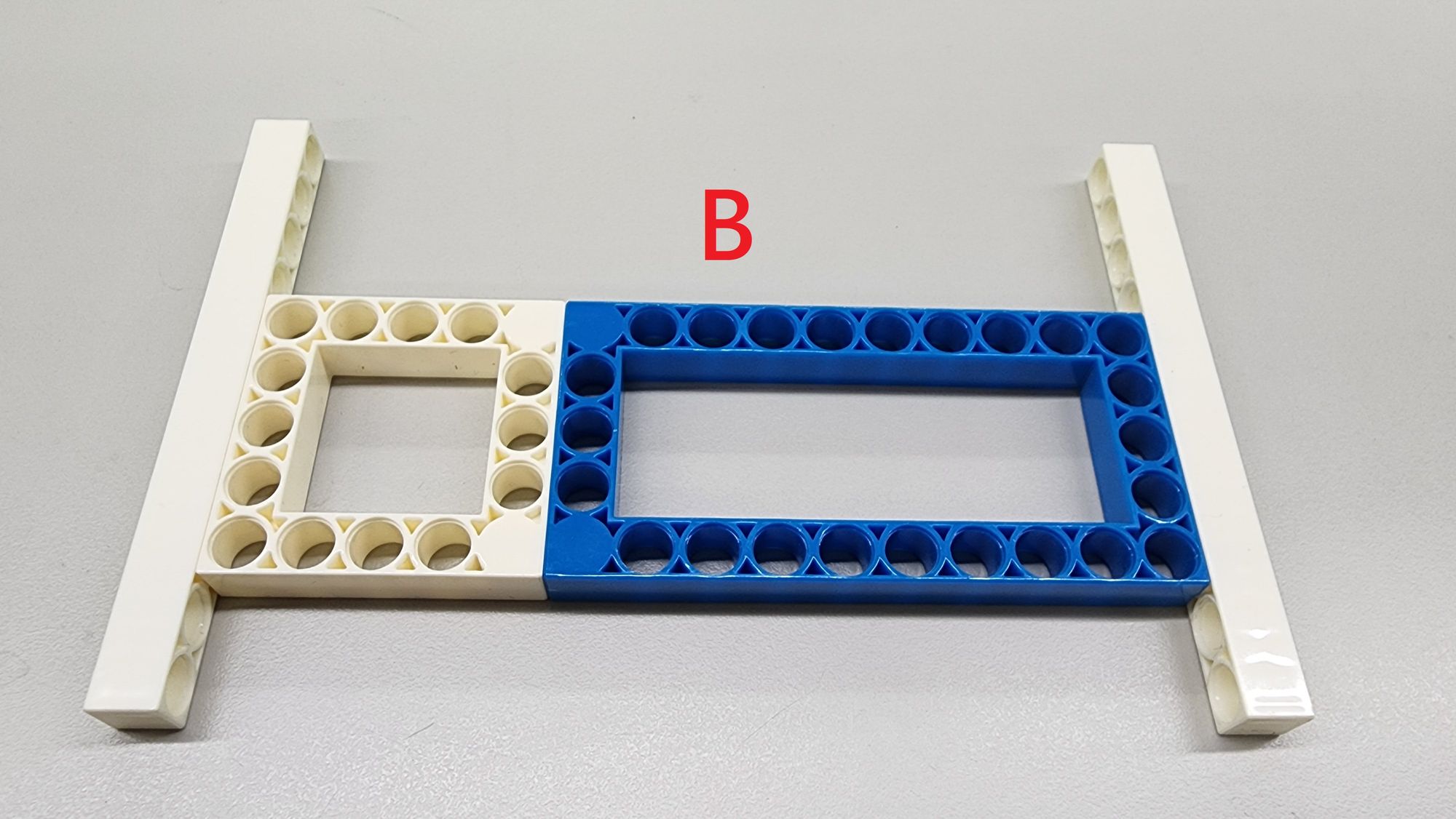
Step 6: We now make the base frame for the pitching machine, requiring the use of a C-5×5 FRAME, a C-5×10 FRAME, two C-11 HOLE ROD, and two C-LONG PEG (Figure 14). Assemble them accordingly to create Part B (Figure 15).
Next, we need to create the rotating platform for the rollers, which is composed of Parts C, D, and E.
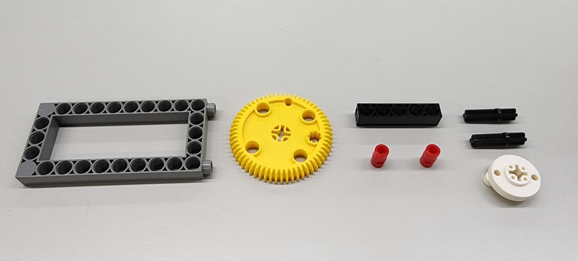
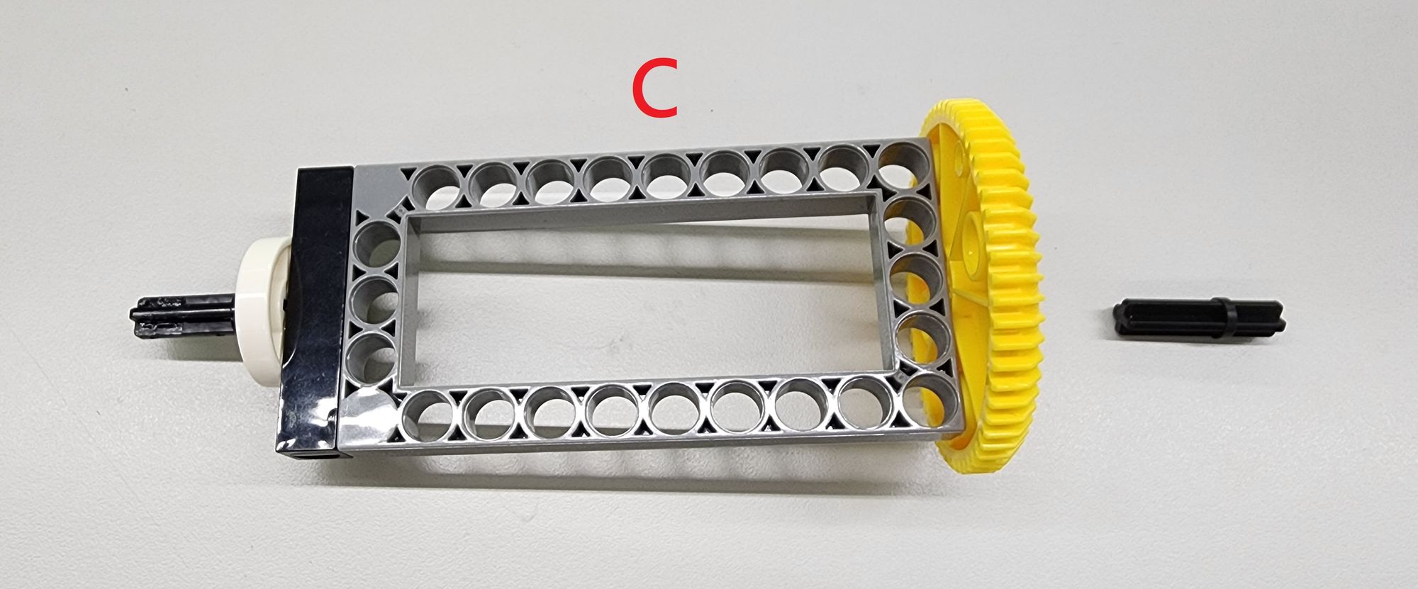
Step 7: For Part C, we need a C-5×10 FRAME, a C-60T GEAR, a C-5 HOLE ROD, two C-LONG PEG, two C-30mm AXLE Ⅱ, and a C-ROD CONNECTOR (Figure 16). Assemble them accordingly to complete the Part C and one C-30mm AXLE Ⅱ aside (Figure 17).
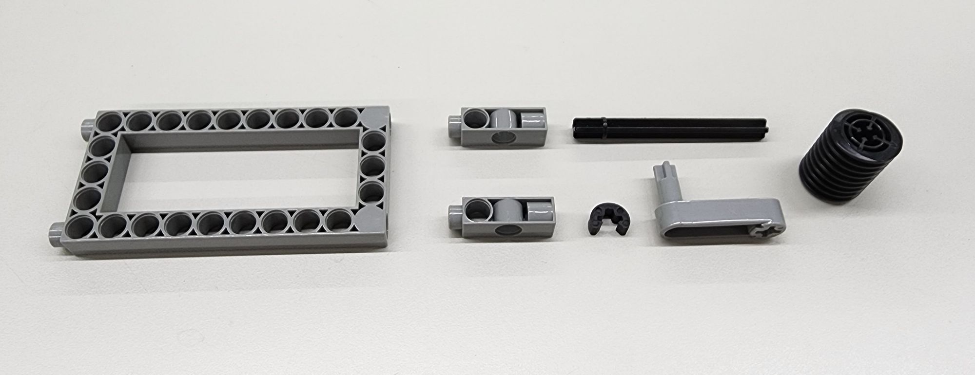
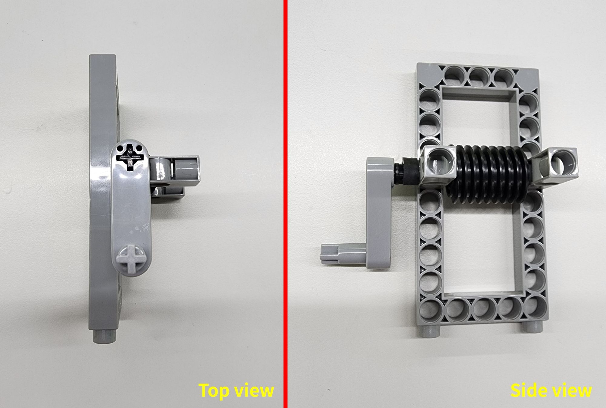
Step 8: The next step is to make Part D, which requires a C-5×10 FRAME, two C-15 HOLE DUAL ROD, a C-70mm AXLE Ⅱ, C-AXLE FIXING, C-CRANK, and C-WORM GEAR (Figure 18). Assemble them accordingly, and complete a worm gear set that can be rotated through the C-CRANK (Figure 19).
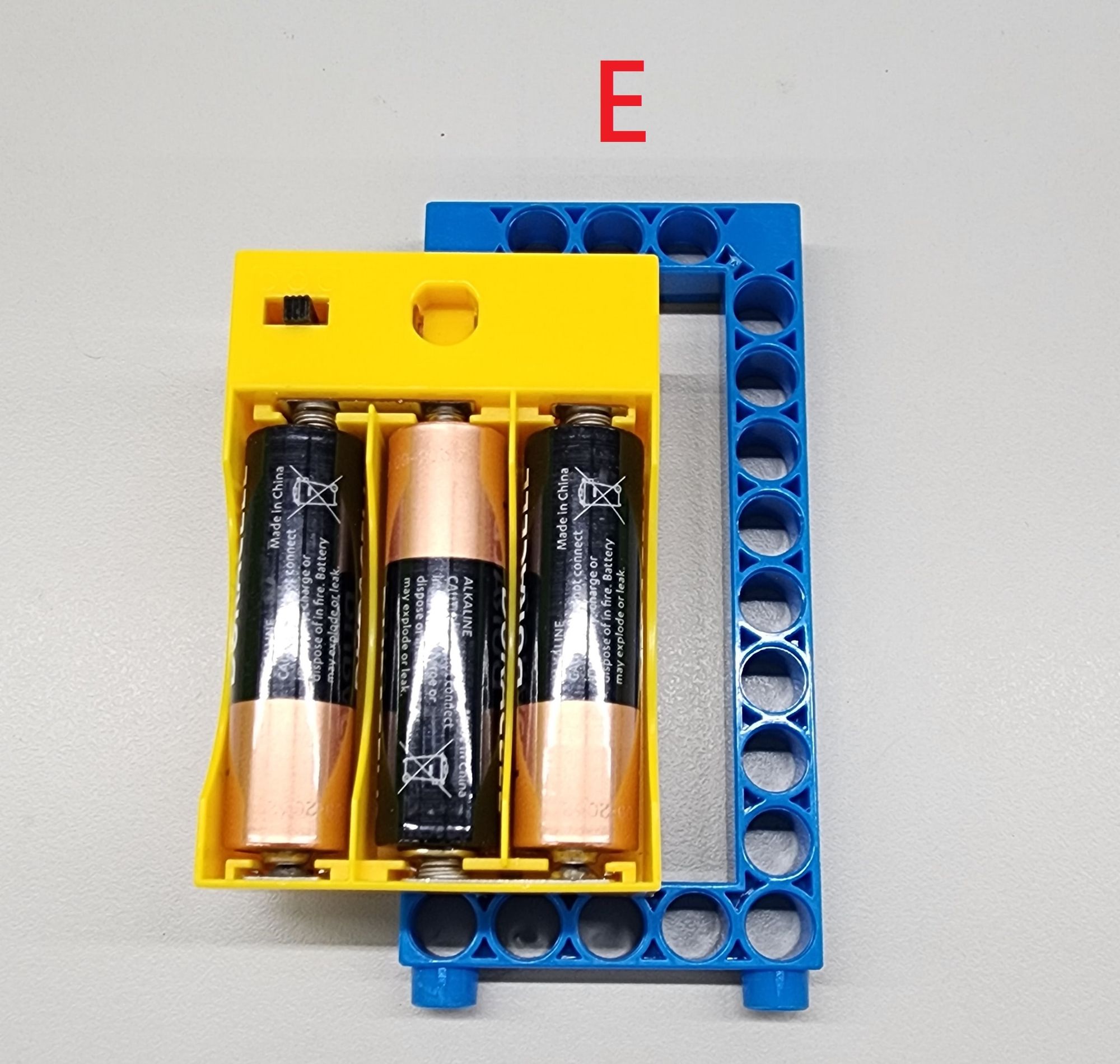
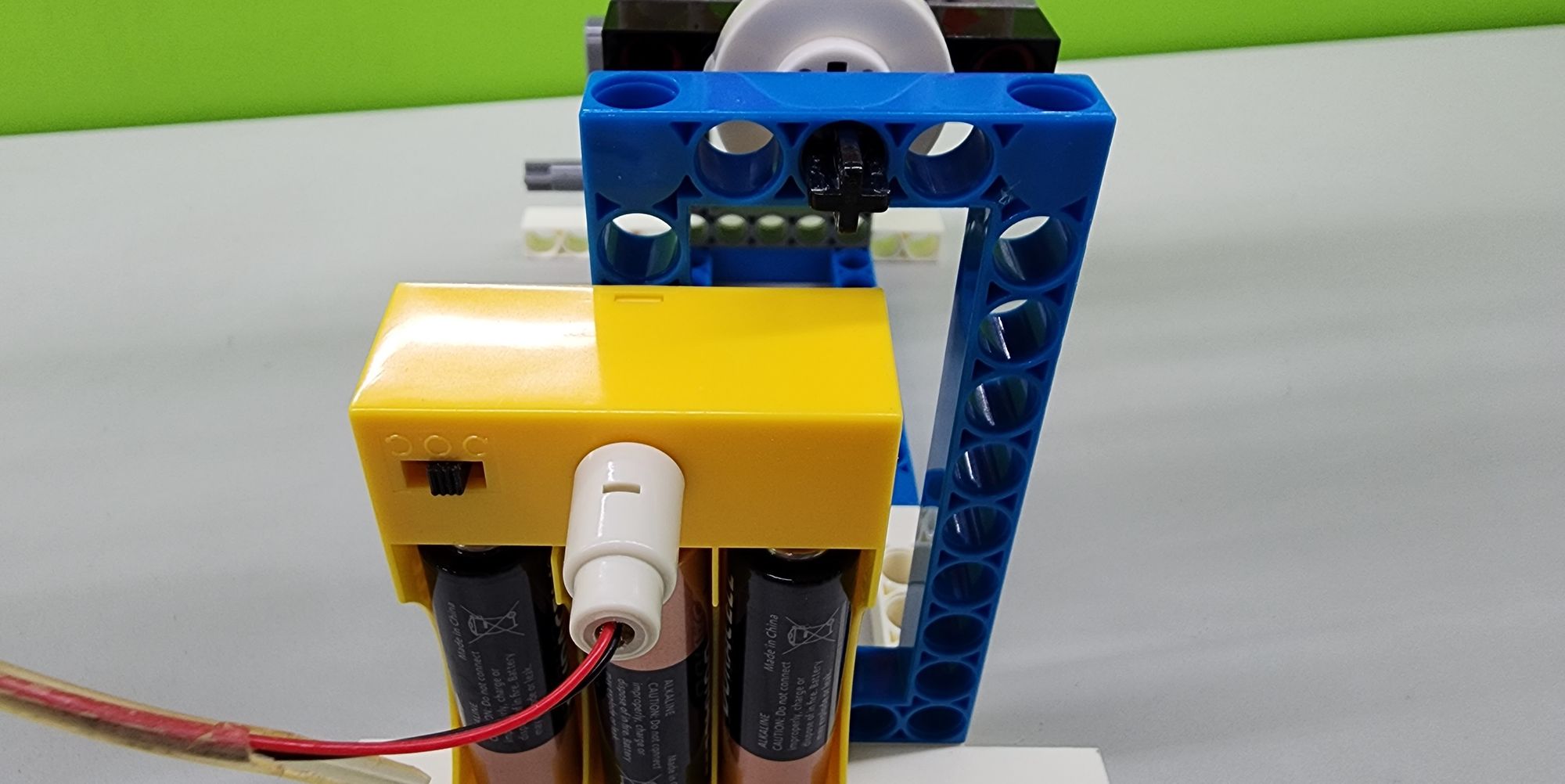
Step 9: We now make the Part E with C-5×10 FRAME, C-4.5V BATTERY HOLDER WITH SWITCH, and three AA alkaline batteries (Figure 20). Combine the C-4.5V BATTERY HOLDER WITH SWITCH with the C-5×10 FRAME, inserting the batteries, to complete the Part E (Figure 21).

Step 10: We now assemble the Parts C, D, and E.
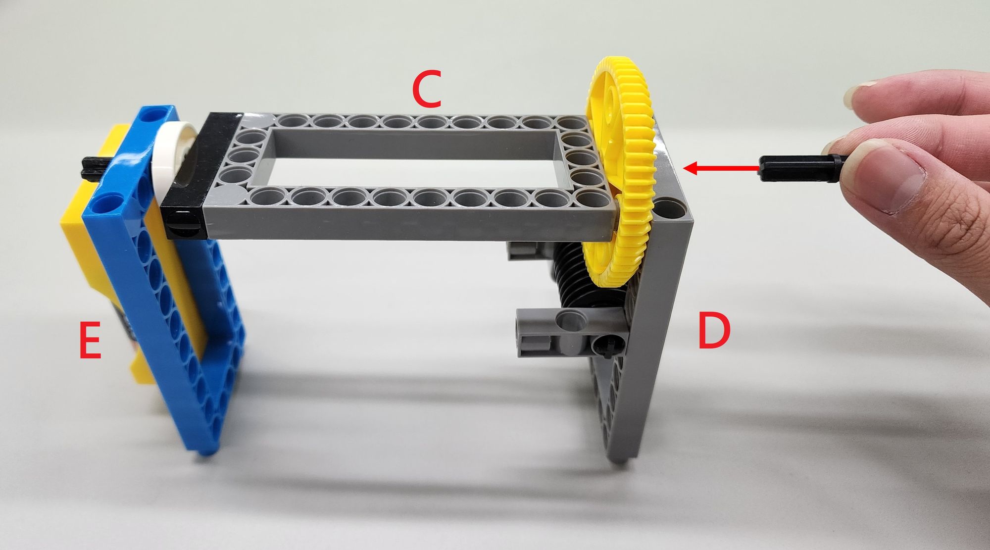
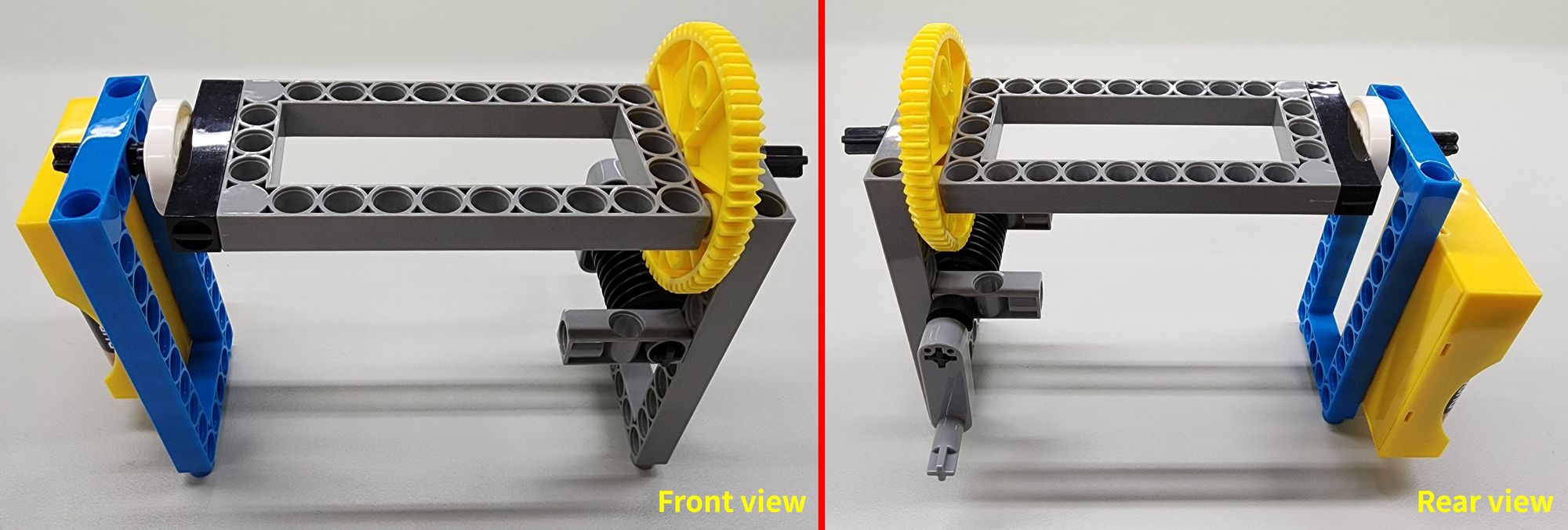
First, thread the C-30mm AXLE Ⅱ from Part C through the holes in Part E, align the C-60T GEAR of Part C with the holes in Part D, and pass it through the extra C-30mm AXLE Ⅱ left from the seventh step (taking note of the direction of the axle's tabs) (Figure 22). Here is the rotating platform (Figure 23).
Step 11: We integrate the base frame with the rotating platform. Install the completed rotating platform on top of Part B (Figure 24).
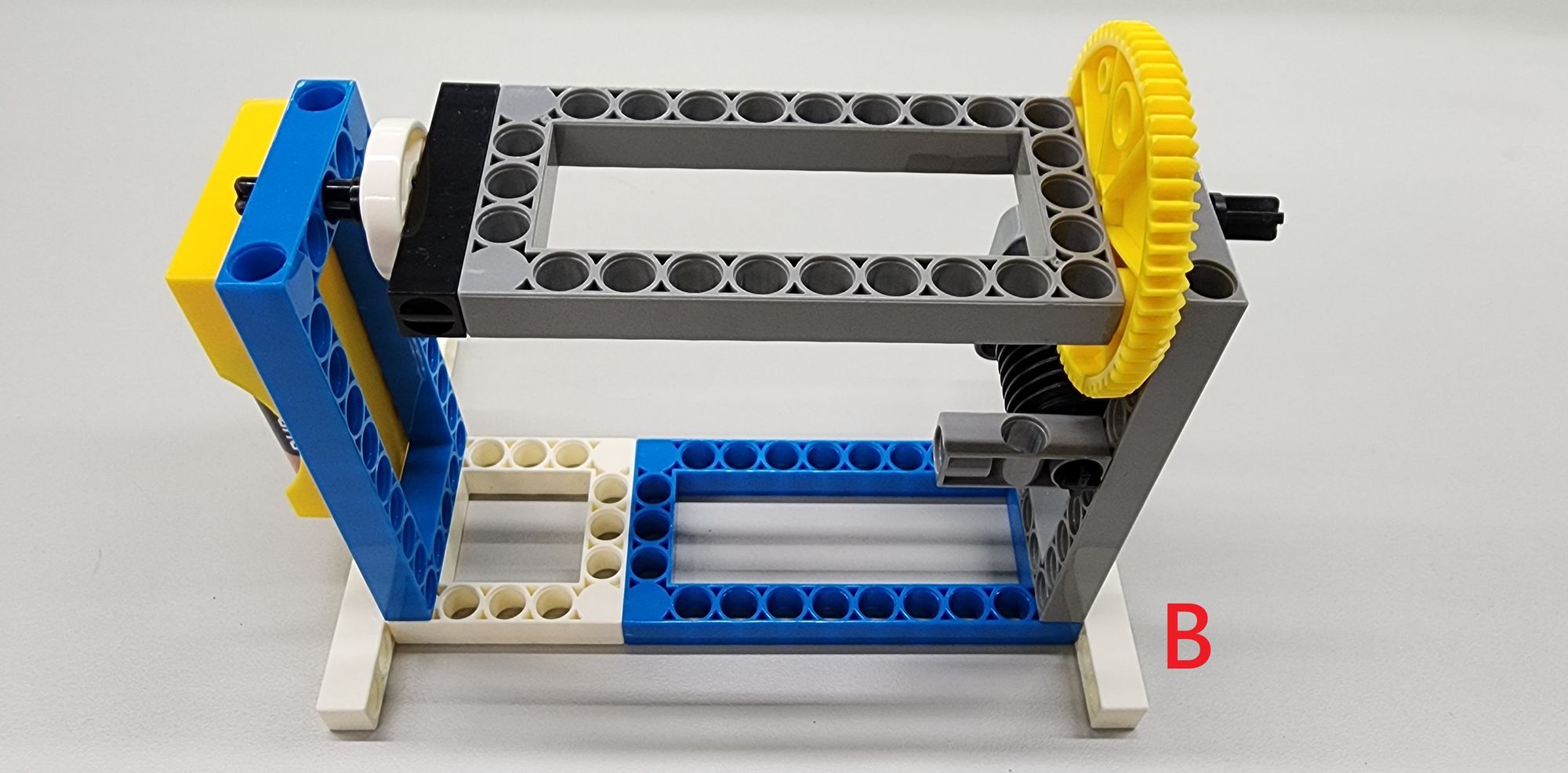
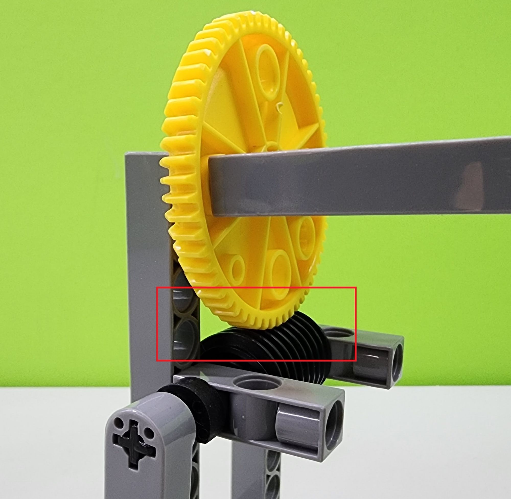
Next, we can test the functionality of the rotating platform. Simply rotate the C-CRANK continuously by hand, and the platform will slowly begin to rotate (Video 1). If the platform does not rotate, check if the C-60T GEAR and C-WORM GEAR are installed correctly. The platform operates correctly only when the C-60T GEAR and C-WORM GEAR mesh together (Figure 25).
Step 12: We now integrate the main body of the pitching machine with the rotating platform, installing the completed main body onto the platform (Figure 26), and mounting the connector of the C-MOTOR WITH WIRE CONNECTOR onto the terminals of the C-4.5V BATTERY HOLDER WITH SWITCH (Figure 27).
Step 13: We now make the track for the pitching machine, using the C-15 HOLE DUAL ROD, C-5 HOLE ROD, C-LONG PEG, and B-SHORT PEG (Figure 28). Assemble them accordingly to create the Part F (Figure 29).
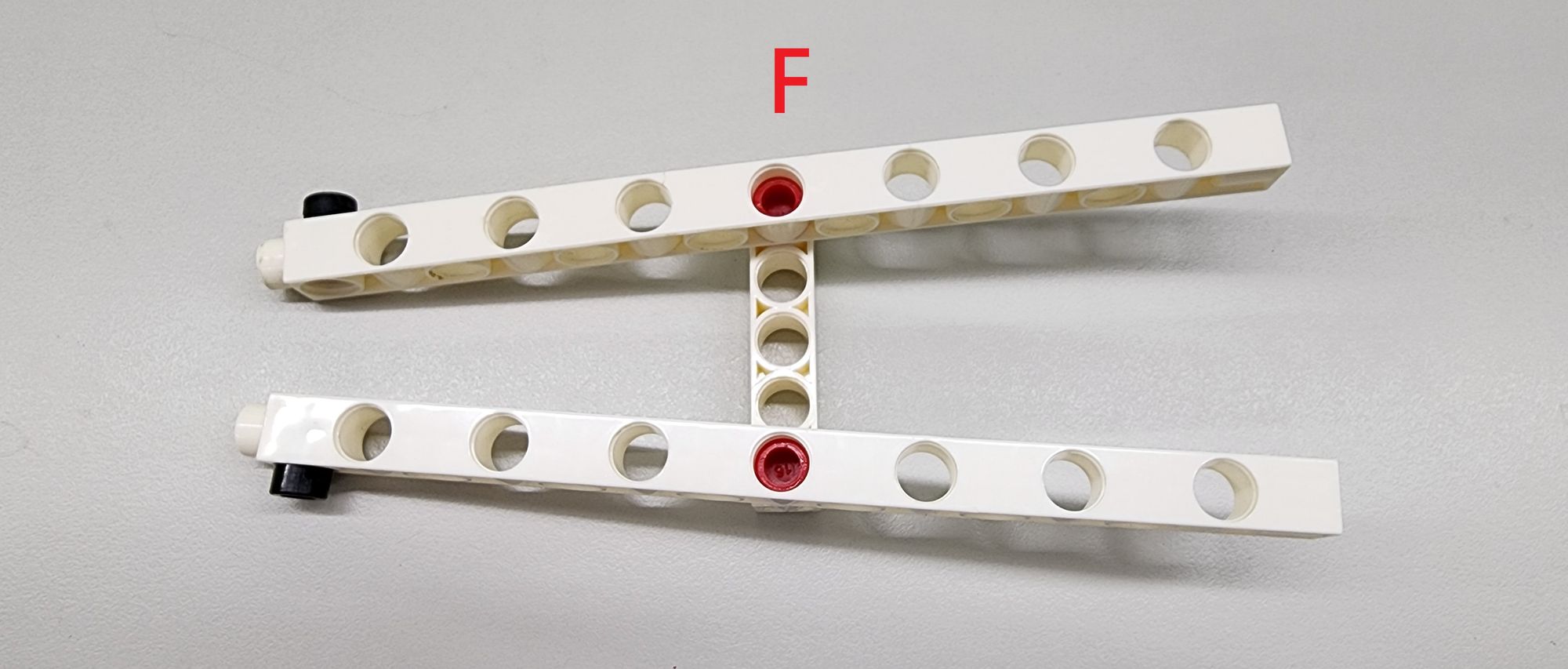
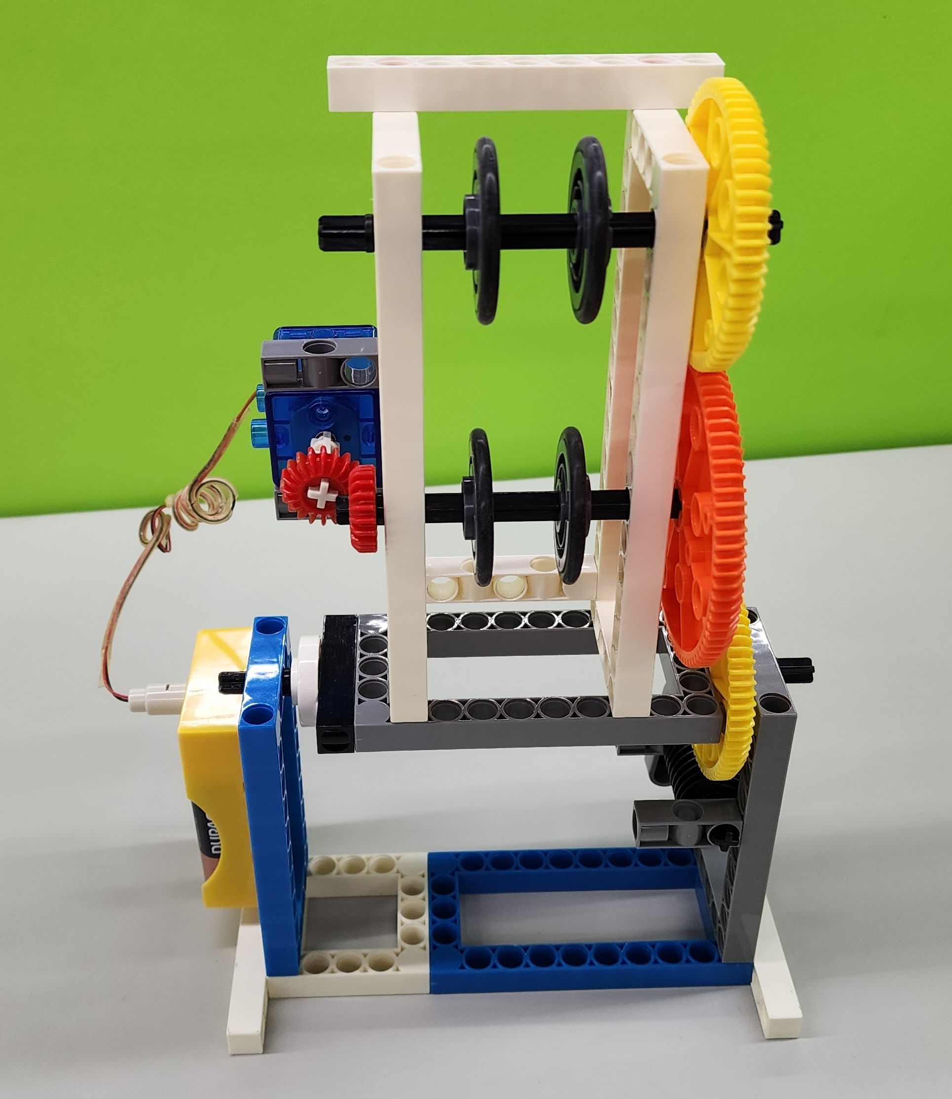
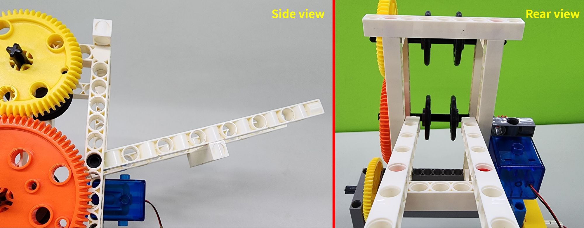
Finally, install the completed Part F at the rear of the body (Figure 30), and adjust the angle of the C-15 HOLE DUAL ROD to ensure that the baseball can smoothly roll between the two sets of OD33mm PULLEY. The model is now complete! (Figure 31)
◆ Model Operation
Now let's operate the pitching machine!
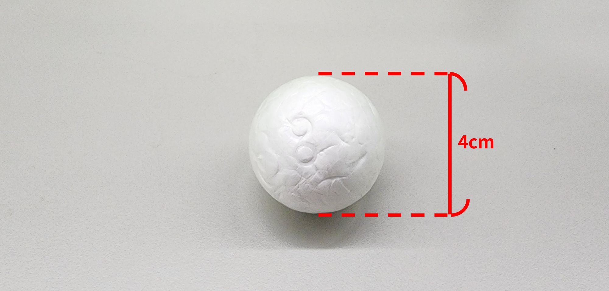
First, we need to prepare the baseball for tossing. Here, Mr. Raccoon chose regular Styrofoam balls with a diameter of approximately 4 cm (Figure 32). However, you can use ping pong balls or the 40mm BALL(7330-W11-M1B) from the Gigo Creative Lab .
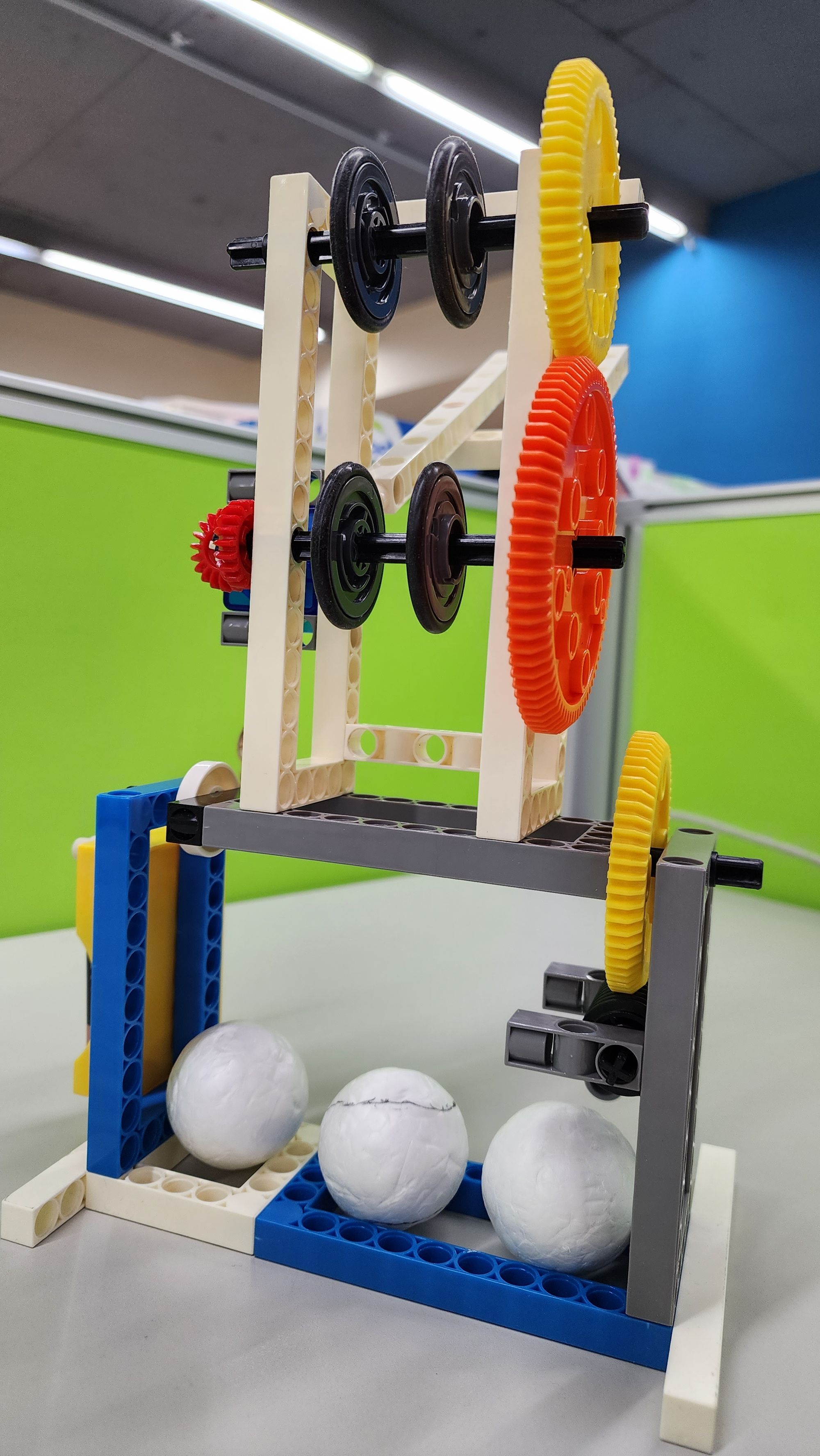
To begin, we need to switch on the C-4.5V BATTERY HOLDER WITH SWITCH and ensure that the rotation direction of the two sets of C-OD33mm PULLEY is forward-facing to launch the Styrofoam ball. Next, place the Styrofoam ball onto the track. As the Styrofoam ball rolls along the track into the main body, it will be accelerated by the high-speed rotation of the C-OD36 O-RING and then launched. You can also turn the C-CRANK to adjust the launching angle using the rotation of the platform (00:16~00:22). Let's be little pitchers together and find the optimal launching angle for the farthest throw! (Video 2)!
◆ Troubleshooting
If your fails to launch the Styrofoam ball, you can try the following solutions:
1. Use brand new AA alkaline batteries.
2. Check the engagement of the C-20T GEAR; either too tight or too loose may cause launching failure.
3. Adjust the positions of the C-20T GEAR, C-60T GEAR, and C-80T GEAR on the C-100mm AXLE Ⅱ; if the gears are mounted too tightly and rub against the C-5×15 FRAME, it will affect the rotation speed of the C-100mm AXLE Ⅱ.
4. Ensure that the distance between the upper and lower sets of C-OD33mm PULLEY is between 2 to 3 cm; either too close or too far may result in launching failure.
5. Use a cloth dampened with water to wipe away dust from the C-OD36 O-RING; dust reduces the friction between the Styrofoam ball and the C-OD36 O-RING, affecting the launching effect.
◆ Conclusion
Through the construction of the pitching machine model, we have discovered various factors that can affect the effectiveness of launching, such as the spacing between C-OD33mm PULLEY, friction between the C-OD36 O-RING and the ball, launching angle, choice of different types of balls, etc. Through experimentation, we can gradually determine the optimal configuration for each factor and strive to achieve the fastest or farthest ball launch possible! You can also try making a target board and see whose ball launcher can hit the Jiugongge baseball net most accurately.
That's all for today's sharing. If you enjoyed this article, please don't forget to share it enthusiastically. Until next time, goodbye.
◆ Scientific Principles
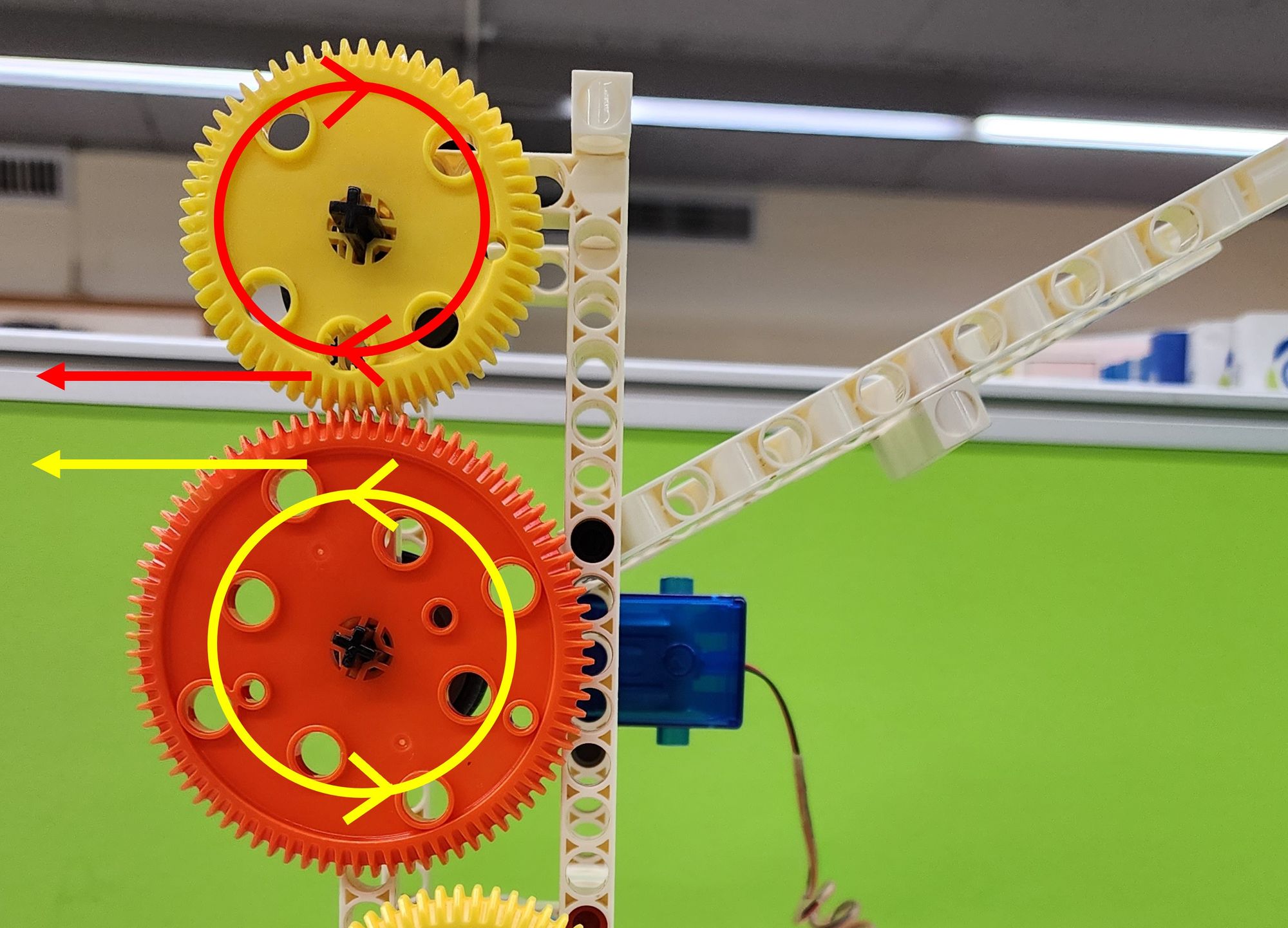
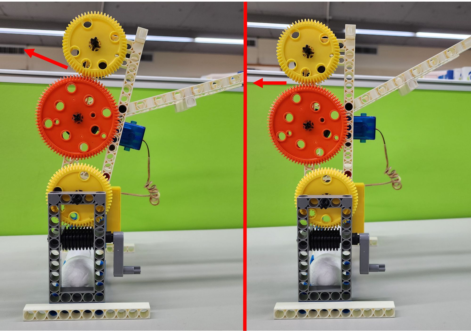
The ball launcher model utilizes the scientific principles of gear transmission, worm gear transmission, and friction. Firstly, when the C-60T GEAR, and C-80T GEAR engage, their rotation directions are opposite, allowing the Styrofoam ball in the middle to be shot in the direction consistent with both gears (Figure 33). When we turn the C-CRANK, the C-WORM GEAR (worm) drives the rotation of the C-60T GEAR (worm wheel), thereby changing the launching angle of the ball launcher (Figure 34). Friction comes into play between the C-OD36 O-RING and the Styrofoam ball, converting the centrifugal force generated by the gear rotation into the power to launch the Styrofoam ball. If kids are interested in other projectile launchers, they can also refer to Teacher Raccoon's another article:Science in Science in daily life: EP3- Money Blaster.
◆Curriculum
K-2-ETS1-1 Engineering Design
K-PS2-1 Motion and Stability: Forces and Interactions
3-PS2-1. Plan and conduct an investigation to provide evidence of the effects of balanced and unbalanced forces on the motion of an object.
◆Reference
 Contributors to Wikimedia projects
 Contributors to Wikimedia projects
 Contributors to Wikimedia projects
 Contributors to Wikimedia projects
 Kevin King
Please sign in to vote.