Science in daily life: EP9 – Umbrella

Hello, everyone! I am Teacher Raccoon. Taiwan is located between tropical and subtropical high pressures. Therefore, every summer, the plum rain and typhoons bring abundant rainfall to Taiwan. If you don't want to end up drenched like a wet chicken, it's a good idea to cultivate the habit of carrying an umbrella with you wherever you go.
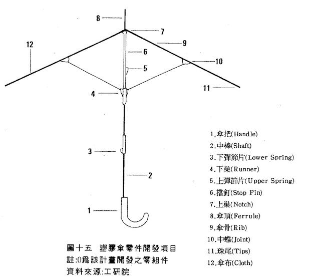
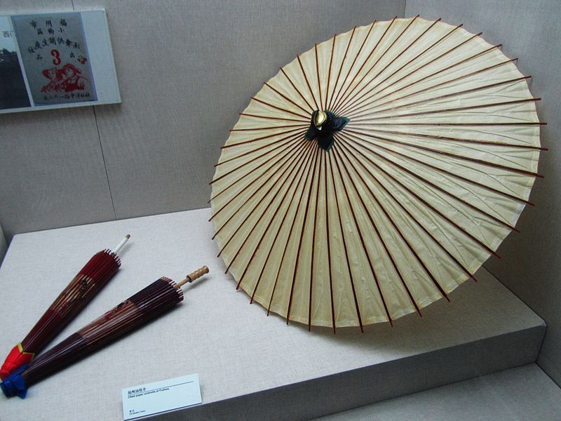
The umbrella is an invention designed to shield against rain, with its origins tracing back to ancient times. One of the most representative examples is the oil-paper umbrella from the Tang Dynasty. It was constructed with bamboo ribs and utilized paper soaked in tung oil as the umbrella fabric. As time has progressed, the durability and functionality of umbrellas have evolved. In addition to using metal umbrella ribs and plastic umbrella fabric, features such as fold ability and automatic retraction have been developed. Now, let Teacher Raccoon guide you through the steps of making an umbrella!
◆Assembly Steps
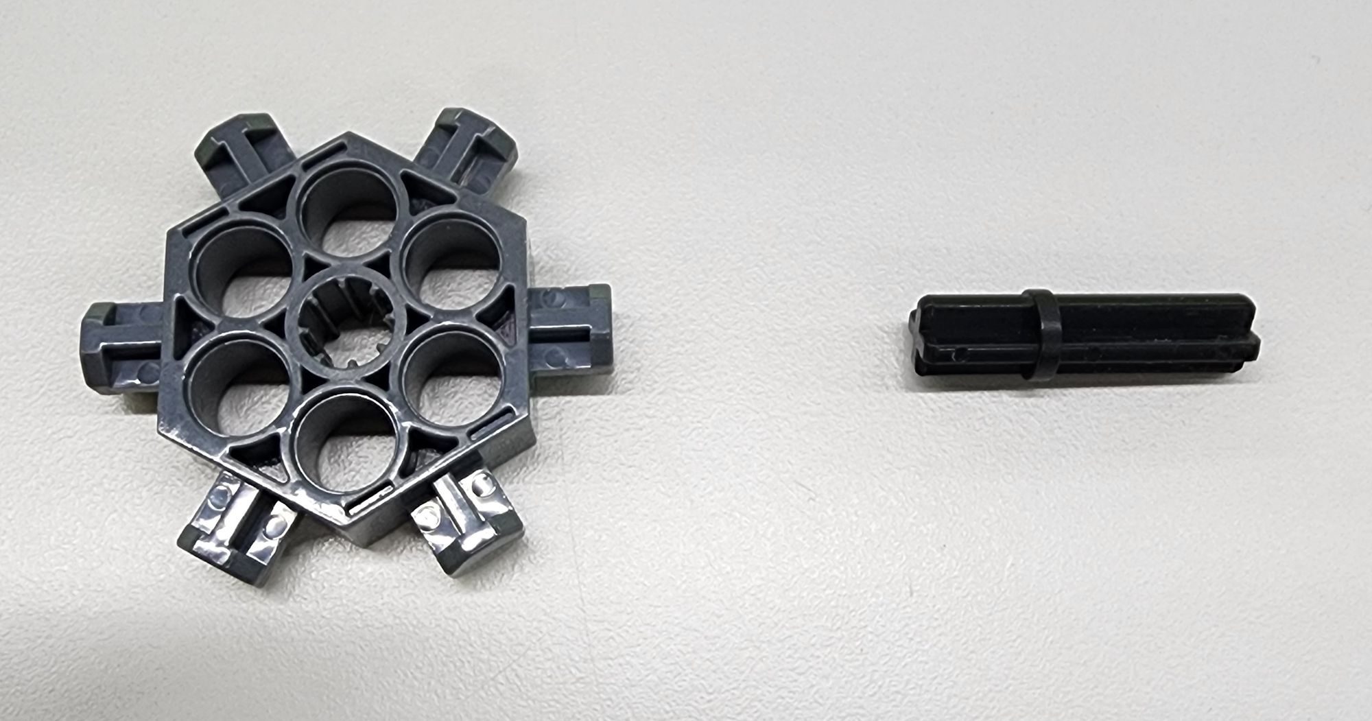
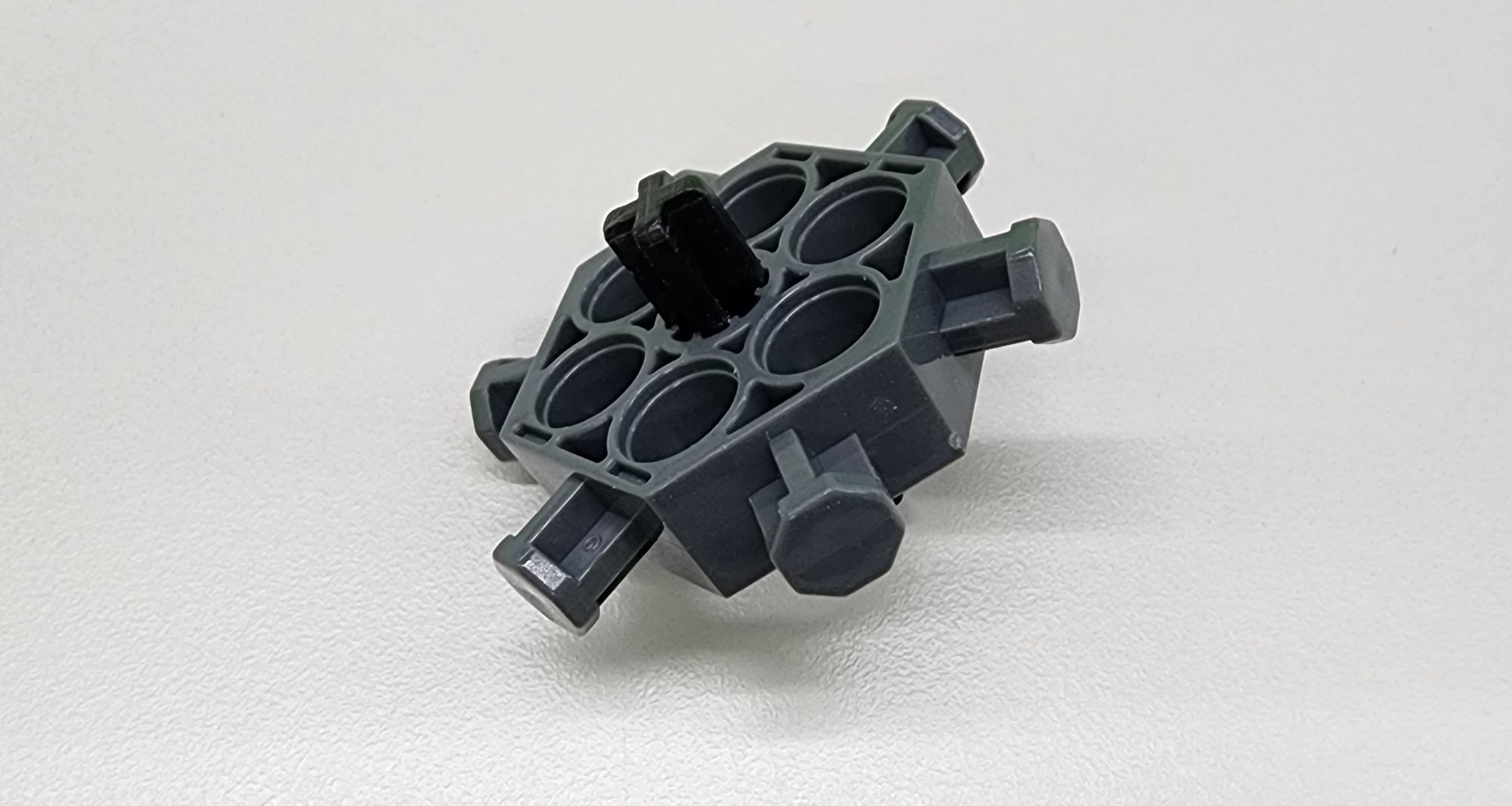
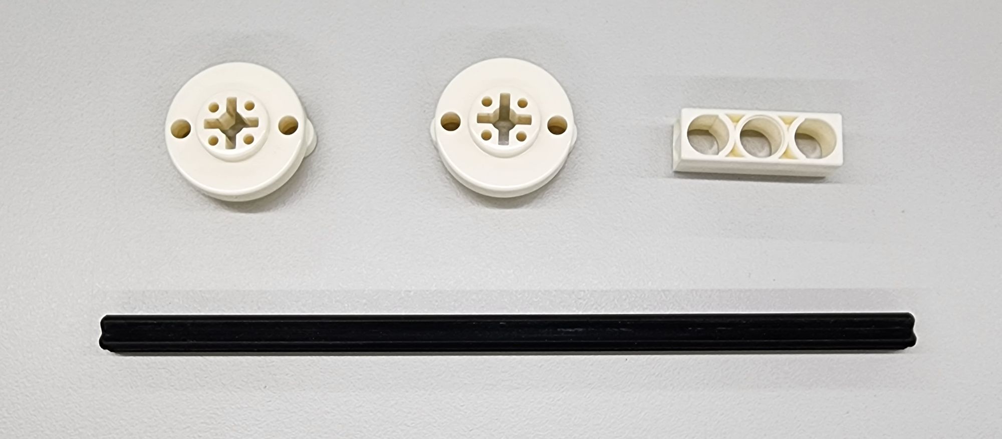
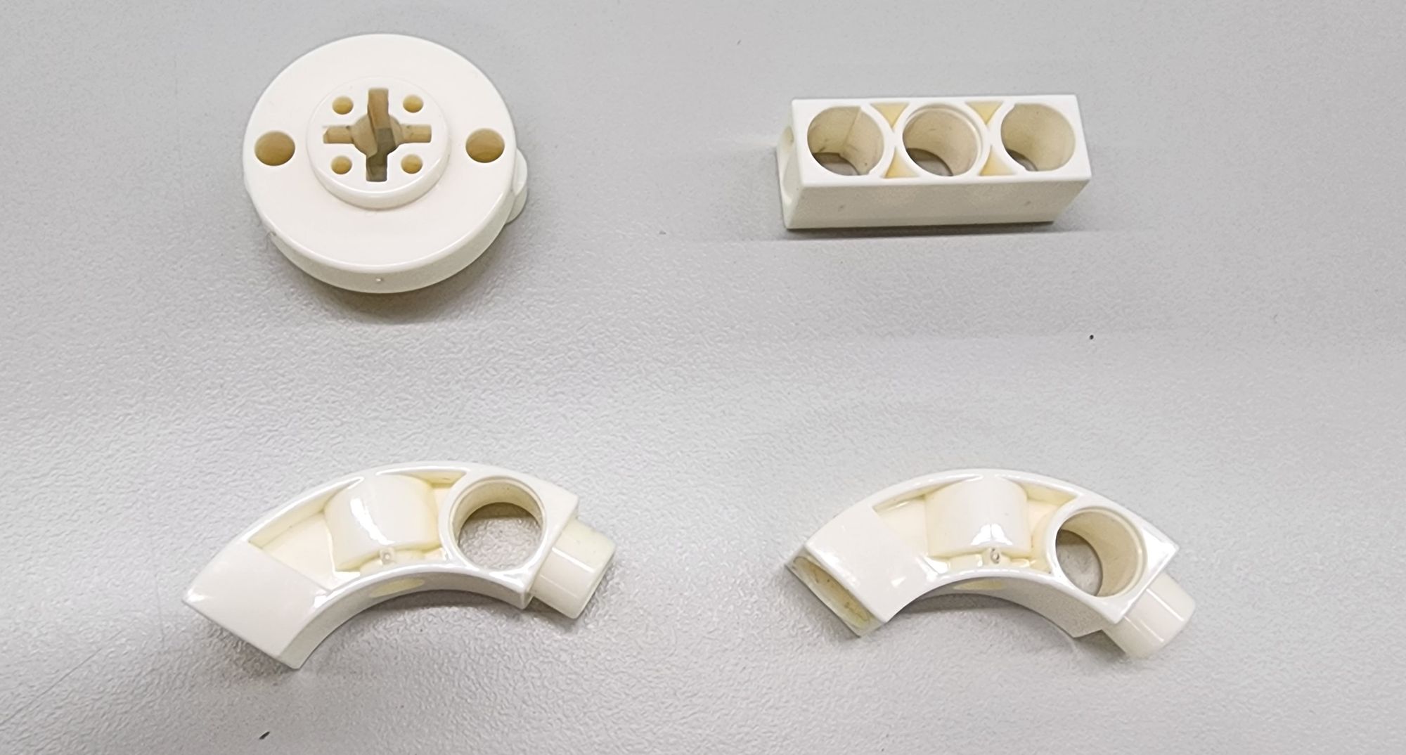
Step 1: Let's start making the Notch and Ferrule. We will need to use the C-30mm AXLE Ⅱ and the C-6-PIN HUB CONNECTOR (7445-W10-A1S) (Figure 1), combine them accordingly (Figure 2).
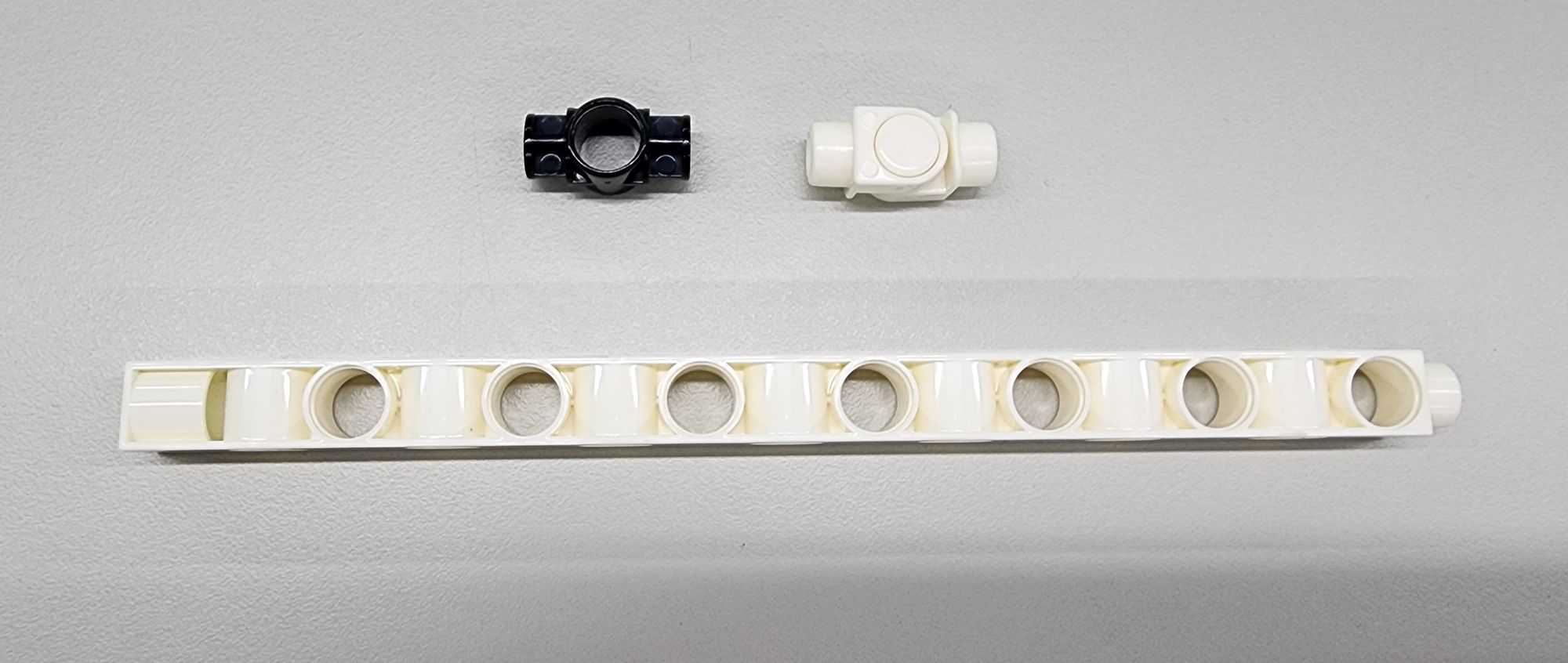
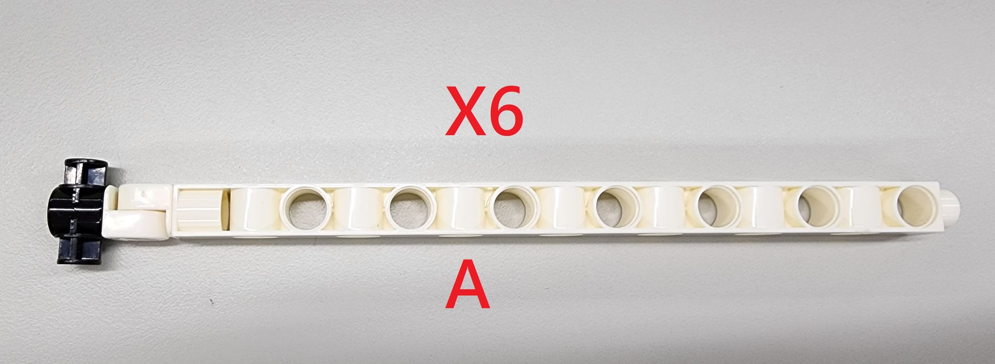
Step 2: We now make the umbrella Ribs. We'll primarily use the C-HINGE, C-1 HOLE CONNECTOR, and C-15 HOLE DUAL ROD (Figure 3). Assemble them to create the part A. Since our umbrella has a total of six ribs, we need to make six sets of part A in total (Figure 4).
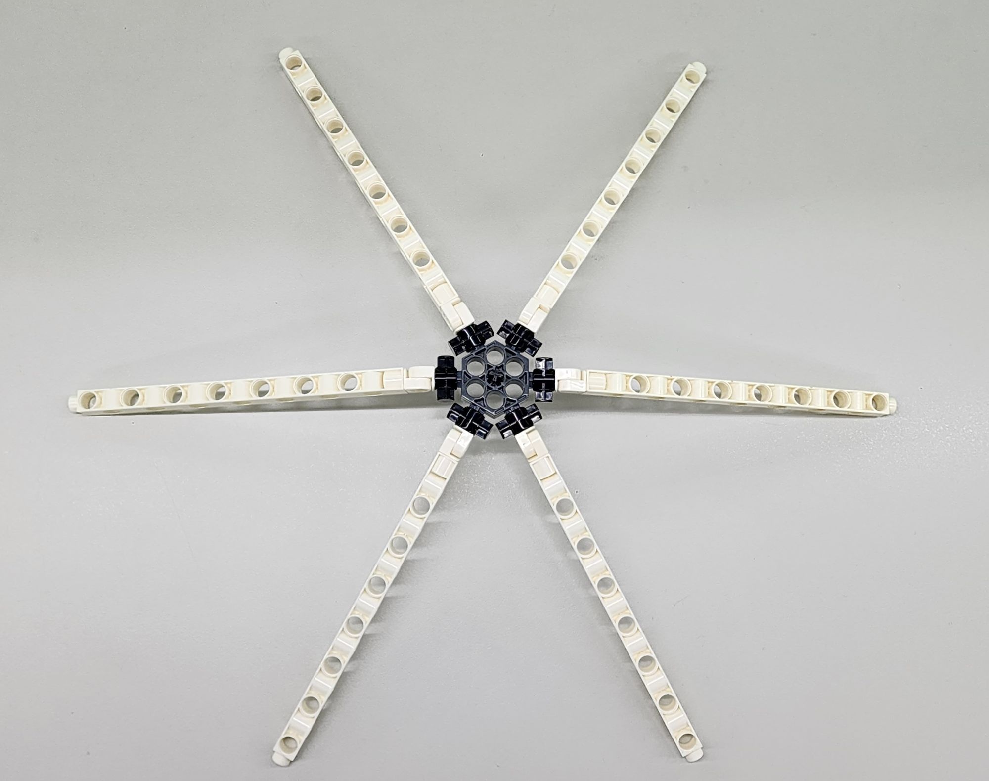
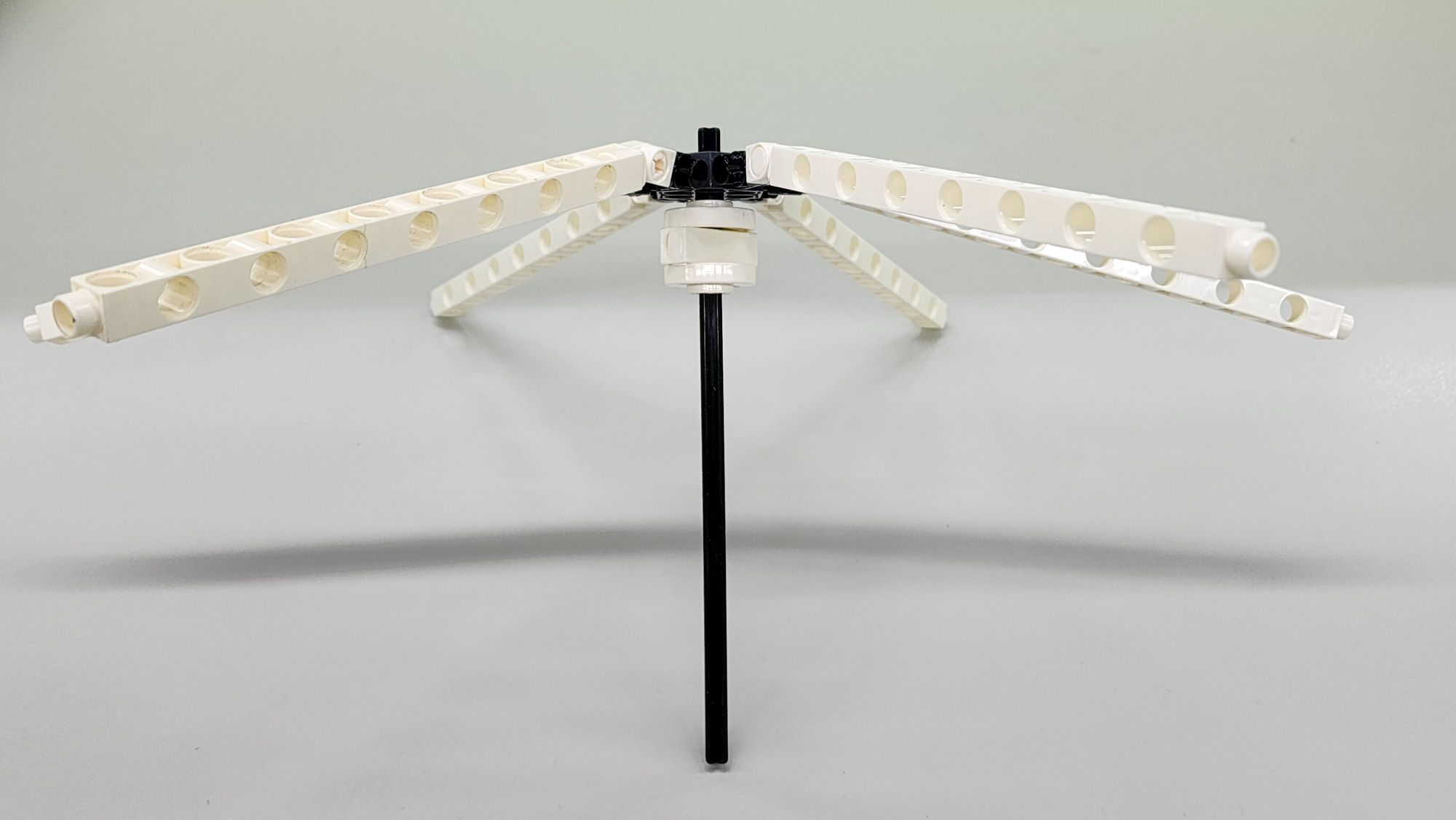
Next, we need to combine the umbrella ribs with the upper Notch. Install the C-1 HOLE CONNECTOR on the six pegs of the C-6-PIN HUB CONNECTOR (Figure 5).
Step 3: We make the umbrella's Shaft. We need to use the C-ROD CONNECTOR, C-3 HOLE ROD, and C-150mm AXLE Ⅰ(Figure 6). Assemble the parts to create the part B, completing the Shaft (Figure 7).
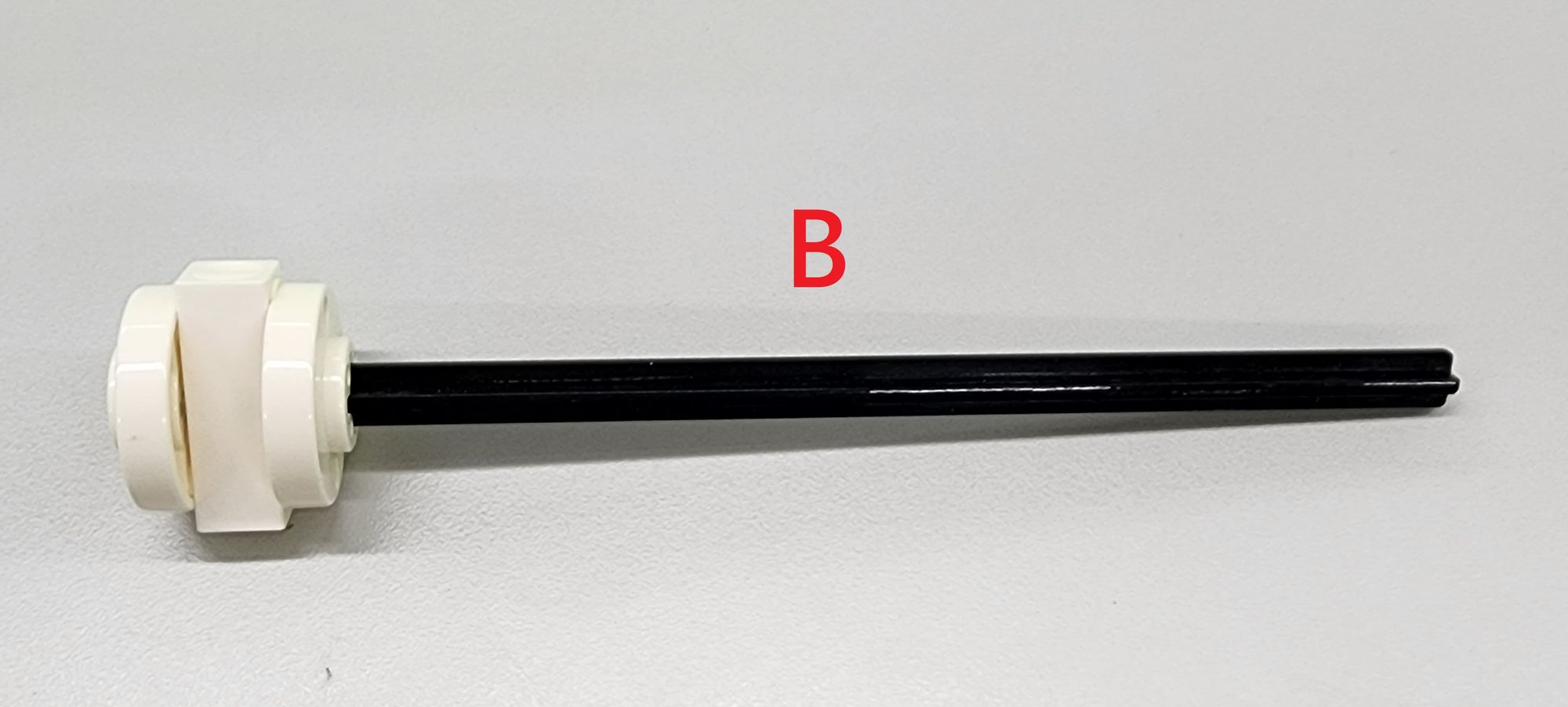
Next, we need to combine the Shaft with the Notch. Install the C-ROD CONNECTOR on the C-30mm AXLE Ⅱ (Figure 8). During installation, you can choose a C-ROD CONNECTOR and C-30mm AXLE Ⅱ combination that fits tightly. If the friction between the two parts is not sufficient, it may cause the umbrella to disassemble when opened.
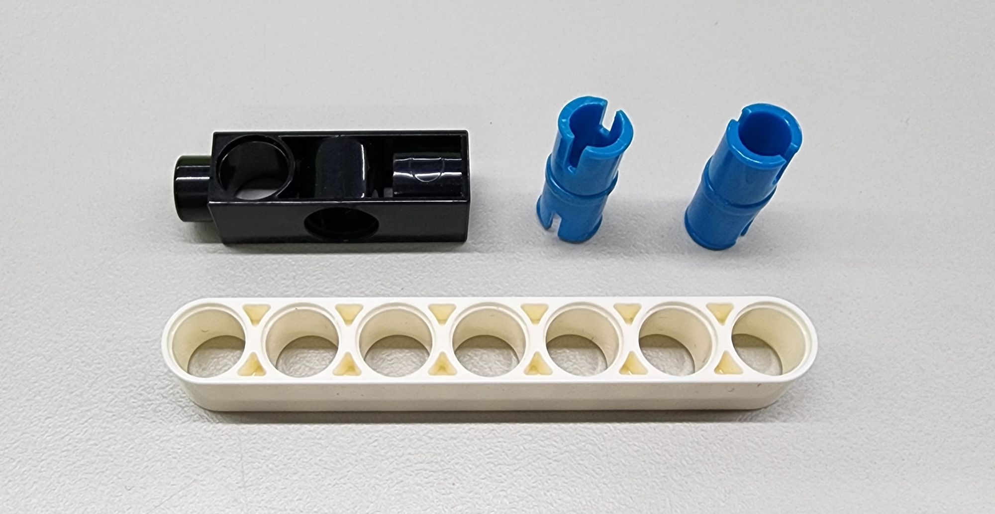
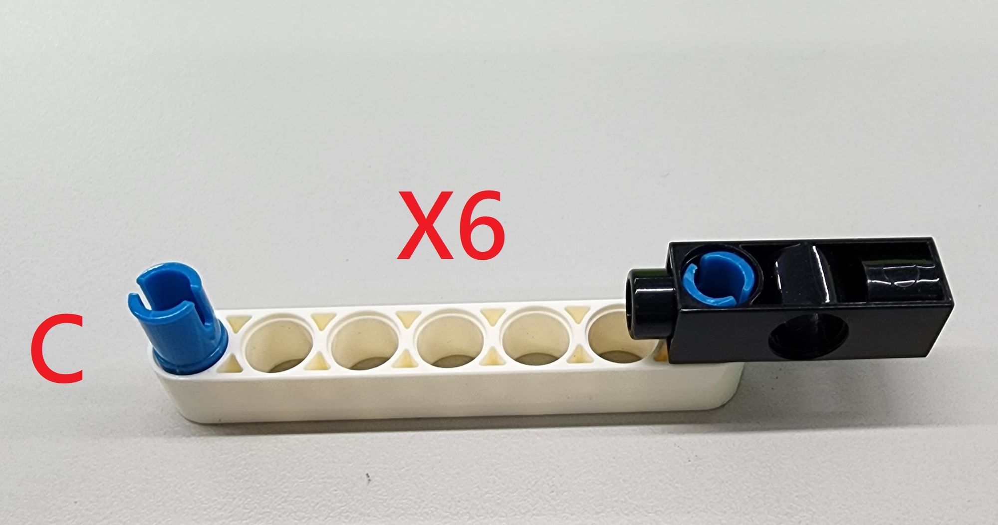
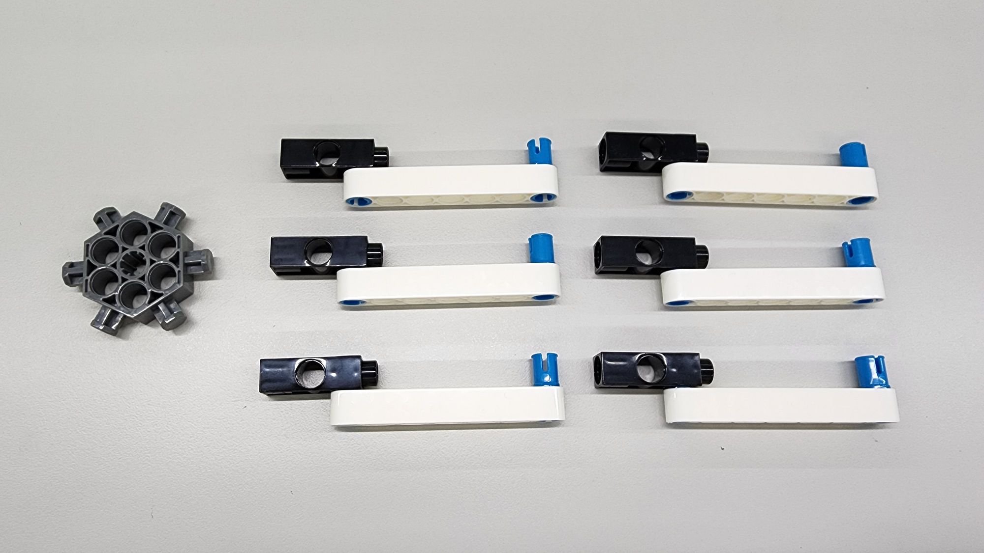
Step 4: We make the connecting rod connecting the Rib and the Runner. You will use a C-3 HOLE DUAL ROD, a C-AXLE CONNECTOR and a C-7 HOLE ROUND ROD (Figure 9). Assemble the parts into the part C according to the figure below. Since the part C needs to be connected to the Ribs, we then need to make six sets of them (Figure 10).
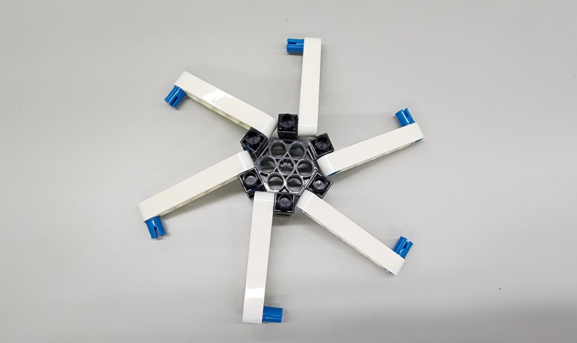
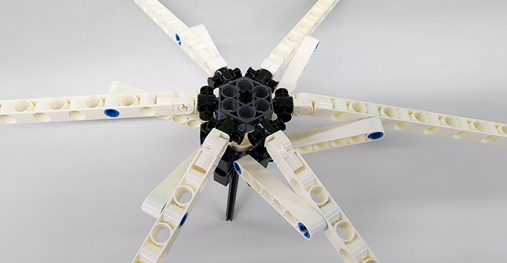
Step 5: We then combine the Runner of the umbrella with the part C. You need to prepare a C-6-PIN HUB CONNECTOR as the Runner (Figure 11). Install the six C-3 HOLE DUAL ROD of the part C on the C-6-PIN HUB CONNECTOR, make sure that the direction of each part C is the same (Figure 12).
Step 6: We insert the C-6-PIN HUB CONNECTOR (Runner) into the C-150mm AXLE Ⅰ (Shaft) (Figure 13). During installation, you need to confirm whether the directions of the two C-6-PIN HUB CONNECTOR are aligned. If they are not aligned, , you need to pull out the C-6-PIN HUB CONNECTOR (Runner) below and reinsert it after adjusting the direction.
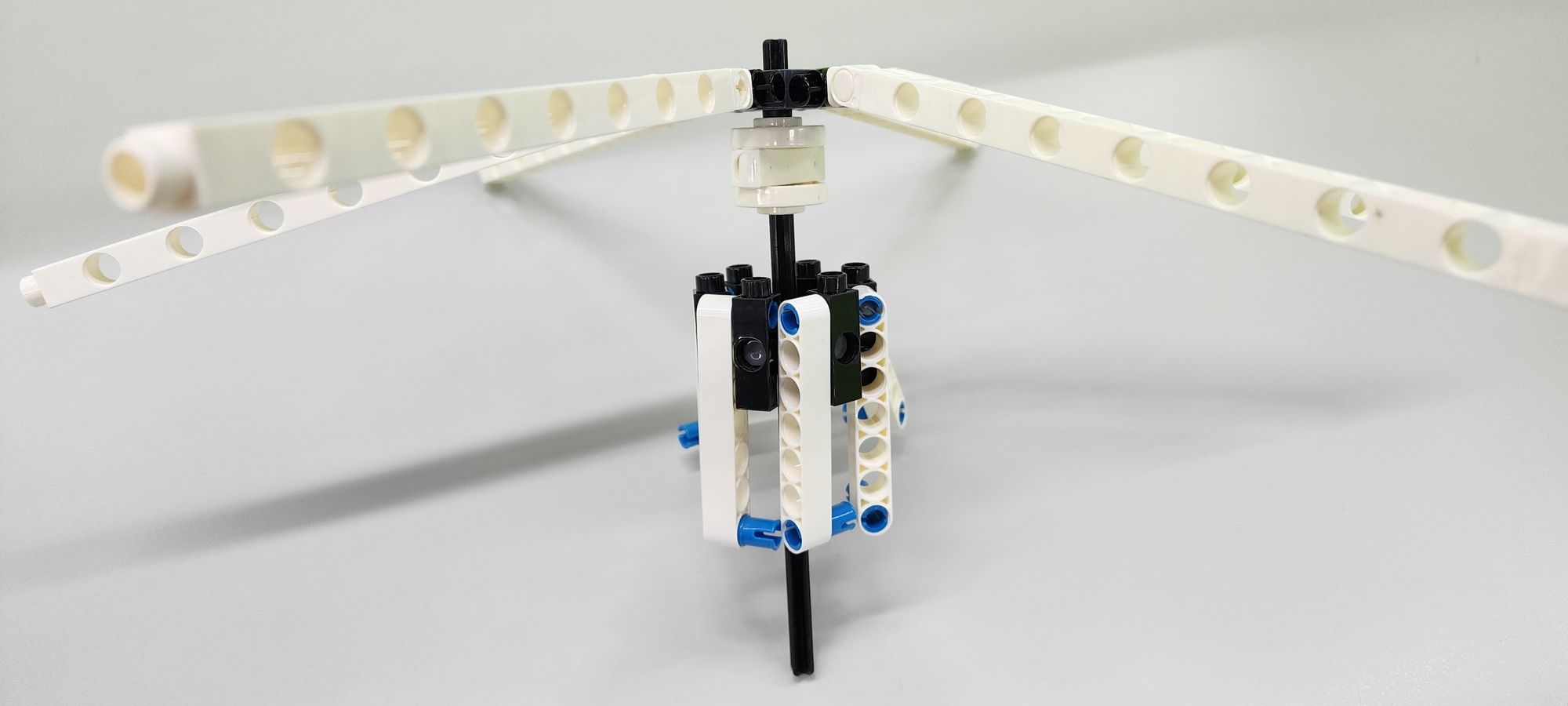
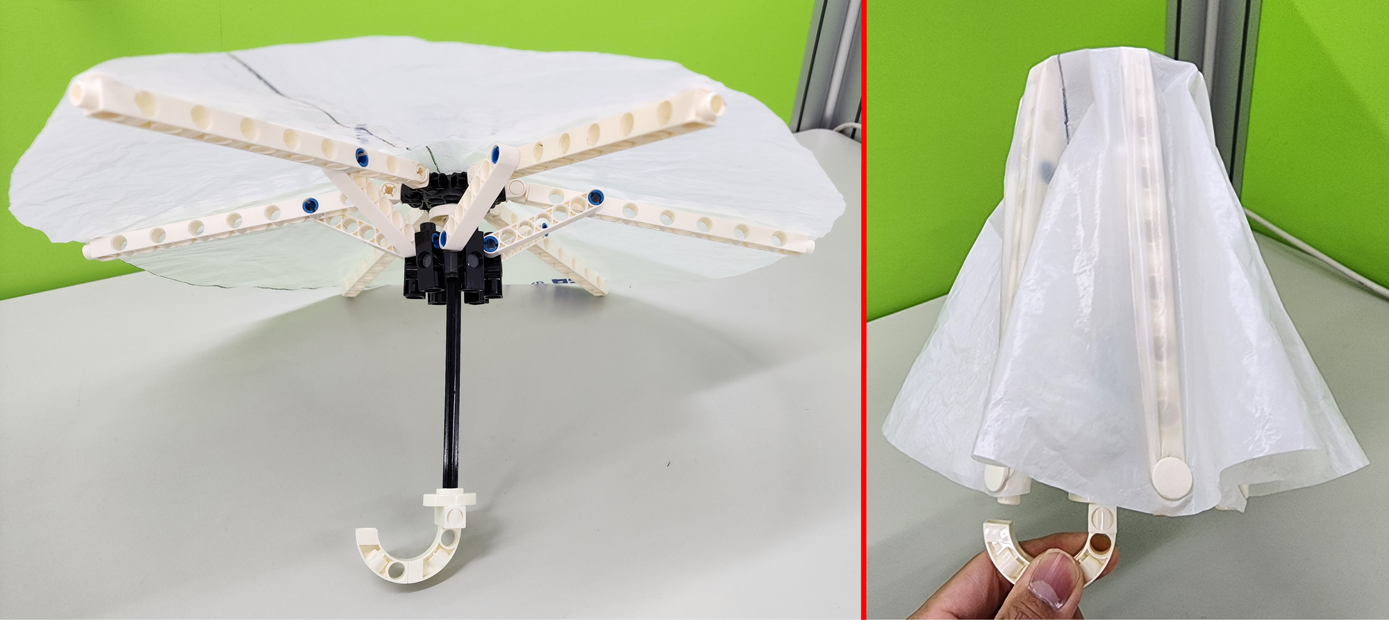
Then combine the C-AXLE CONNECTOR of the part C with the Rib, and the umbrella's mechanical linkage system is completed (Figure 14).
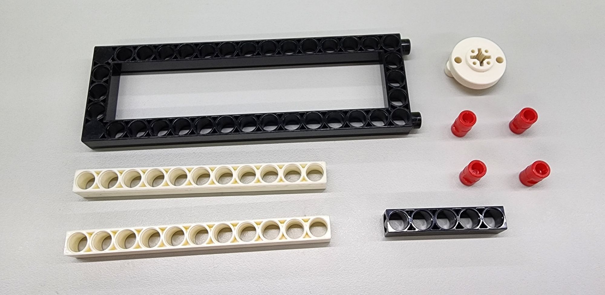
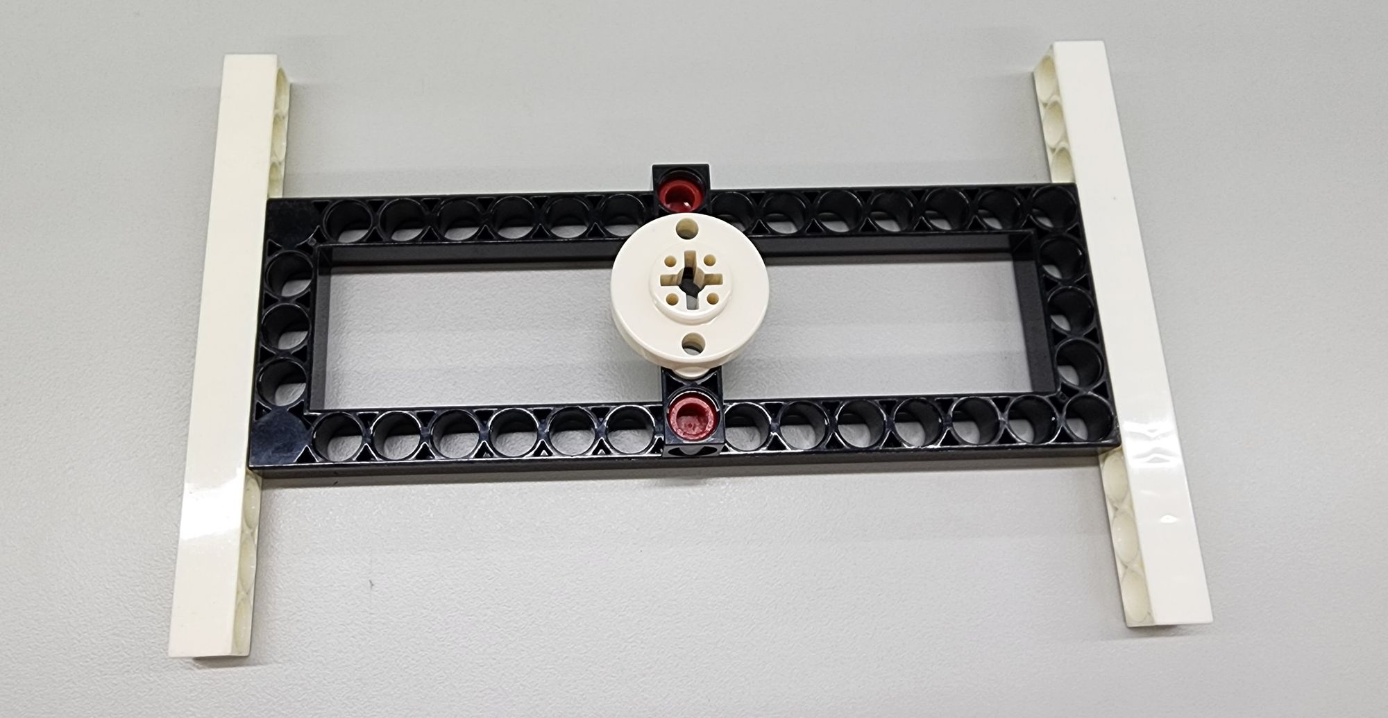
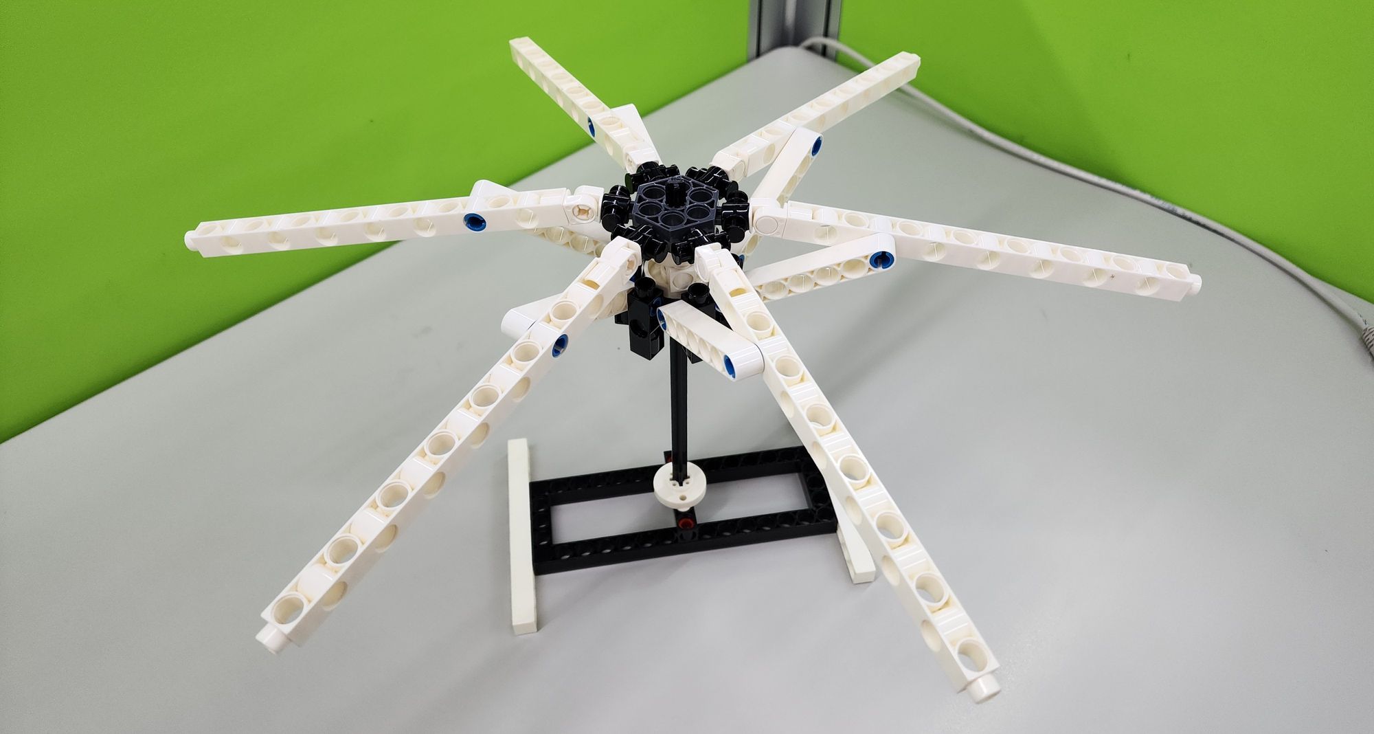
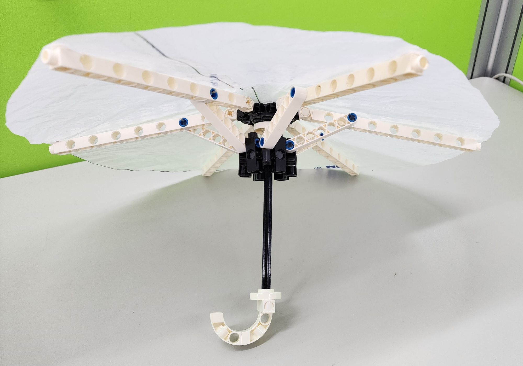
Step 7: We make a simple tripod to allow the umbrella to stand up for subsequent installation of the umbrella cloth. It mainly uses a C-5X15 FRAME, a C-11 HOLE ROD, a C-5 HOLE ROD, a C-LONG PEG and a C-ROD CONNECTOR. (Figure 15), assemble them as shown (Figure 16), and combine them with the C-150mm AXLE Ⅰ (Shaft) (Figure 17).
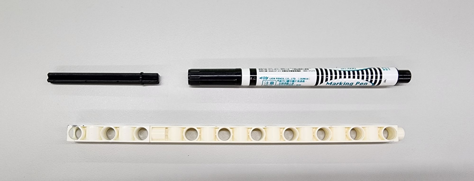
Step 8: We need to draw a circle, so we need to prepare a C-15 HOLE DUAL ROD, a C-5 HOLE DUAL ROD BOTTOM CLOSED at the bottom (7413-W10-W1W), a C-70mm AXLE Ⅱ and a Sharpie marker to use as a simple compass (Figure 18 ).
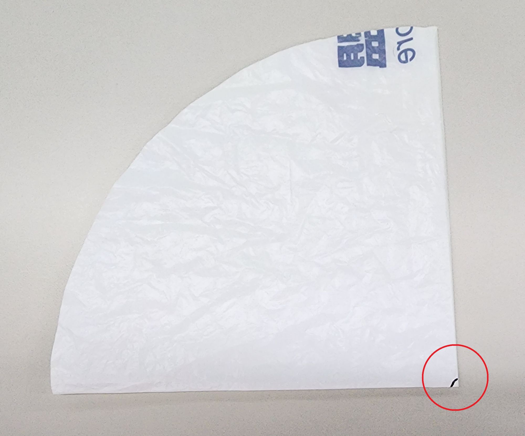
Step 9: We make the Cloth for the umbrella. It is recommended to use plastic bags or garbage bags with higher thickness and strength to increase the durability of the umbrella cloth. Teacher Raccoon used a plastic bag. He folded the plastic bag twice and flattened it. Then he placed the compass he had just made. He pressed the C-70mm AXLE Ⅱ with one hand and drew on the plastic bag with a Sharpie marker with the other hand. Draw 1/4 of the circle to complete a circular umbrella cloth with a radius of 20cm (Video 1).
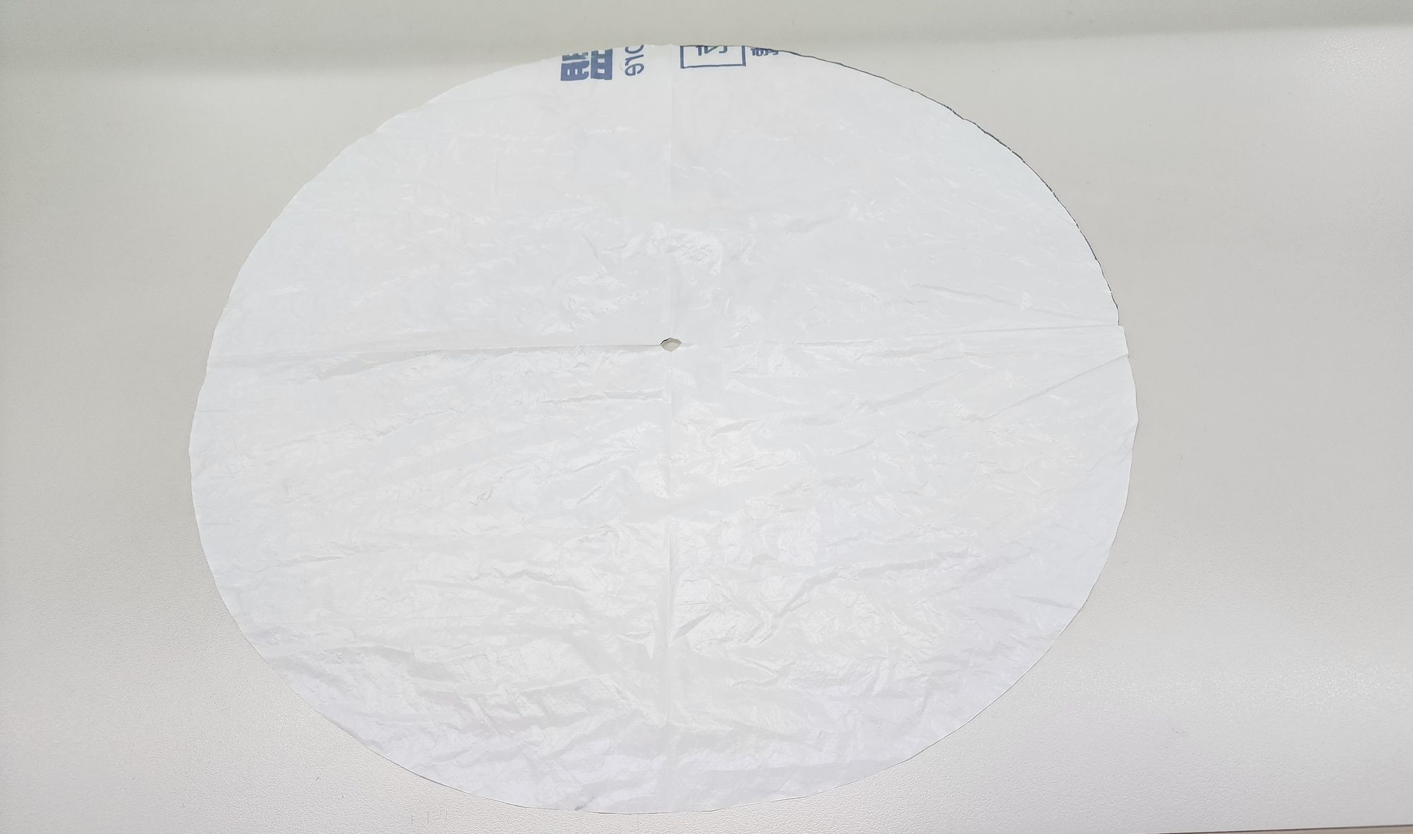
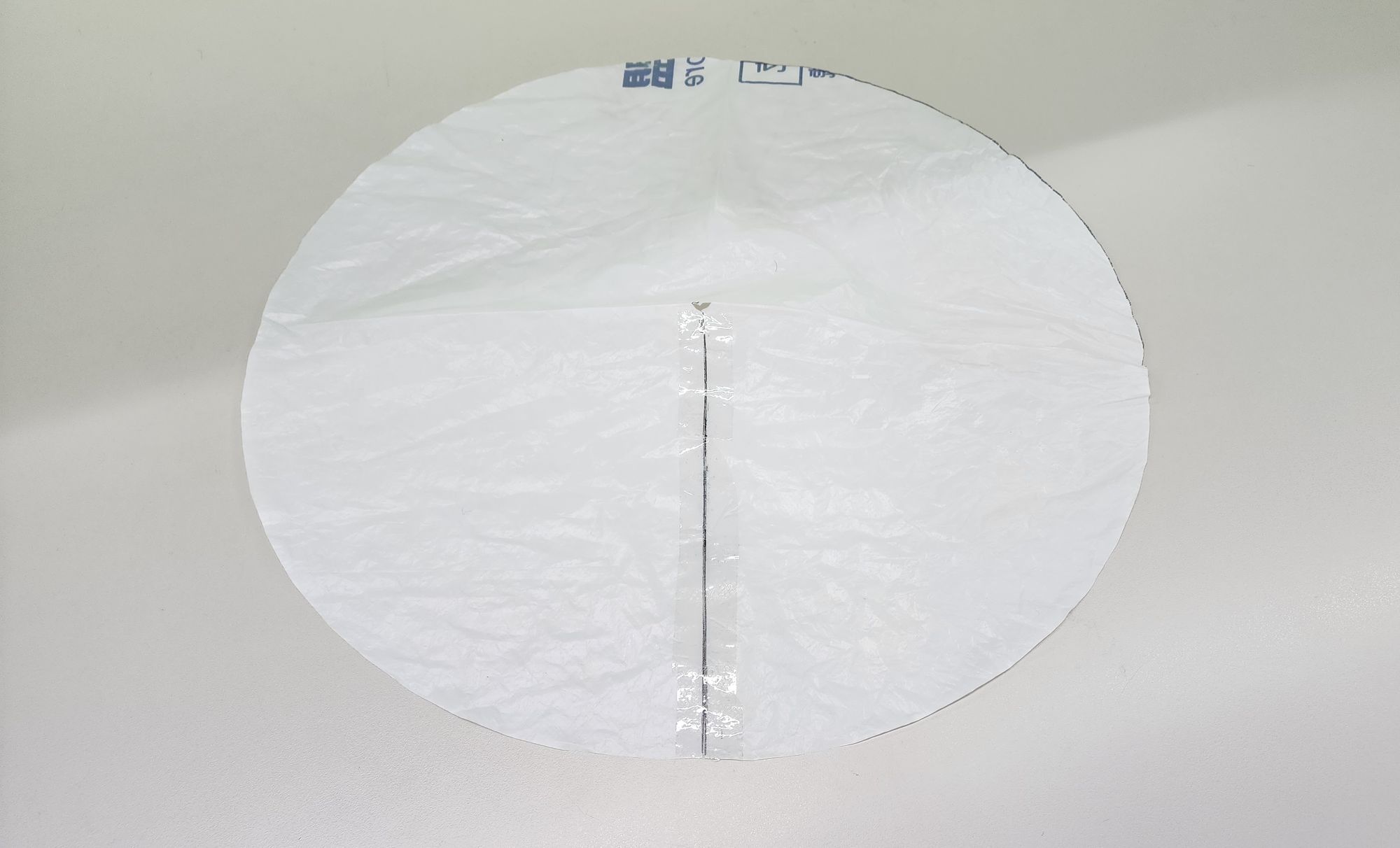
Next, we need to make a hole in the middle of the Cloth. Before spreading out the first 1/4 circle of umbrella cloth, we can cut the Cloth along the black line as shown (Figure 19). After completion, we will have a round umbrella cloth with hole in the middle (Figure 20).
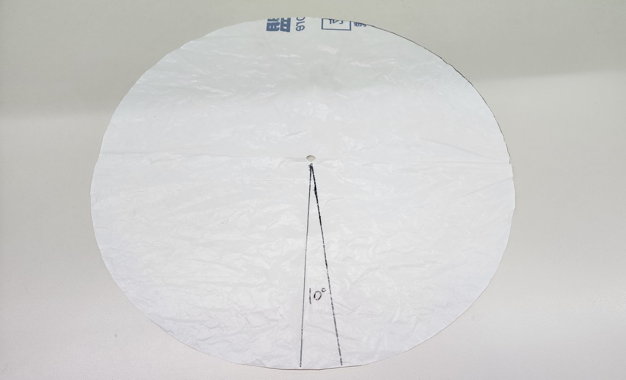
When the umbrella ribs are fully opened, they will maintain a slightly downward tilt angle to ensure that rainwater flows down from the umbrella surface. In order to make the umbrella surface fit better with the downwardly tilted Ribs, we need to modify the round umbrella cloth into the Conical type. First, use a protractor to draw a section of about 5 to 10 degrees on the umbrella surface (Figure 21). Then cut this section and use tape to re-glue the Cloth. We will get a conical umbrella cloth ( Figure 22)!
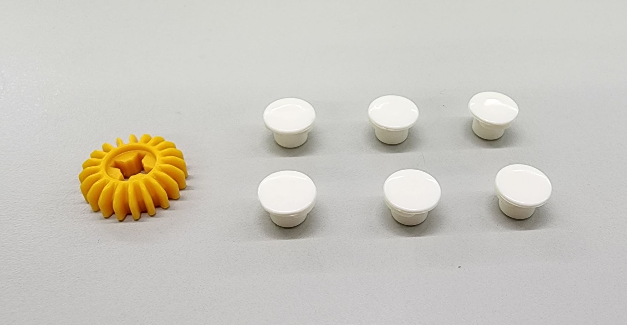
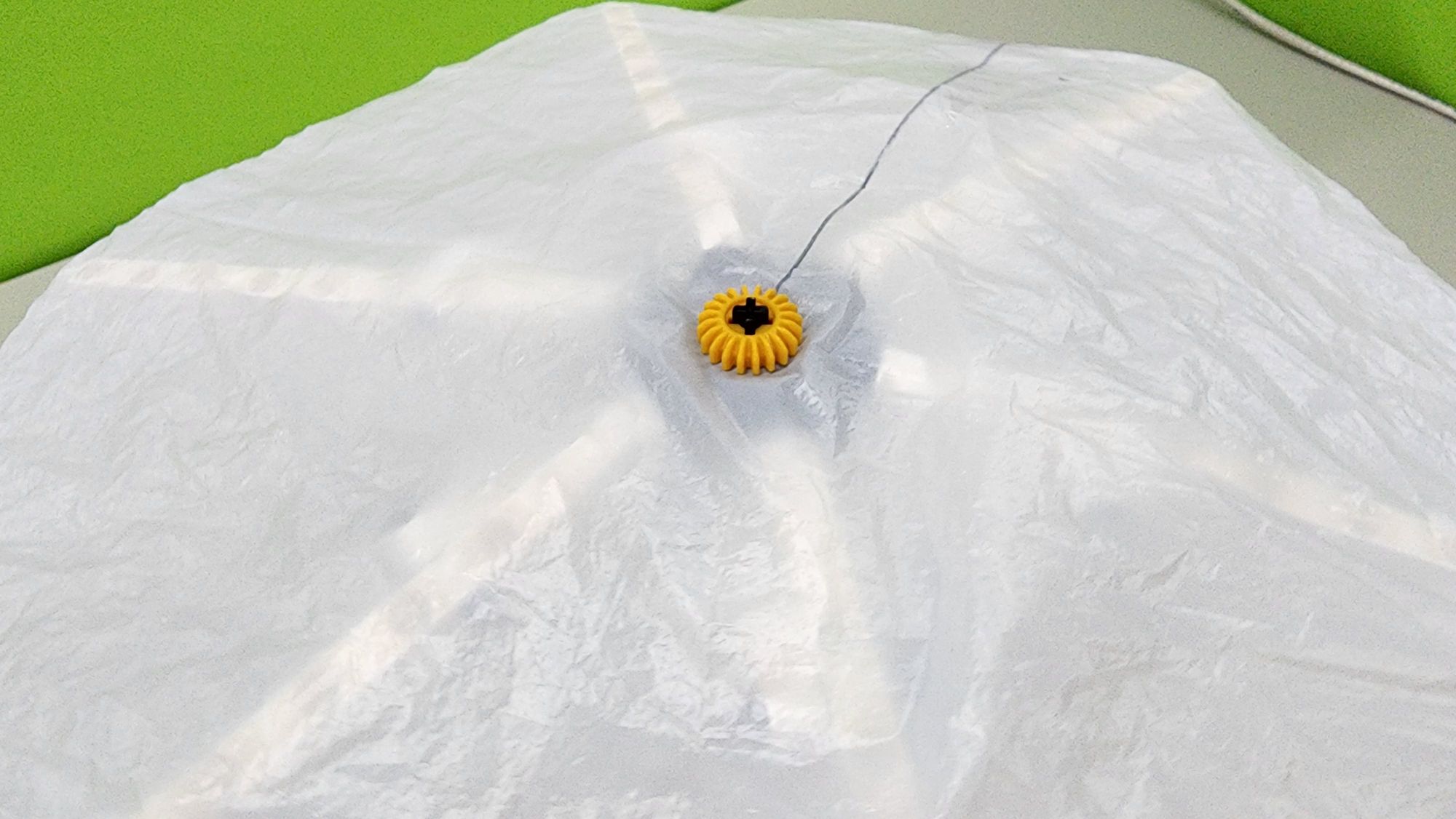
Step 10: We now need to fix the umbrella cloth. We use the C-20T GEAR and the C-SHORT BUTTON FIXER (Figure 23). First, pass the hole in the middle of the umbrella cloth through the Ferrule (C-30mm AXLE Ⅱ), and then insert the C-20T GEAR to fix it (Figure 24).
Then press the Cloth outward from the center point, align the outermost holes of the Rib (C-15 HOLE DUAL ROD), and then use scissors and other sharp objects to pierce the umbrella cloth (an adult must accompany or do the operation). When the hole in the umbrella cloth is about the same size as the C-SHORT BUTTON FIXER, you can press down the C-SHORT BUTTON FIXER to fix the Cloth (Video 2). Repeat this step until all six ribs are combined with the umbrella surface, and the Tips of the umbrella are completed (Figure 25).
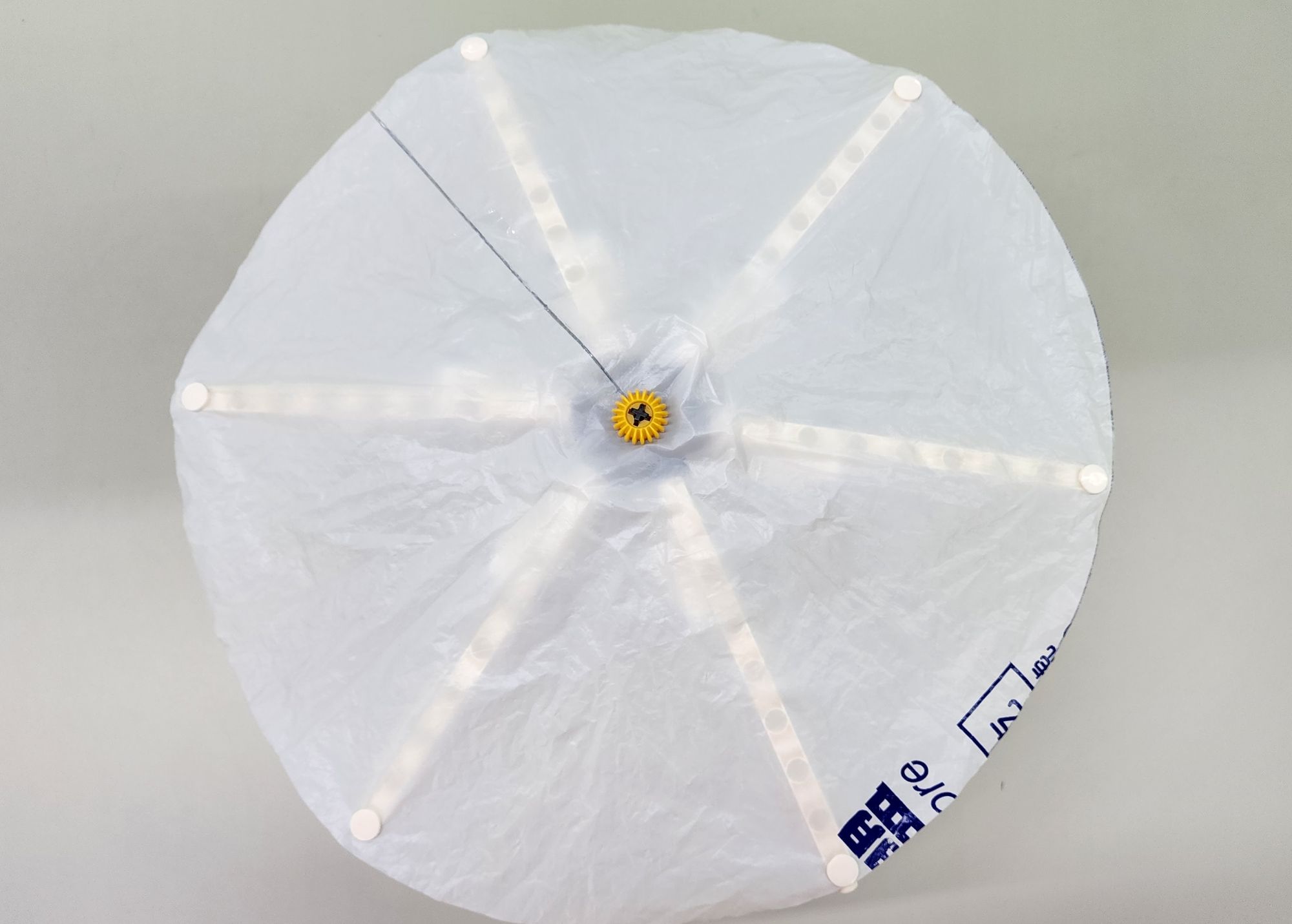
Now we can repeatedly close and open the umbrella to test the function of the umbrella ribs and whether the position of the umbrella surface is correct (Video 3).
Step 11: We now make the Handle of the umbrella. We use the C-BENDED ROD, C-3 HOLE DUAL ROD and C-ROD CONNECTOR (Figure 26). Combine them as shown to form the part D (Figure 27).
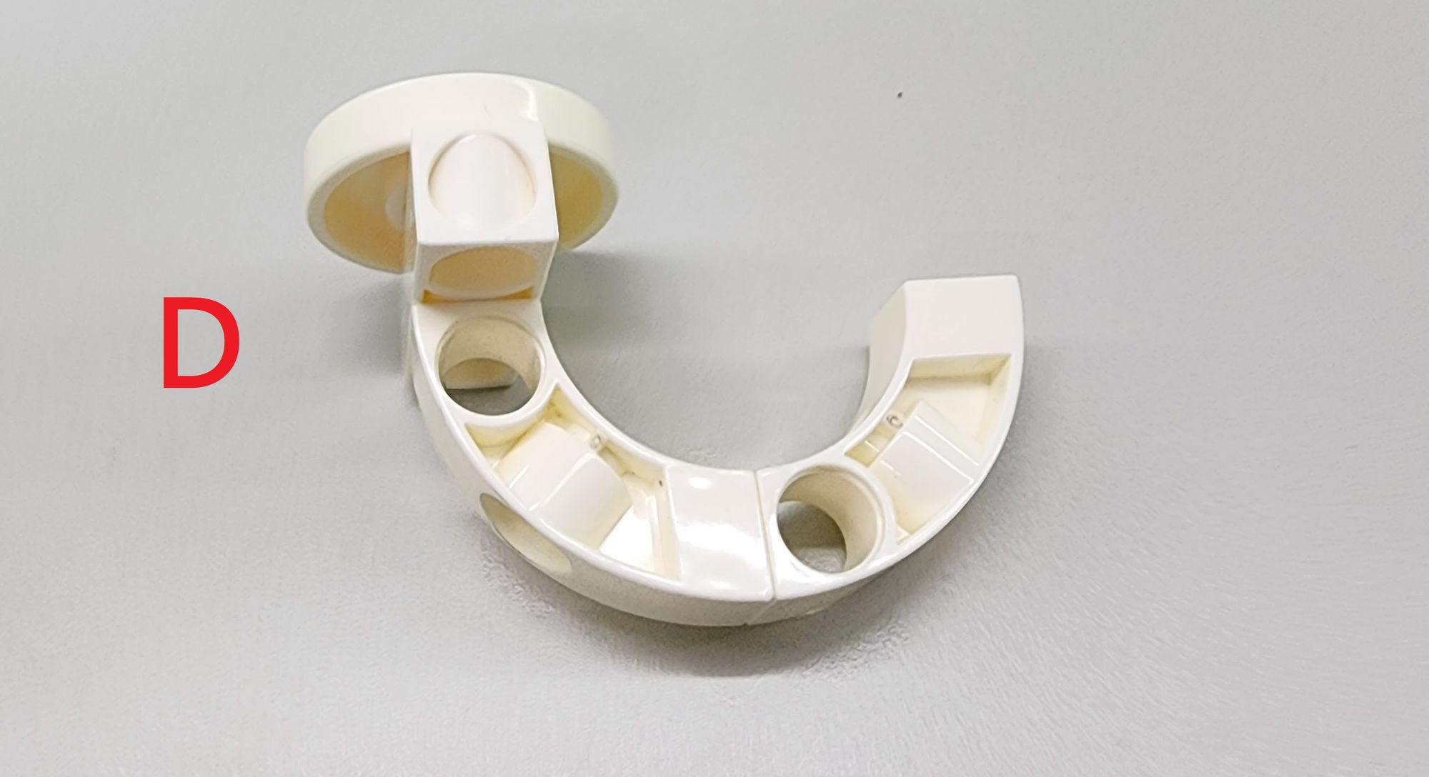
Finally, we can remove the tripod made in the seventh step and replace that with the part D (Handle). Here, we need the C-ROD CONNECTOR and a C-30mm AXLE Ⅱ to make it combine tightly so that it can prevent disassembly. In this way, the umbrella model is completed (Figure 28). Now let’s test it and see how it works ٩(๑>∀<๑)۶(Video 4)!
◆Conclusion
The umbrella model created this time is not only identical in appearance and structure to a real umbrella but can also be used as a real umbrella. Try simulating rain by using water from a faucet. Open the umbrella and place it under the faucet to test if it can resist the water. In addition, you can paint on the umbrella fabric or replace it with fabrics featuring different patterns, creating a unique umbrella!
Today's sharing ends here. If you enjoyed this article, remember to share it generously. See you next time, bye-bye!
◆Scientific principles
The umbrella utilizes a linkage mechanism, where the linkage is primarily composed of a force arm and movable pivot. The most common type is the telescopic scissor-type linkage (Video 5). The linkage mechanism in the umbrella is mainly used to connect the Runner (C-6-PIN HUB CONNECTOR) and the umbrella ribs (C-15 HOLE DUAL ROD). When we need to close the umbrella, pulling down the Runner generates a downward force that, in turn, pulls down the Ribs, and vice versa (Video 6). Try experimenting to see if changing the connection position of the linkage will affect its operation.
◆Curriculum(NGSS):
2-PS1-2. Analyze data obtained from testing different materials to determine which materials have the properties that are best suited for an intended purpose.
3-PS2-1. Plan and conduct an investigation to provide evidence of the effects of balanced and unbalanced forces on the motion of an object.
3-5-ETS1-3. Plan and carry out fair tests in which variables are controlled and failure points are considered to identify aspects of a model or prototype that can be improved.
#Gigo#Gigo Lab#Learning Lab#Fun Lab
◆Reference:
 Contributors to Wikimedia projects
 Contributors to Wikimedia projects
 Contributors to Wikimedia projects
.jpg)
Please sign in to vote.