Science in daily life: EP8 – Hand-operated Jack


Hello, everyone. I am Teacher Raccoon. I wonder if any of you have gone to an auto repair shop for car repairs? When cars or motorcycles need to have their bottom parts replaced, mechanics usually use a device called a jack to lift the vehicle.
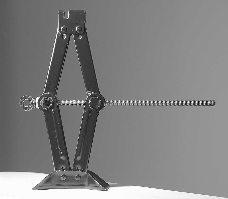
A jack is a device capable of lifting heavy objects and can be categorized into many types based on different principles or structures, such as the common hydraulic jack found in repair shops, or the screw-type jack that can be stored in a vehicle. Today, Teacher Raccoon will show you how to make a hand-operated jack based on the simple machine (screw) principle, also known as a telescopic screw jack. Let's dive into the steps of making a jack!
◆Assembly Steps
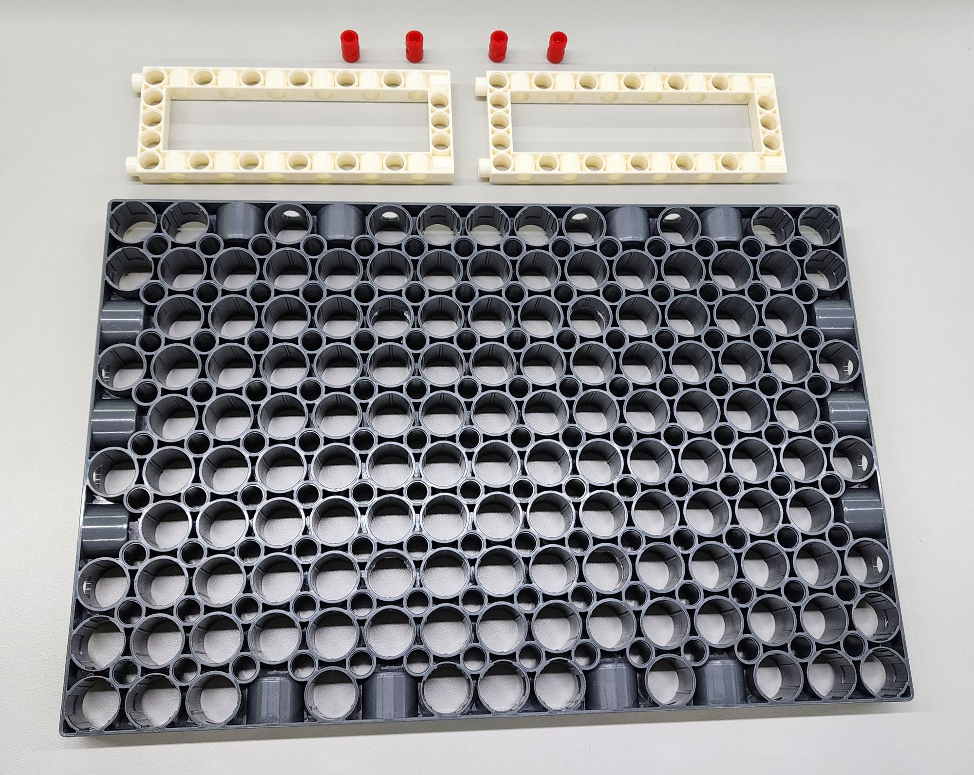
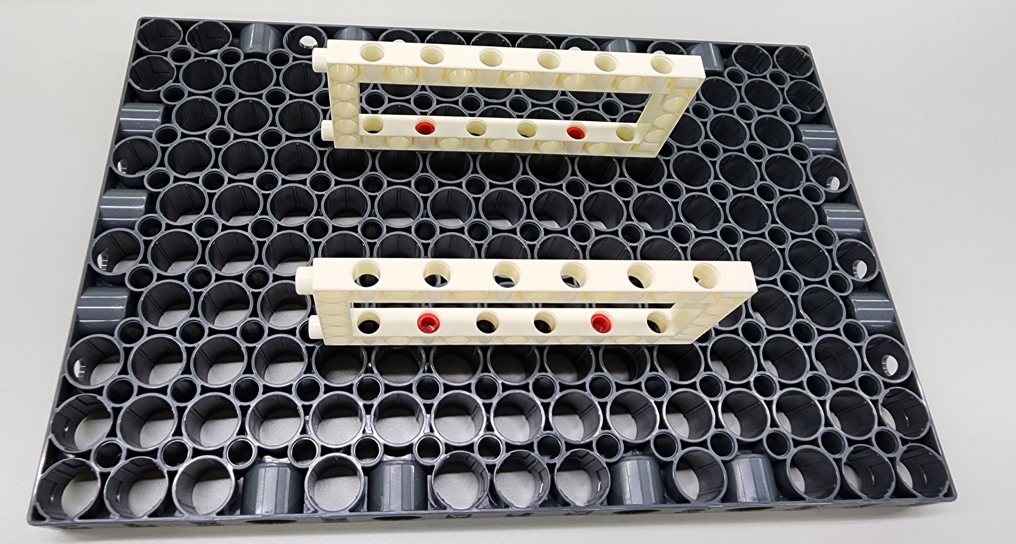
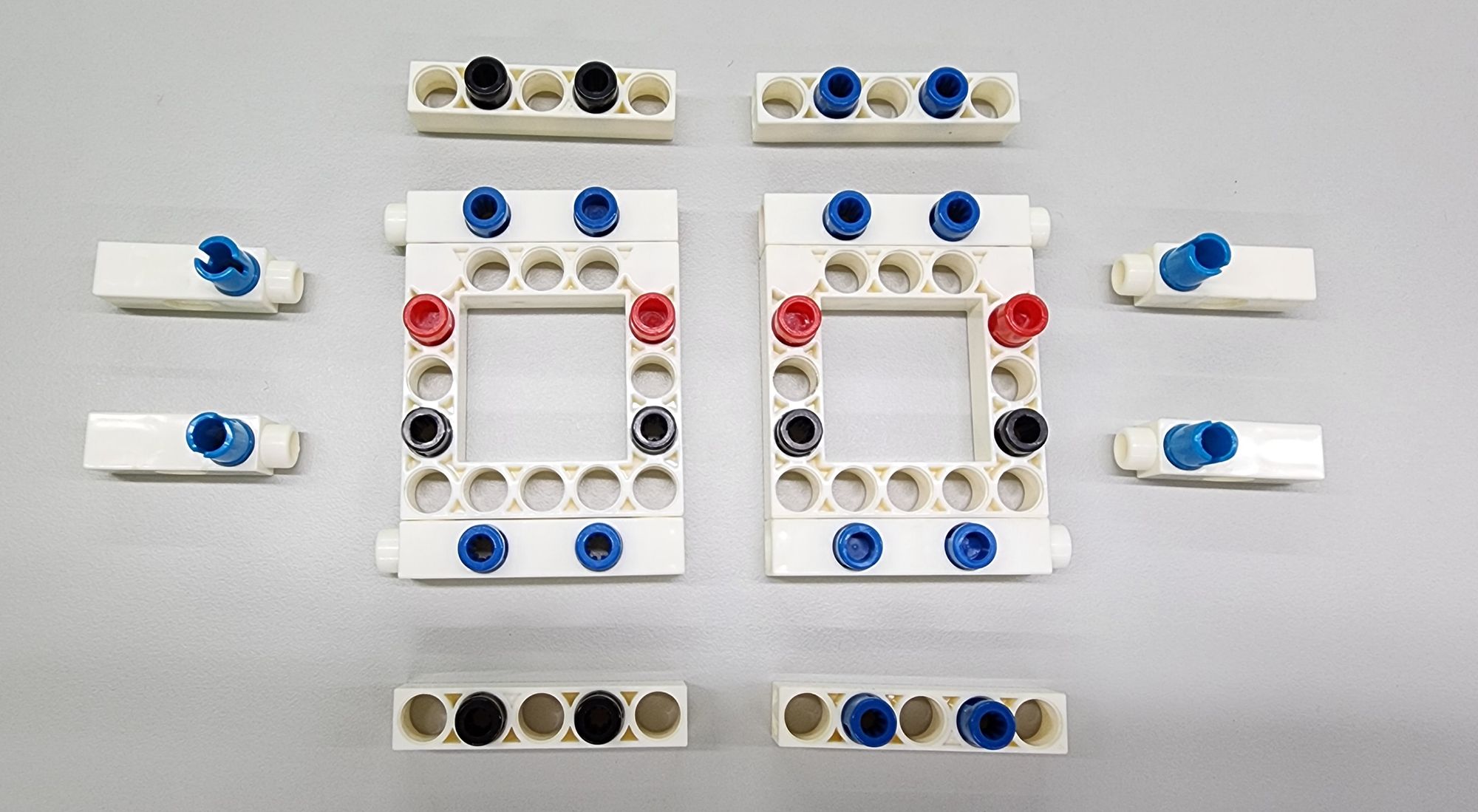
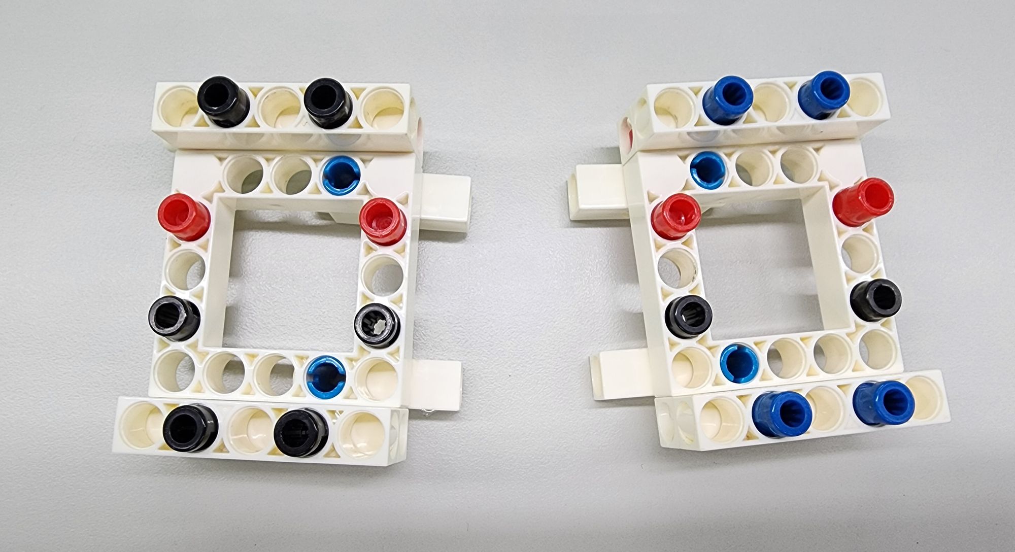
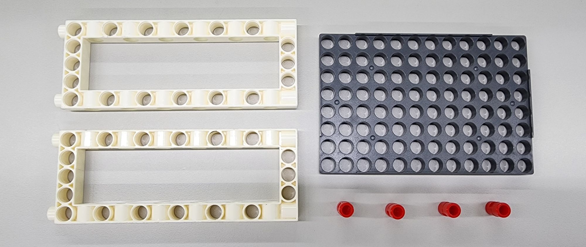
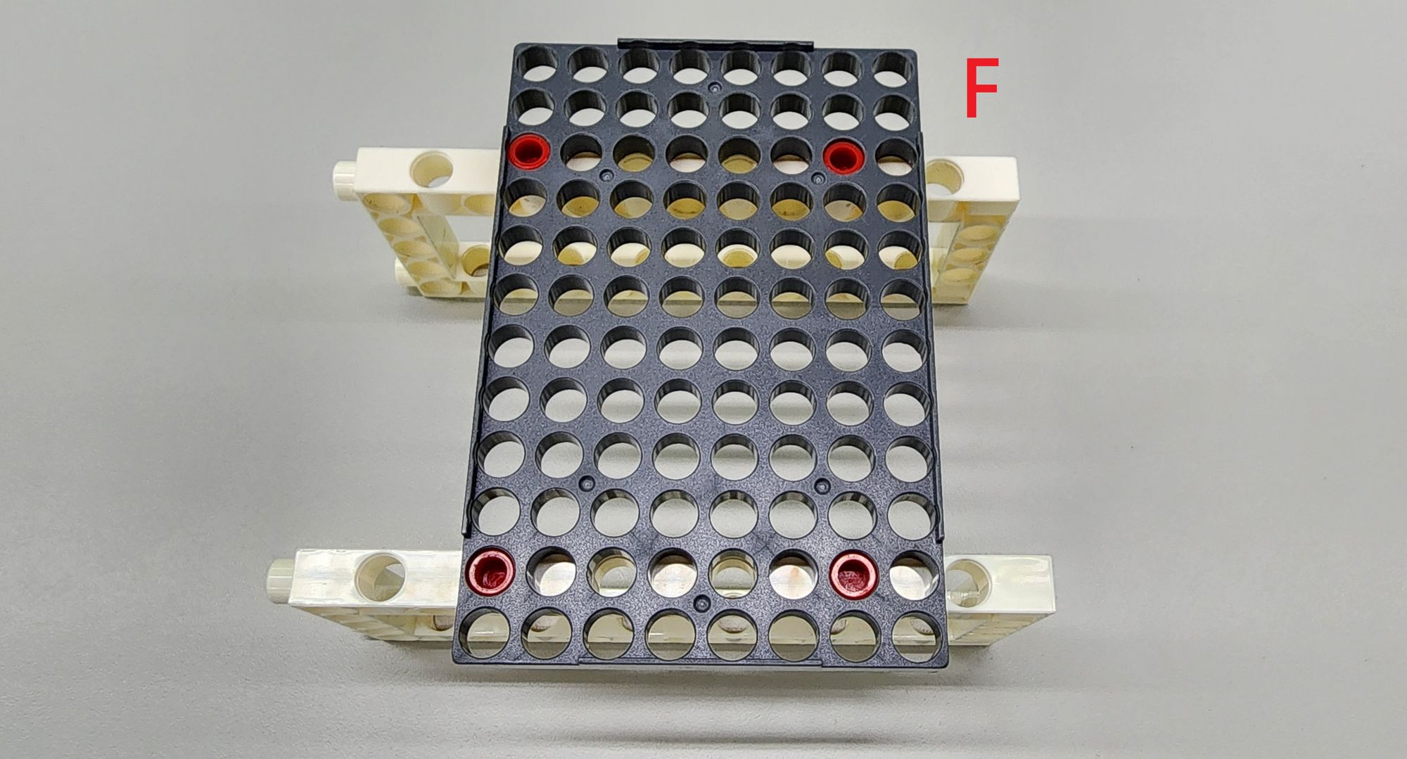
Step 1: we make the base of the jack. We need to use one C-JUMBO BASE GRID, two C-5x13 DUAL FRAME and some C-LONG PEG (Figure 1). Assemble the above parts on the C-JUMBO BASE GRID accordingly (Figure 2).
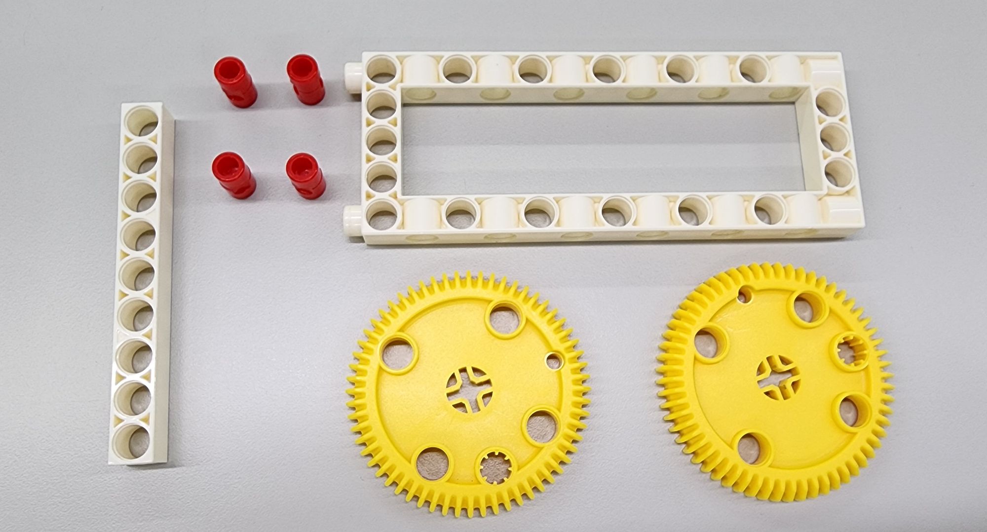
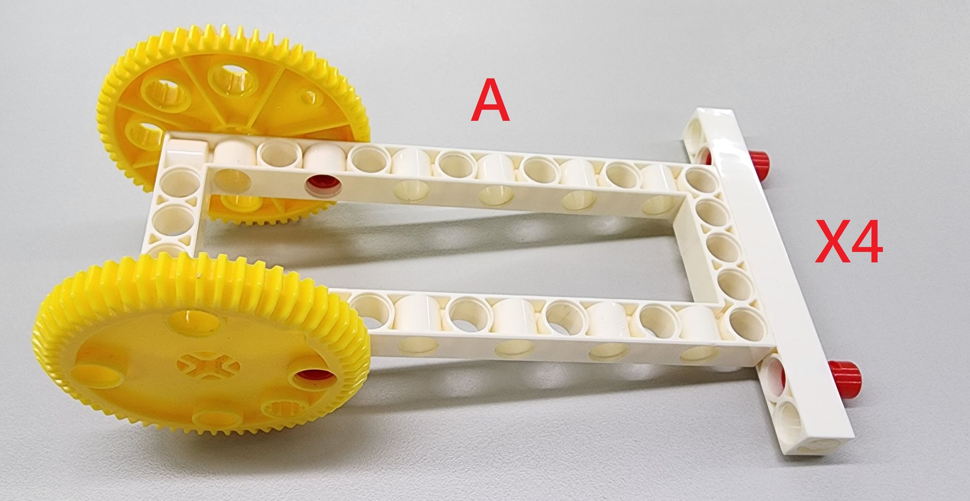
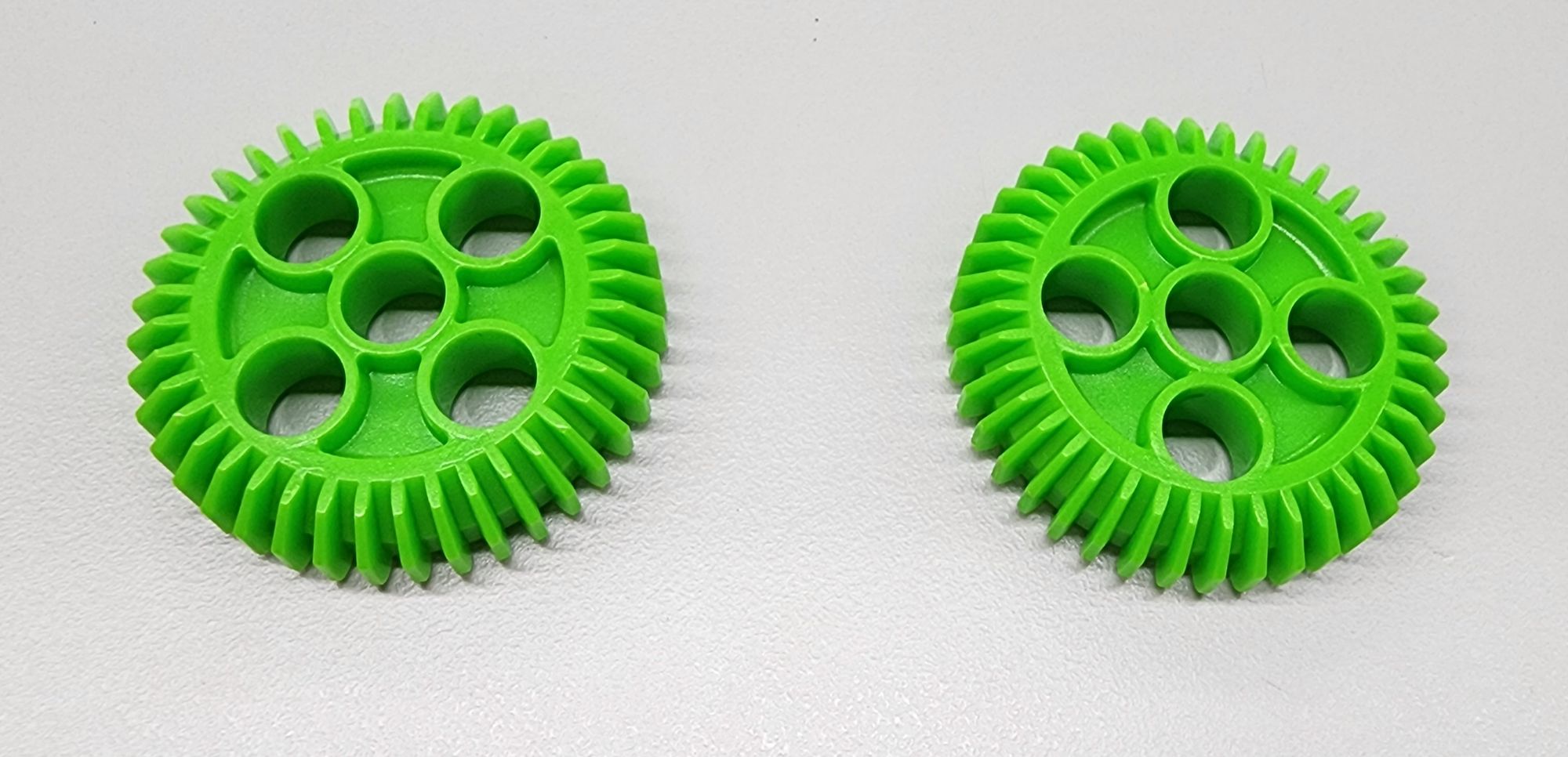
Step 2: we make the cantilever of the jack. It mainly uses C-LONG PEG, C-5x13 DUAL FRAME, C-9 HOLE ROD and C-60T GEAR (Figure 3). Assemble them into part A. The jack has four cantilevers, so a total of four parts A need to be made (Figure 4).
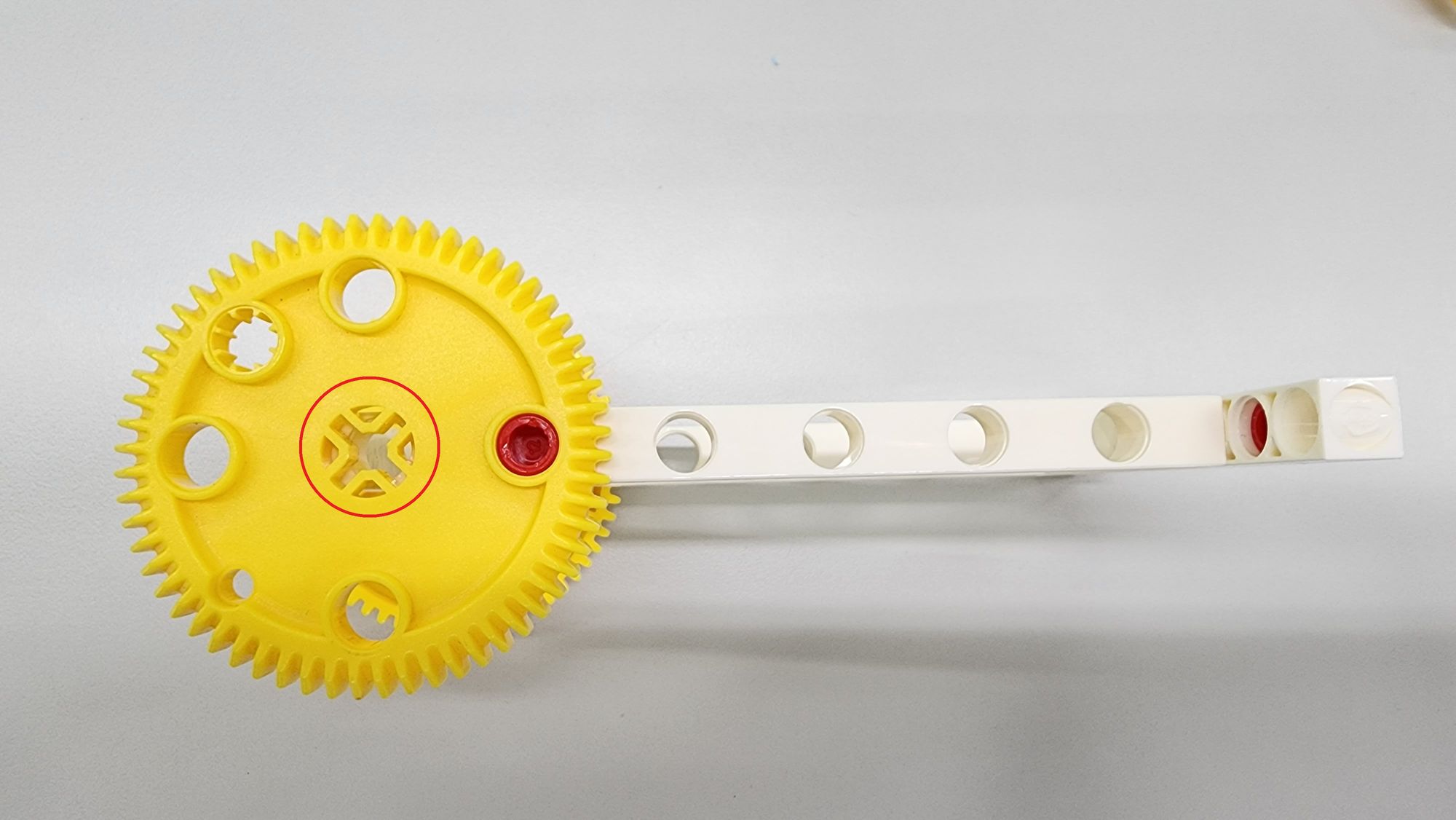
When assembling part A, you need to ensure that the cross hole in the middle of the C-60T GEAR is aligned with the hole in the C-5x13 DUAL FRAME (Figure 5).
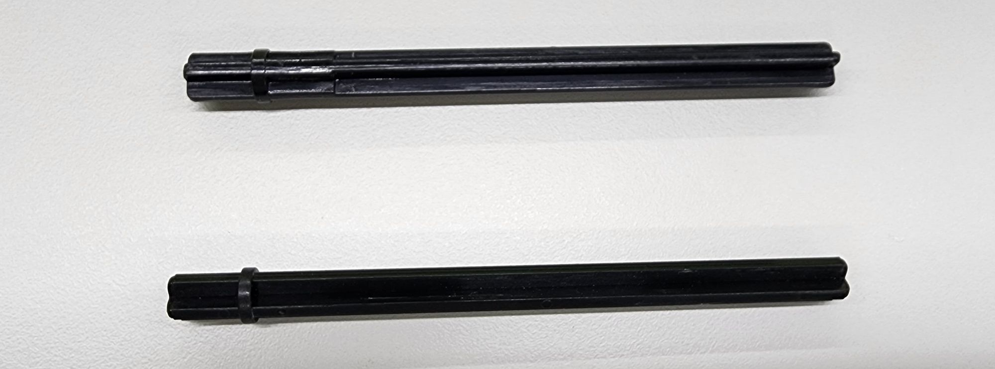
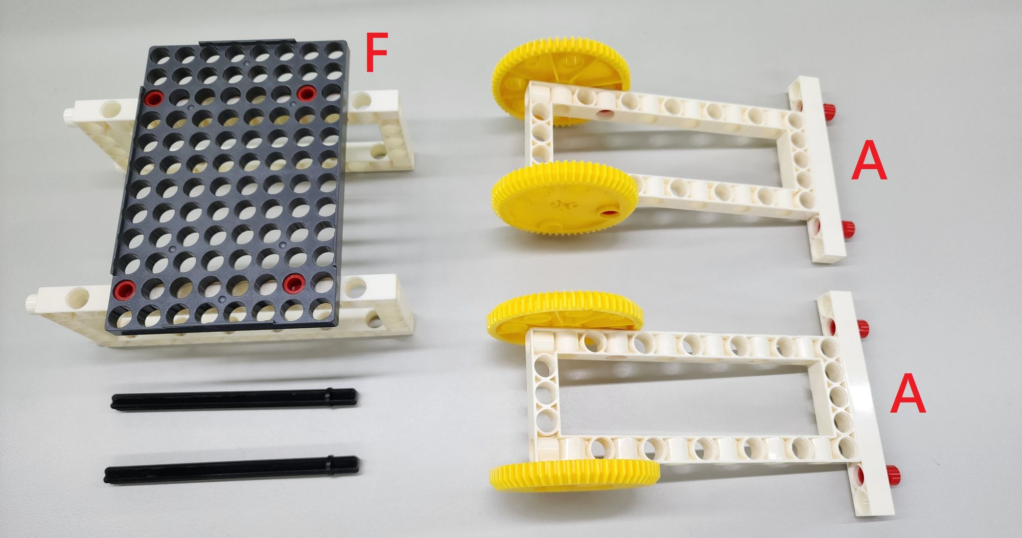
Then we can use two C-100mm AXLE (Figure 6) to combine the cantilever and the base. According to the diagram, pass the C-100mm AXLE through the C-5x13 DUAL FRAME on the base and the two parts A (Figure 7) to complete the following installation of the lower half cantilever. The other two parts A will be used in subsequent assembly steps, so we can set them aside for now.
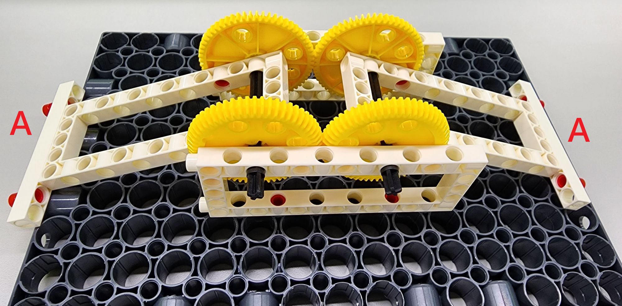
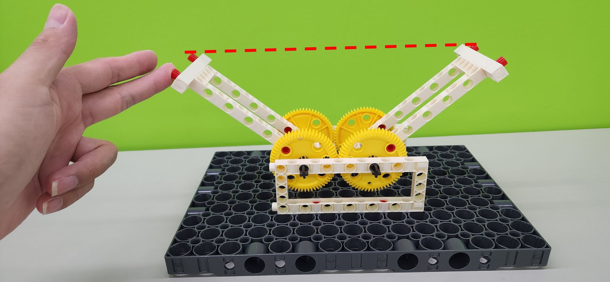
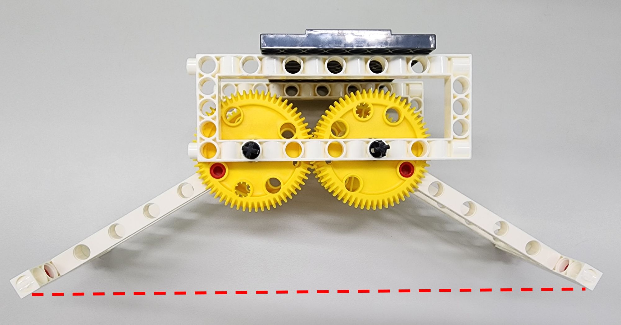
After completing the assembly, we need to check whether the cantilever operates normally. First, confirm that the C-60T GEAR of the two cantilevers (part A) are meshed with each other. Then when we lift one of the cantilevers, the other cantilever should also rise and the height of the two cantilevers must be the same (Figure 8).
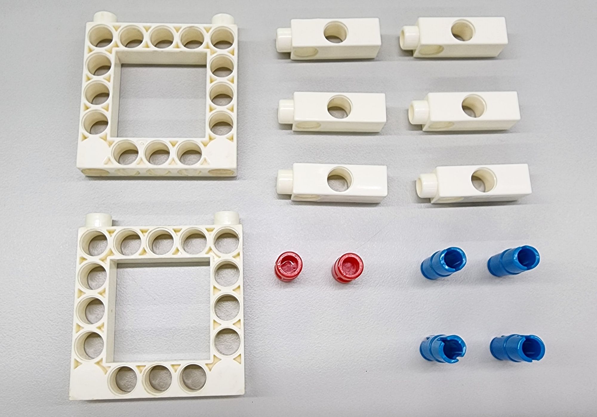
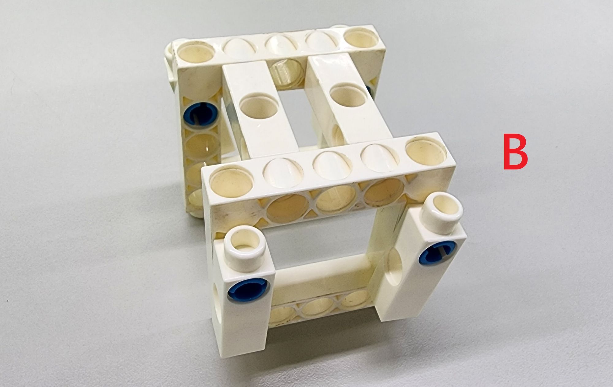
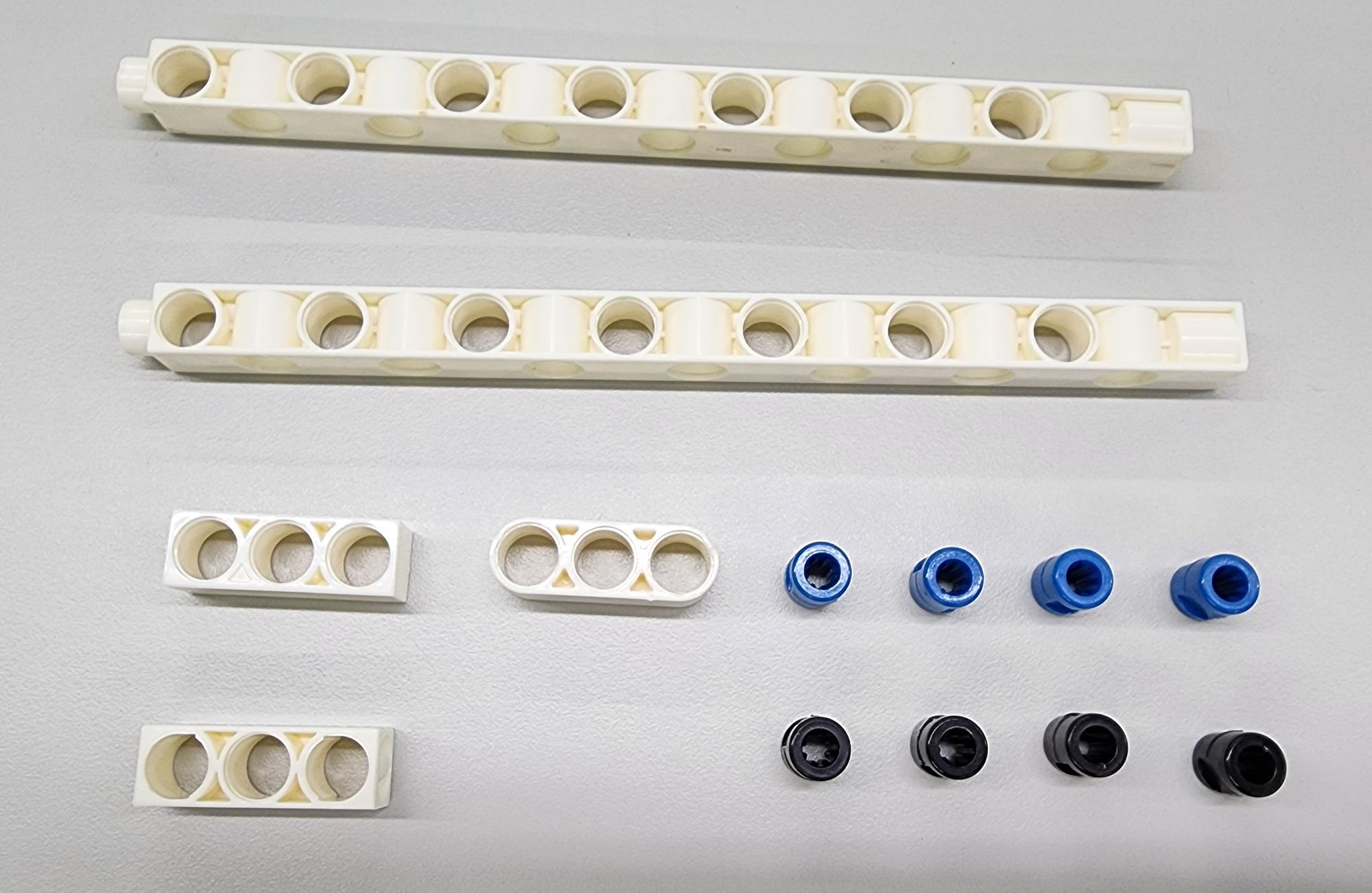
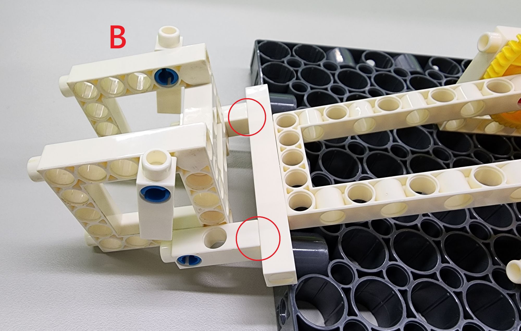
Step 3: we use two C-5X15 FRAME, six C-3 HOLE DUAL ROD, C-AXLE CONNECTOR, and C-LONG PEG (Figure 9). Assemble the parts into Part B (Figure 10) accordingly. The function of this part is a retainer which is used for fixing threaded rods and connecting cantilevers.
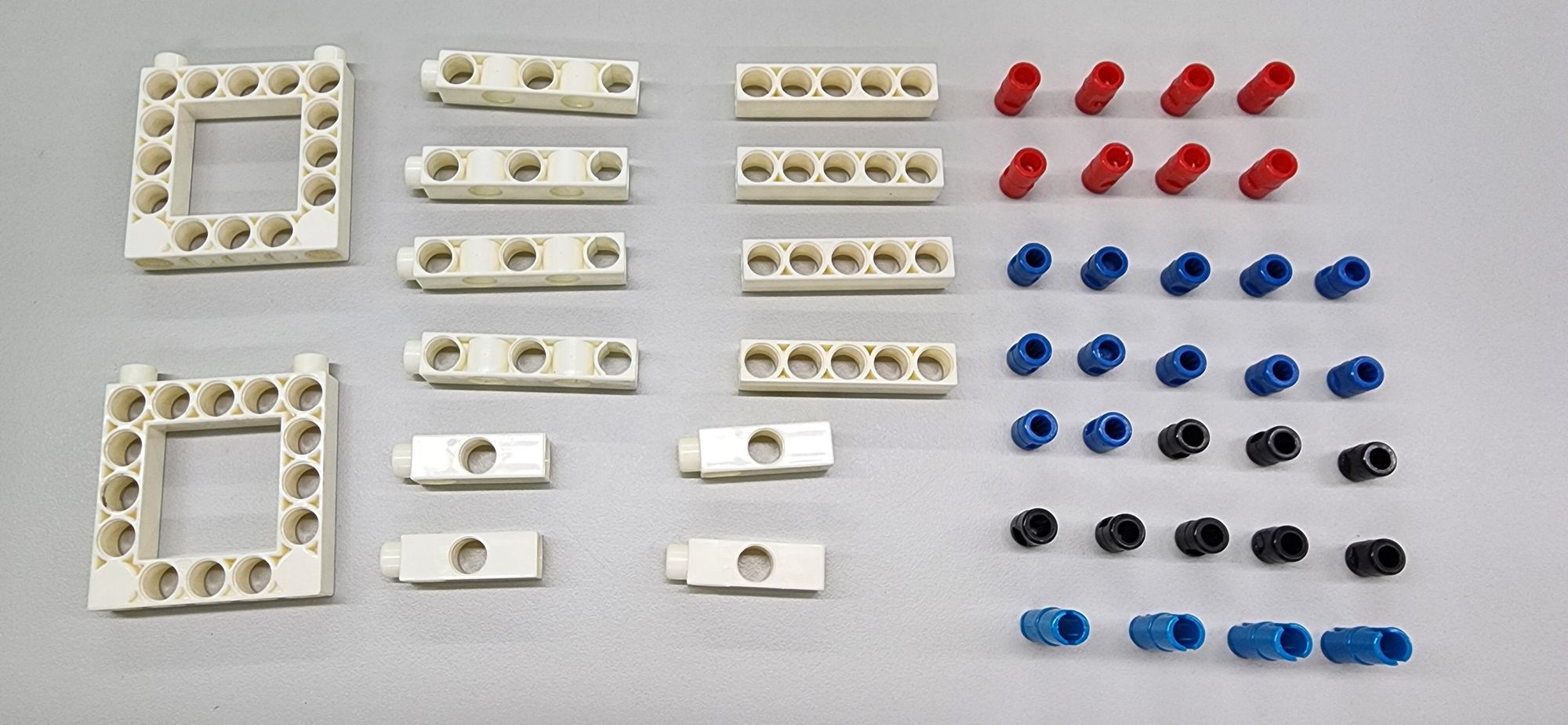
Step 4: we use the two C-5X15 FRAME, four C-3 HOLE DUAL ROD, four C-5 HOLE DUAL ROD BOTTOM CLOSED, C-5 HOLE ROD, C-LONG PEG, B-SHORT PEG, and C-AXLE CONNECTOR (Figure 11). Assemble the parts according to the figure below into two symmetrical parts (Figures 12 and 13).
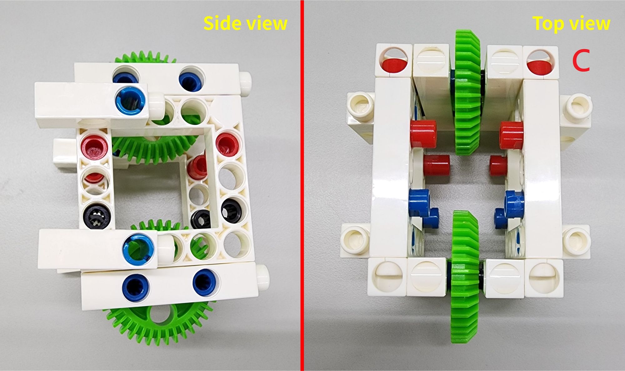
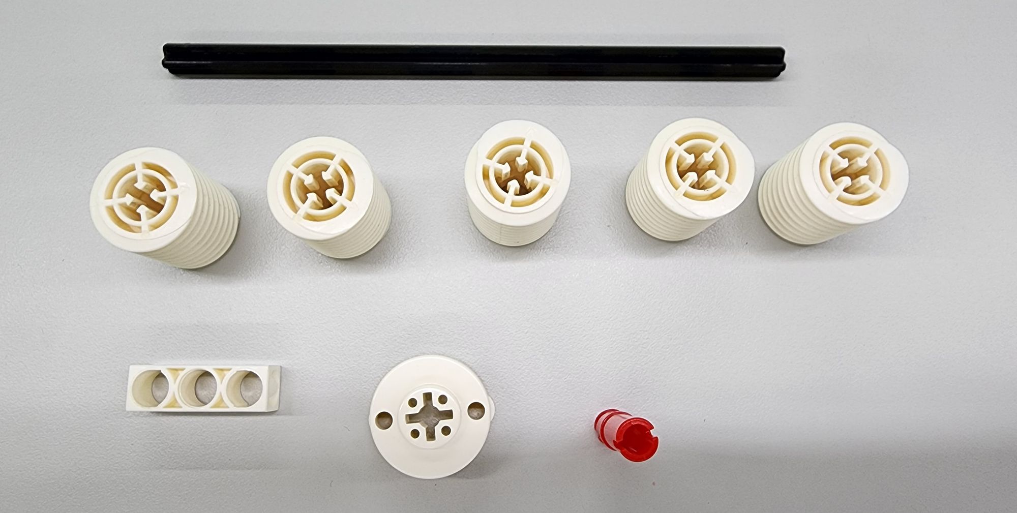
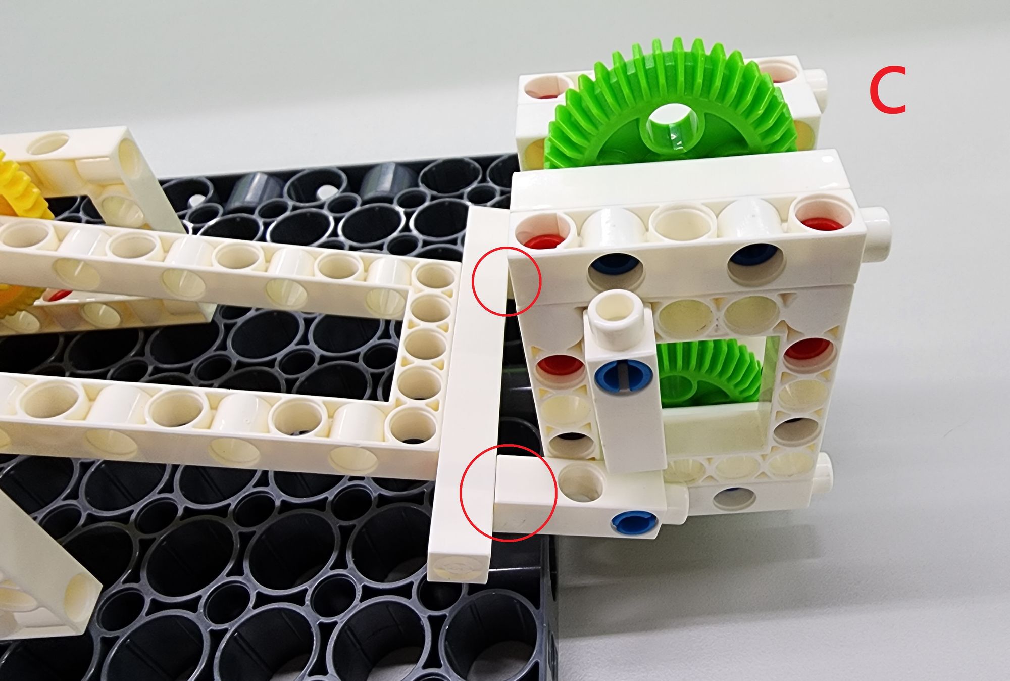
Next, we use the C-40T SPINDLE GEAR (7408-W10-D1G) (Figure 14). We need to add the symmetrical parts onto the left and right sides of the two C-40T SPINDLE GEAR, like a sandwich, complete the part C (Figure 15). The two C-40T SPINDLE GEAR on the upper and lower parts of this part can mesh with the threaded rod to make horizontal displacement.
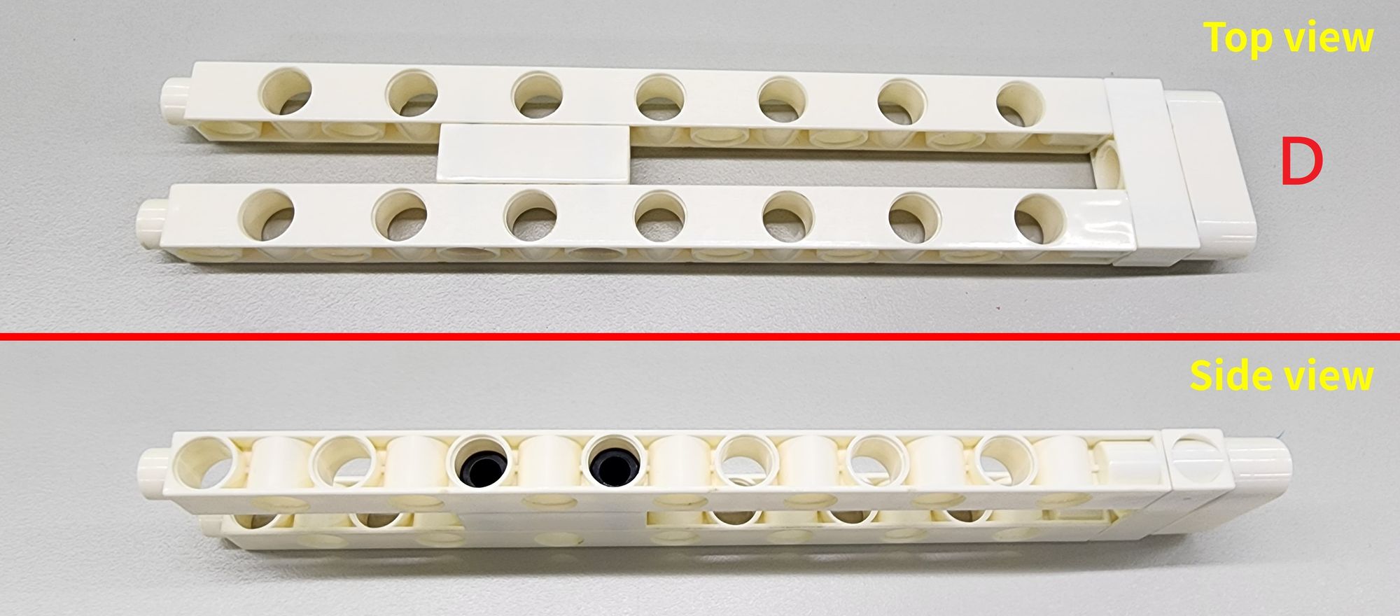
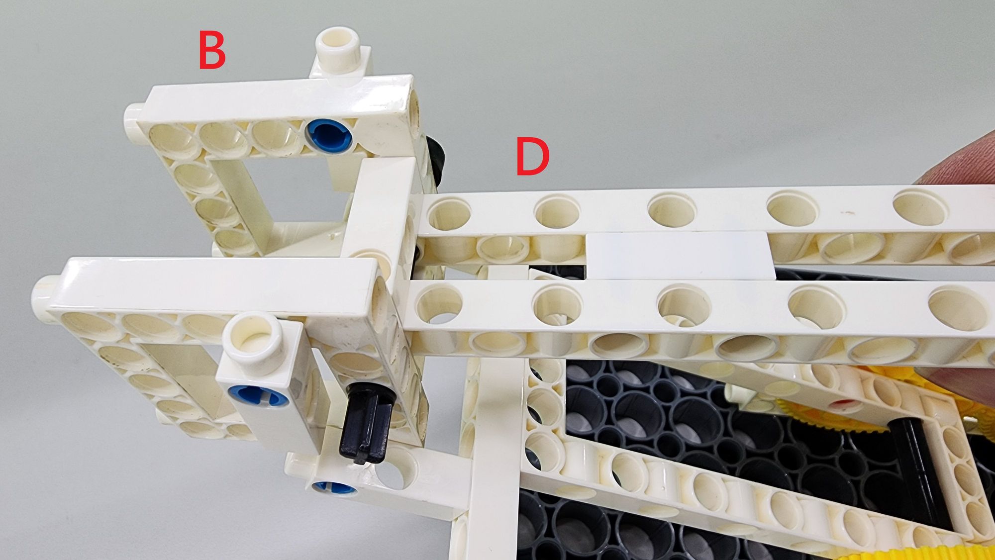
Step 5: we now need to make a threaded rod, which consists of part D and part E. First use two C-15 HOLE DUAL ROD, two C-3 HOLE ROD, a C-3 HOLE ROUND ROD and B-SHORT PEG (Figure 16). Place them as shown in the figure. Here is the part D (Figure 17), which is used to make up for the distance between the spiral part and the retainer (part B).
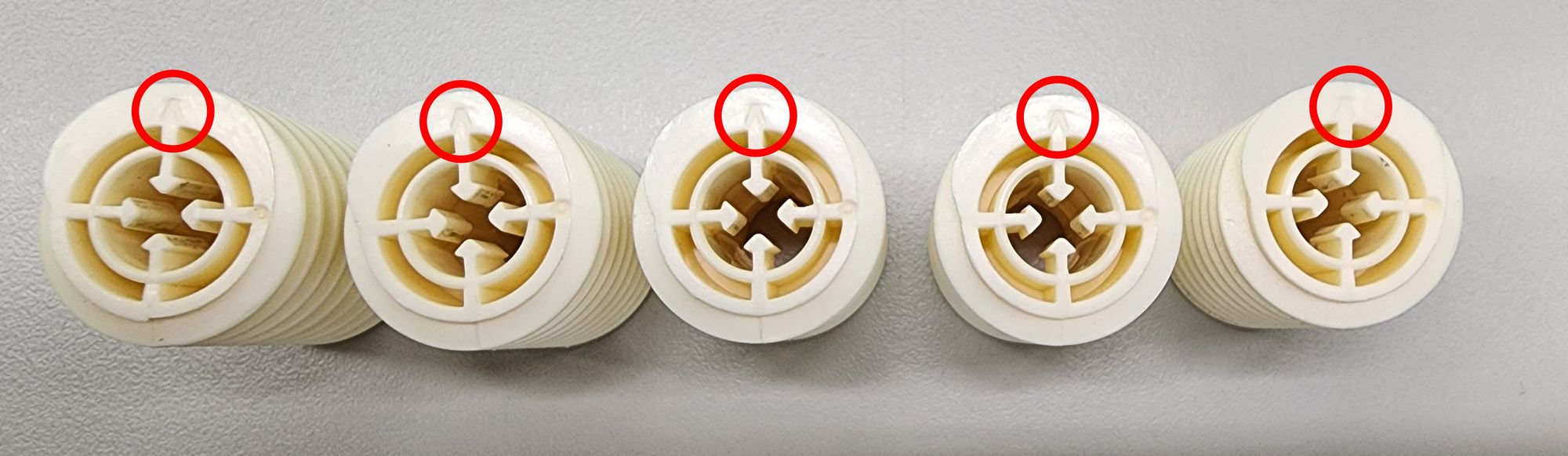
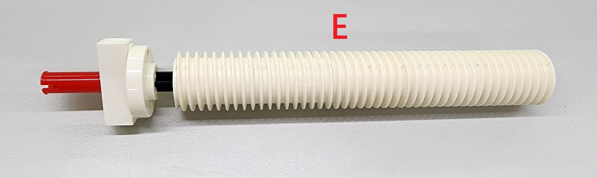
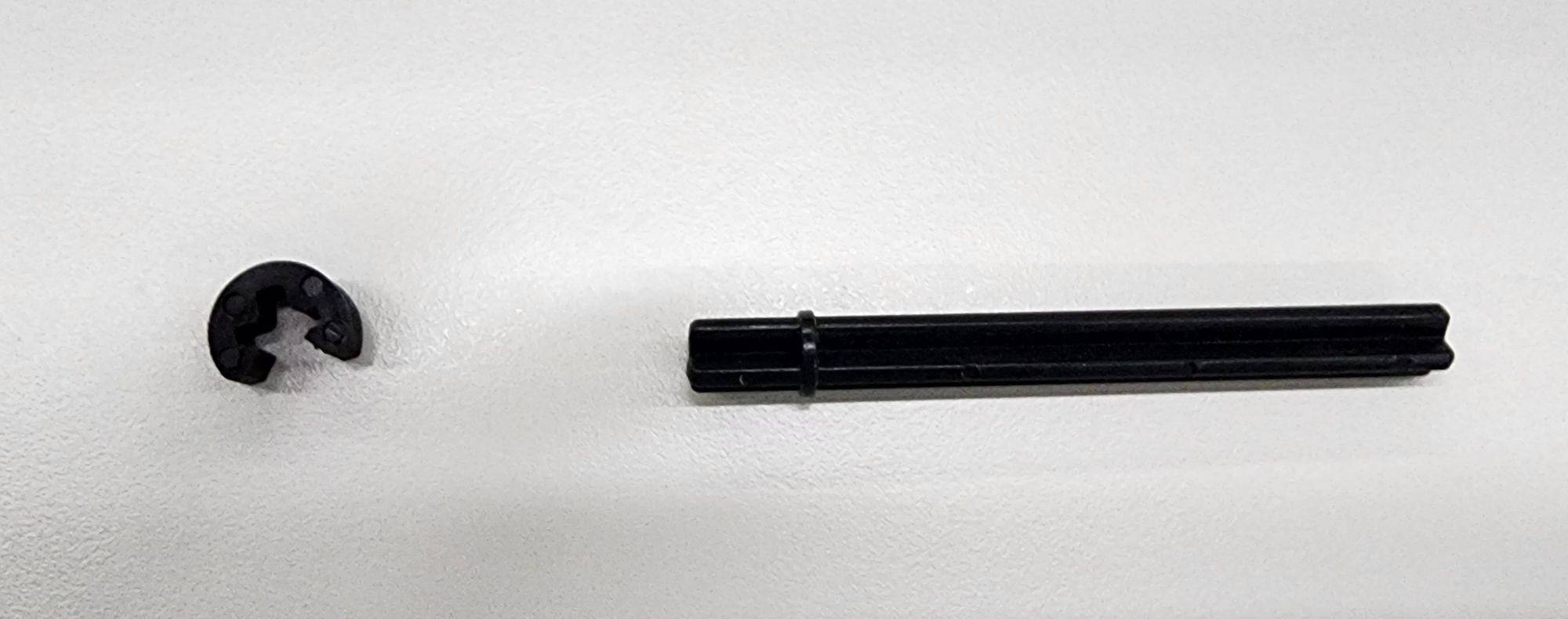
Next, we use the C-150mm AXLE, C-WORM GEAR, C-3 HOLE ROD, C-ROD CONNECTOR and C-30mm AXLE CONNECTOR (7413-W10-U1R) (Figure 18), connect the C-WORM GEAR together with the C-150mm AXLE. It is necessary to ensure that the marks on the C-WORM GEAR point in the same direction during being docked (Figure 19), so that the threads between the C-WORM GEAR can be perfectly connected. Assemble the remaining parts as shown in the figure to complete the production of part E (Figure 20). This part is capable of meshing with C-40T SPINDLE GEAR.
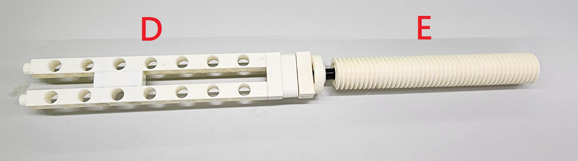
Finally, combine the C-3 HOLE ROD and C-3 HOLE ROUND ROD of part D with the C-30mm AXLE CONNECTOR of part E to complete the production of the threaded rod (Figure 21).
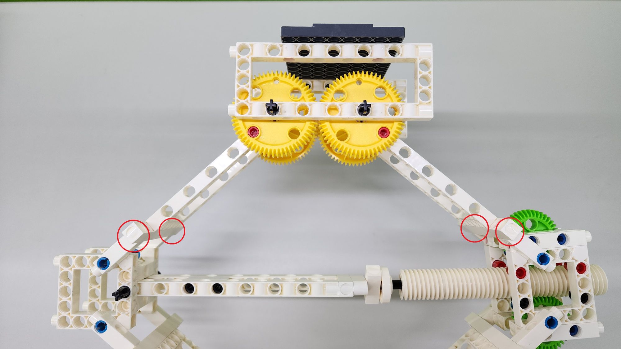
Step 6: we then combine parts B and C with the lower half of the cantilever. Simply combine the C-LONG PEG on the cantilever with the C-3 HOLE DUAL ROD of parts B and C (Figures 22 and 23).
Step 7: we need to use the C-70mm AXLE and C-AXLE FIXING (Figure 24). Pass the C-70mm AXLE through the holes of parts B and D, and fix it with the C-AXLE FIXING to complete the installation of the threaded rod (Figure 25).
Step 8: we then lock the threaded rod into part D. First, align the threaded rod with the upper and lower C-40T SPINDLE GEAR, then rotate the threaded rod so that it slowly enters between the C-40T SPINDLE GEAR (Figure 26).
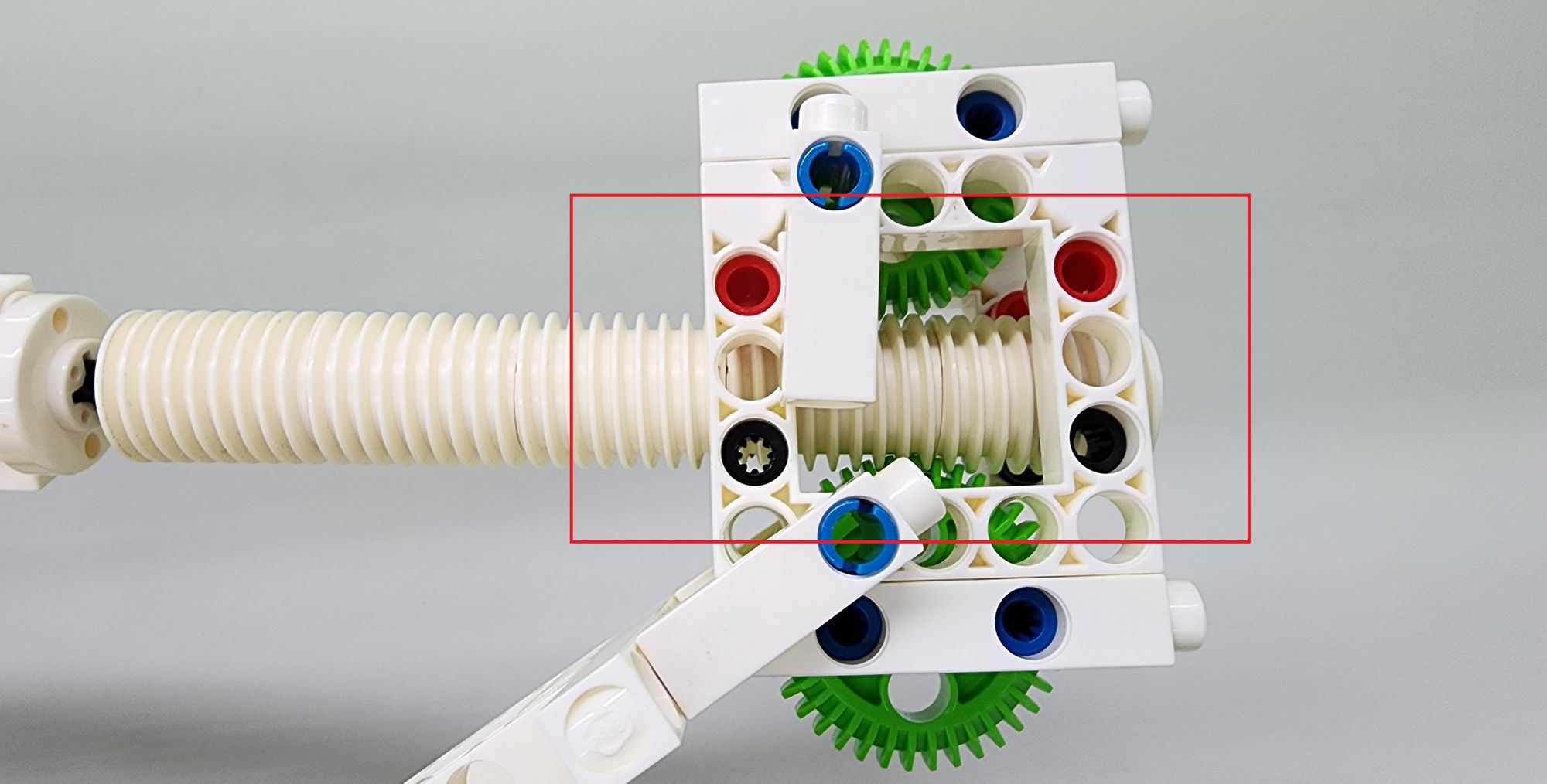
When rotating, it is necessary to confirm that the threaded rod is located between the track composed of long and short pegs (Figure 27). When the threaded rod has completely passed through part D (Figure 28), you can proceed to the next step.
Step 9: we make the load-bearing platform, mainly using the C-BASE GRID, the C-5x13 DUAL FRAME and the C-LONG PEG (Figure 29), and combine them into part F as shown (Figure 30).
Next, to combine the load-bearing platform with the cantilever, we need to use two C-100mm AXLE and the remaining two parts A (Figure 31). Same as the second step. According to the figure, the two C-100mm AXLE will pass through the C-5x13 DUAL FRAME on the load-bearing platform and two parts A to complete the production of the upper half of the cantilever. Then also confirm that the 60T gears of the two cantilevers mesh with each other and the cantilever heights are the same (Figure 32).
The last step is to combine parts B and C with the upper half of the cantilever. Same as step 6, combine the C-LONG PEG on the cantilever with the C-3 HOLE DUAL ROD of parts B and C (Figure 33).
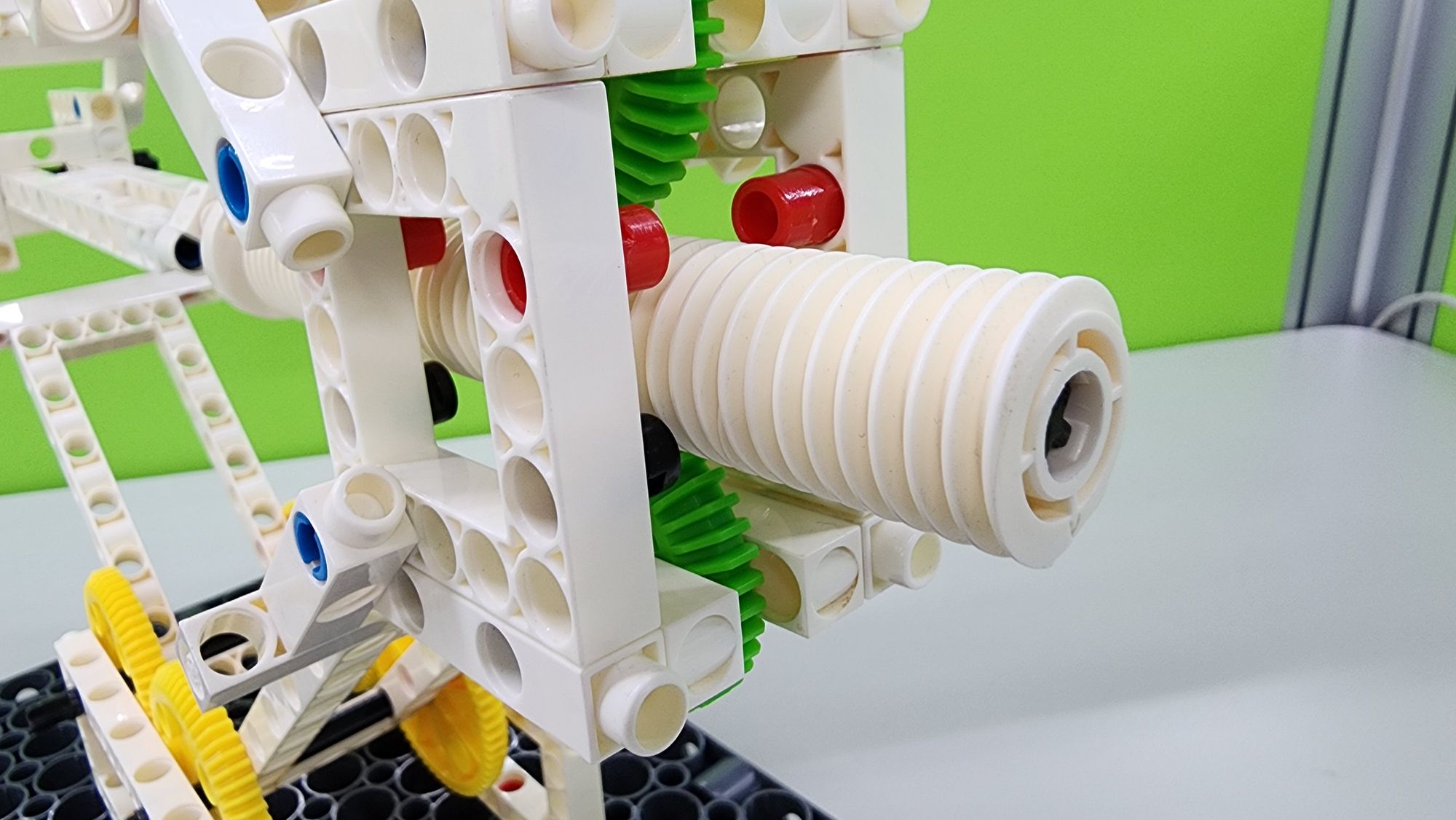
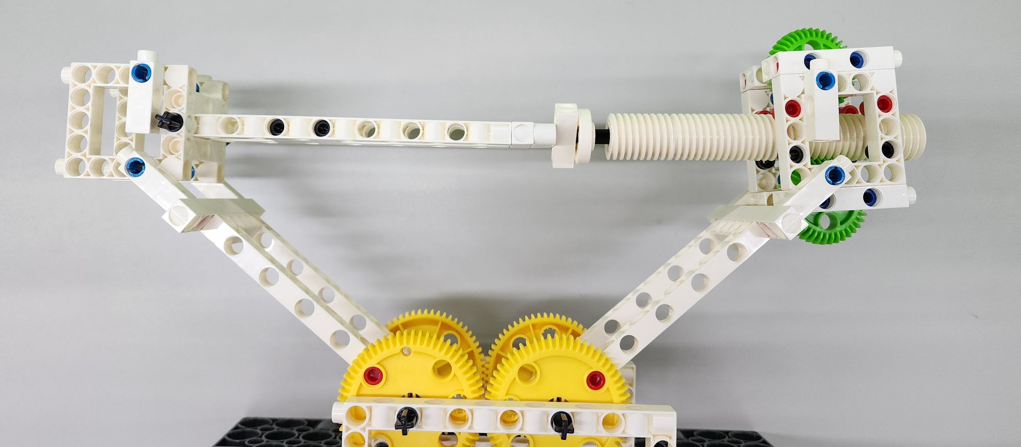
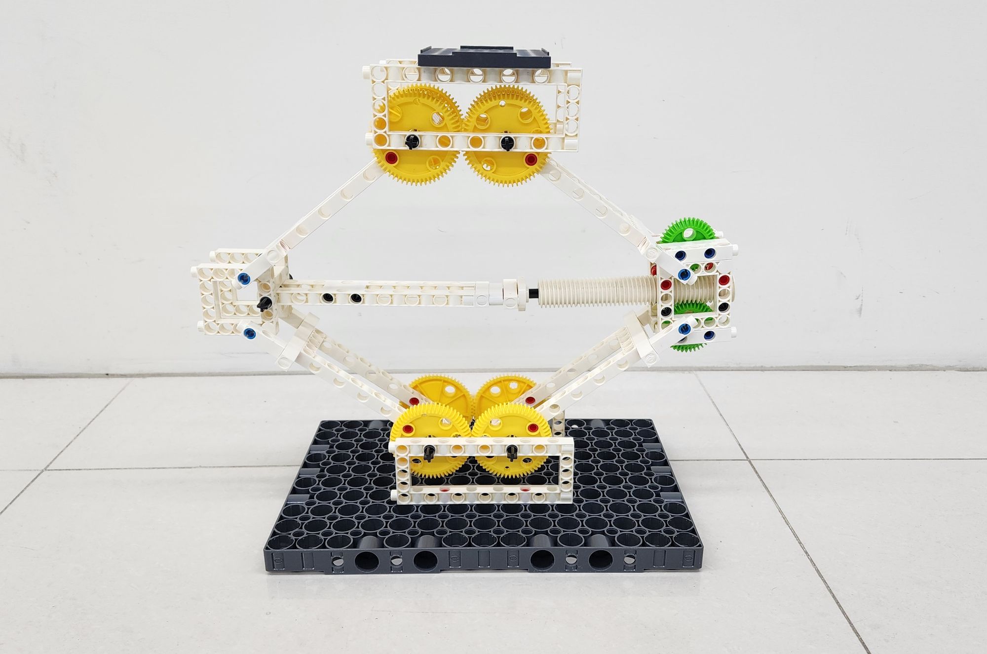
This completes the jack model (Figure 34), now let’s test it to see how it works (Video 1)!
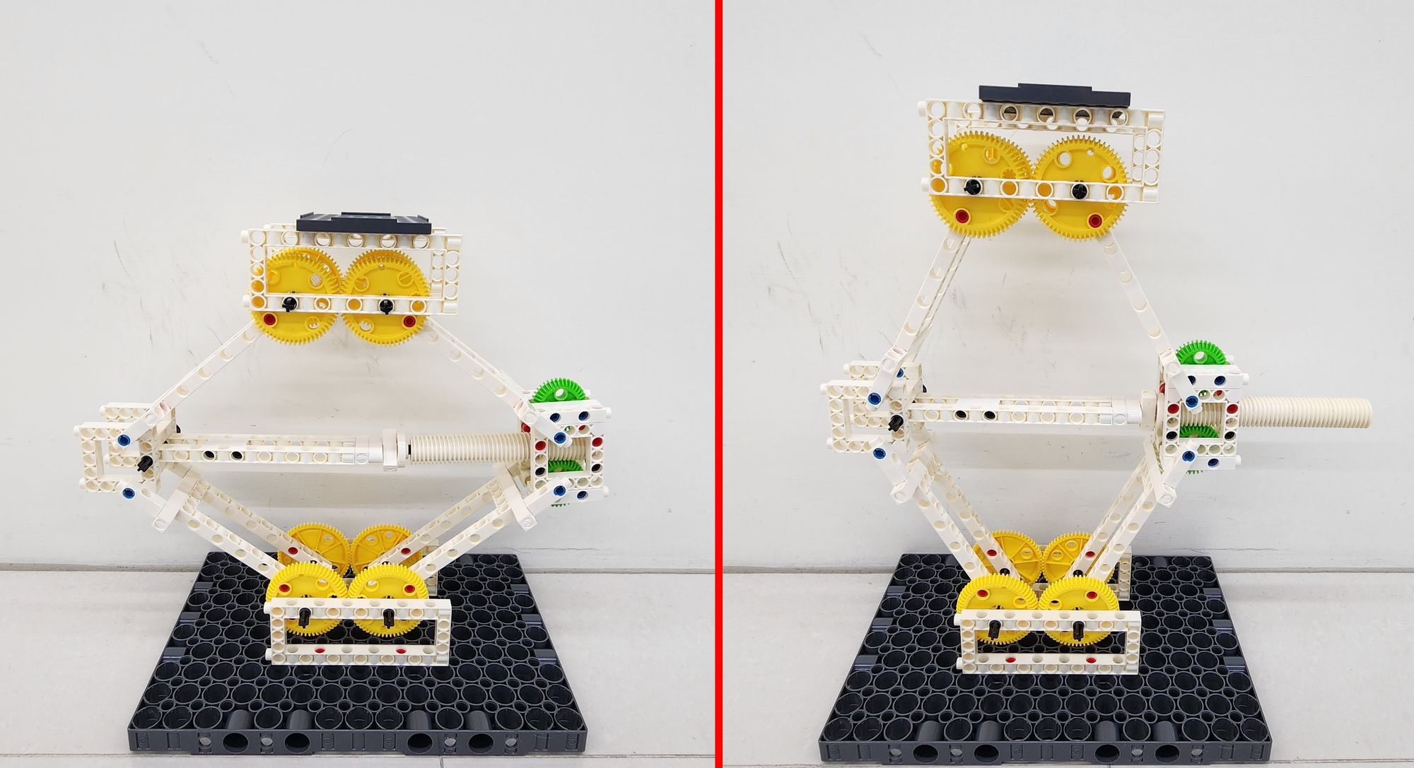
By the comparison in the figure (Figure 35), we can find that the length of the threaded rod is closely related to the height of the jack. When we rotate the threaded rod counterclockwise to move it to the right, the load-bearing platform can rise. On the contrary, when we rotate the thread clockwise, When the lever moves to the left, the load-bearing platform can be lowered. You can try putting different items on the jack and test to see how heavy the jack can lift.
◆Conclusion
When operating the model of a jack, you will notice that it has limited lifting space. This is related to the length of the threaded rod. The longer the threaded rod, the greater the lifting range of the jack. Since the longest axle of the Gigo building blocks is only 15 centimeters, we can only create a 15-centimeter worm gear at most. This limits the lifting range of the jack. However, this length is sufficient to accurately simulate the operation of the jack. Try to think about whether there is a way to modify the model to extend the worm gear further.
That's it for today's sharing. If you enjoyed this article, please share it with others. See you next time, goodbye!
◆ Scientific Principles
The jack mainly utilizes the principles of simple machines, including the screw principle and the worm gear structure (Video 2). The concept of the screw dates to ancient Greece and is one of the six simple machine concepts. Screw threads are commonly used in everyday items like screws, corkscrews, and bottle caps. The worm gear structure combines screw threads and gears, where the rotating axle with threads is known as the worm, and the gear is called the worm wheel. In the realm of simple machines, the slower the gear reduction, the greater the force that can be generated. The worm gear structure is an extreme form of gear reduction, as when the worm rotates one full turn, the worm wheel only moves one tooth's distance. This jack makes use of the properties of the worm gear structure. By rotating the threaded rod (worm), the jack's structure is altered to create different height differences, thus lifting heavy objects.
◆Curriculum(NGSS):
K-2-ETS1-1 Engineering Design
K-PS2-2 Motion and Stability: Forces and Interactions
HS-PS3-3 Design, build, and refine a device that works within given constraints to convert one form of energy into another form of energy.
#Gigo#Gigo Lab#Learning Lab#Fun Lab
◆Reference:
 Contributors to Wikimedia projects
 Contributors to Wikimedia projects
 Contributors to Wikimedia projects
 Contributors to Wikimedia projects
Please sign in to vote.