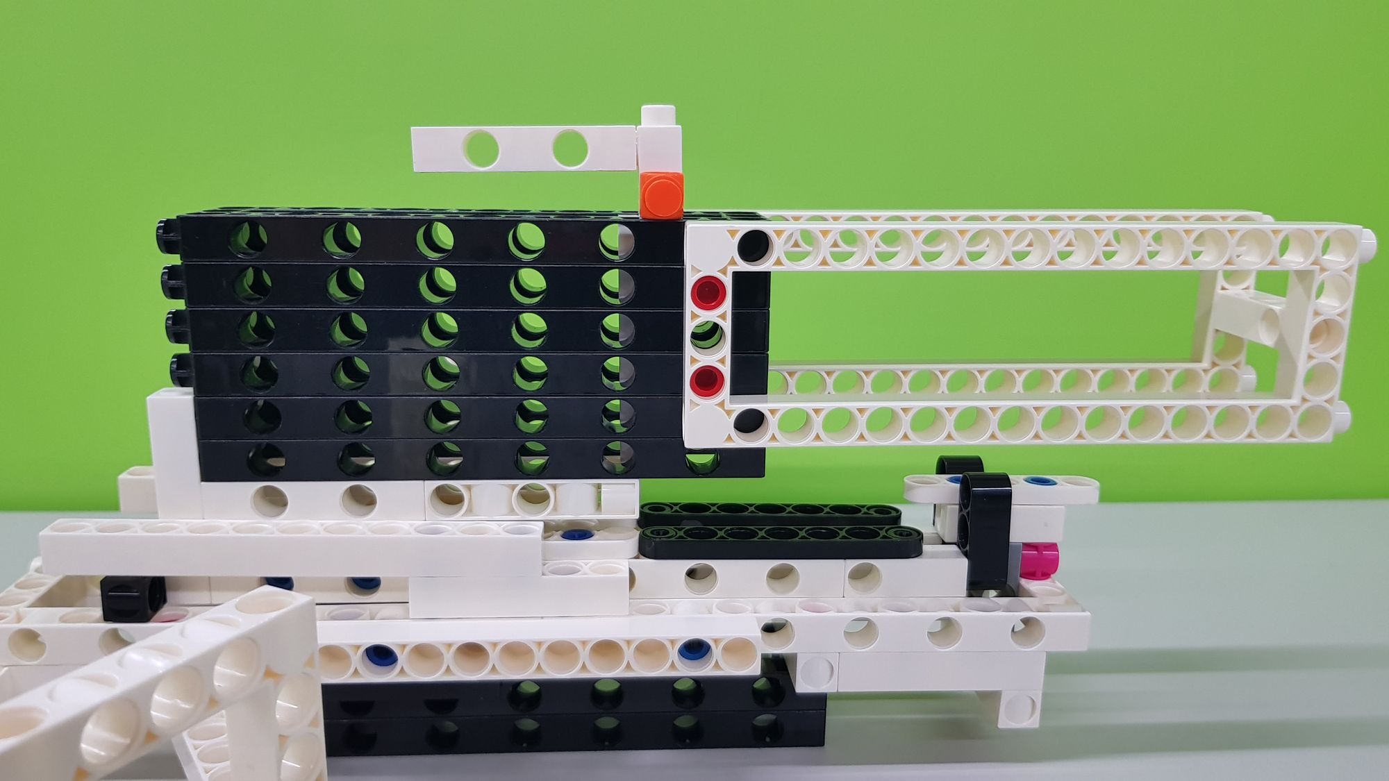
Science in daily life: EP5 - [China's ancient technology] Zhuge Crossbow

![Science in daily life: EP5 - [China's ancient technology] Zhuge Crossbow](/content/images/size/w2000/2023/06/20230306_133155.jpg)
Hello everyone, it's Teacher Raccoon! When we think of technologically advanced countries, we often consider Western nations like the United States or Germany. However, if we go back thousands of years, we'll discover that China was once at the forefront of scientific and technological advancements. Inventions like the armillary sphere and movable type printing, as well as notable works like 'Tiangong Kaiwu' (The Exploitation of the Works of Nature) and 'Bencao Gangmu' (Compendium of Materia Medica), are widely recognized. Today, Teacher Raccoon will demonstrate how to create a remarkable ancient Chinese weapon, the Zhuge crossbow, which was considered a marvel of technology at that time.
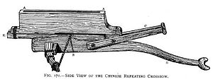
Crossbow was first invented in the Warring States Period, and it was improved by Zhuge Liang in the Three Kingdoms Period, so it is also called Zhuge Crossbow. It is not necessary to fill the arrows immediately after firing (Video 1), now let Teacher Raccoon show you how to make the Zhuge Crossbow step by step!
◆Assembly Steps
First of all, we are going to make the main body of the Zhuge Crossbow, including the handle, the launching bump and the crossbow.
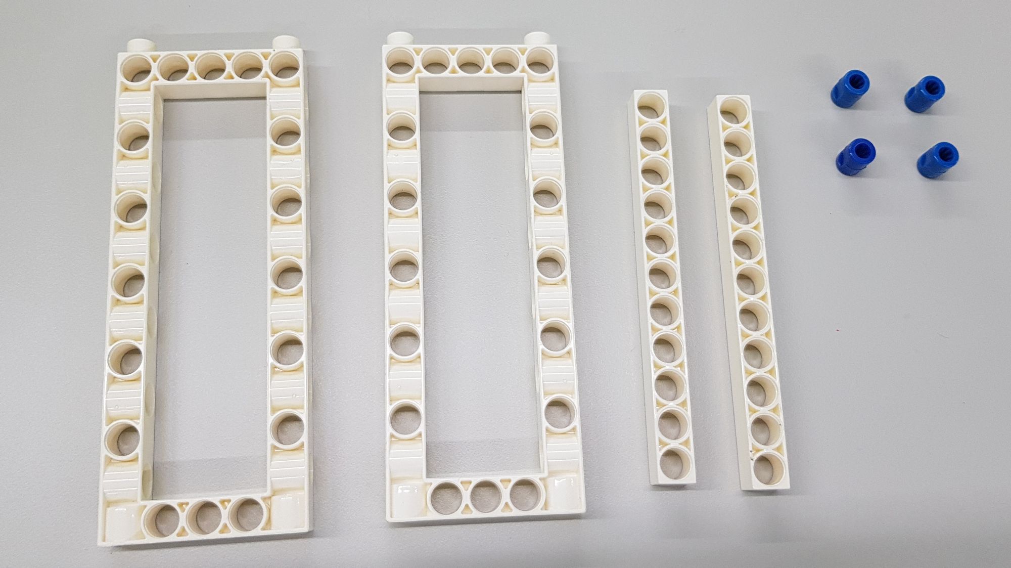
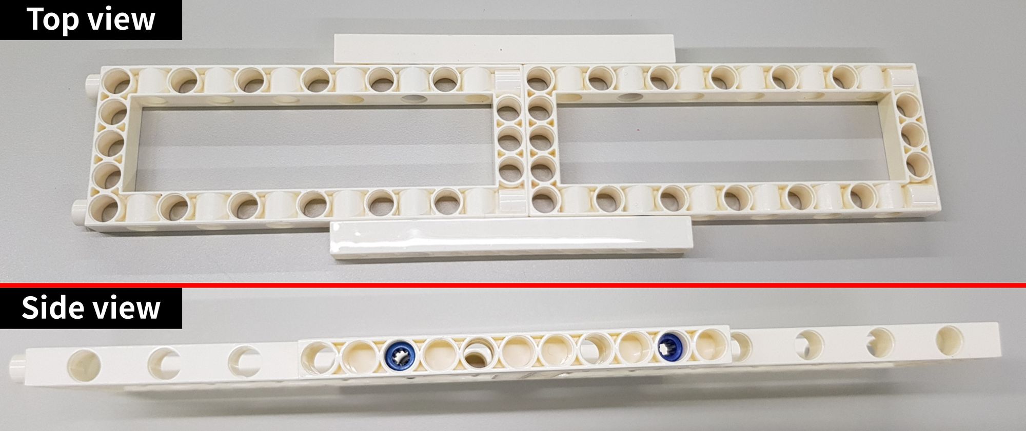
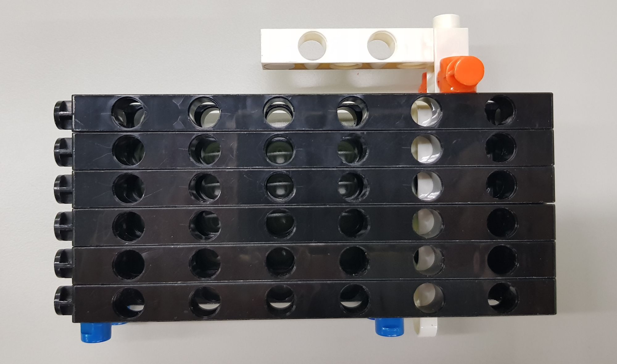
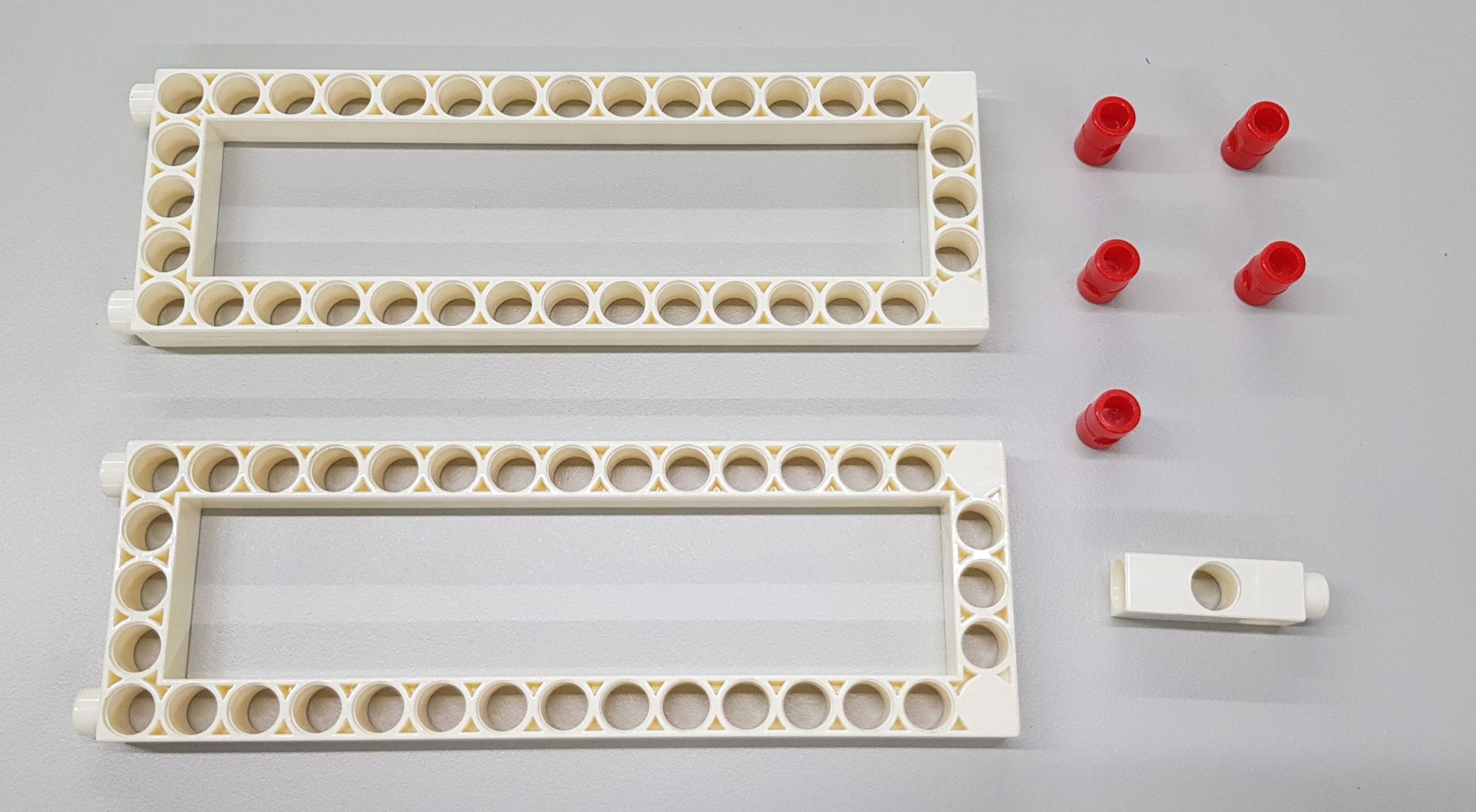
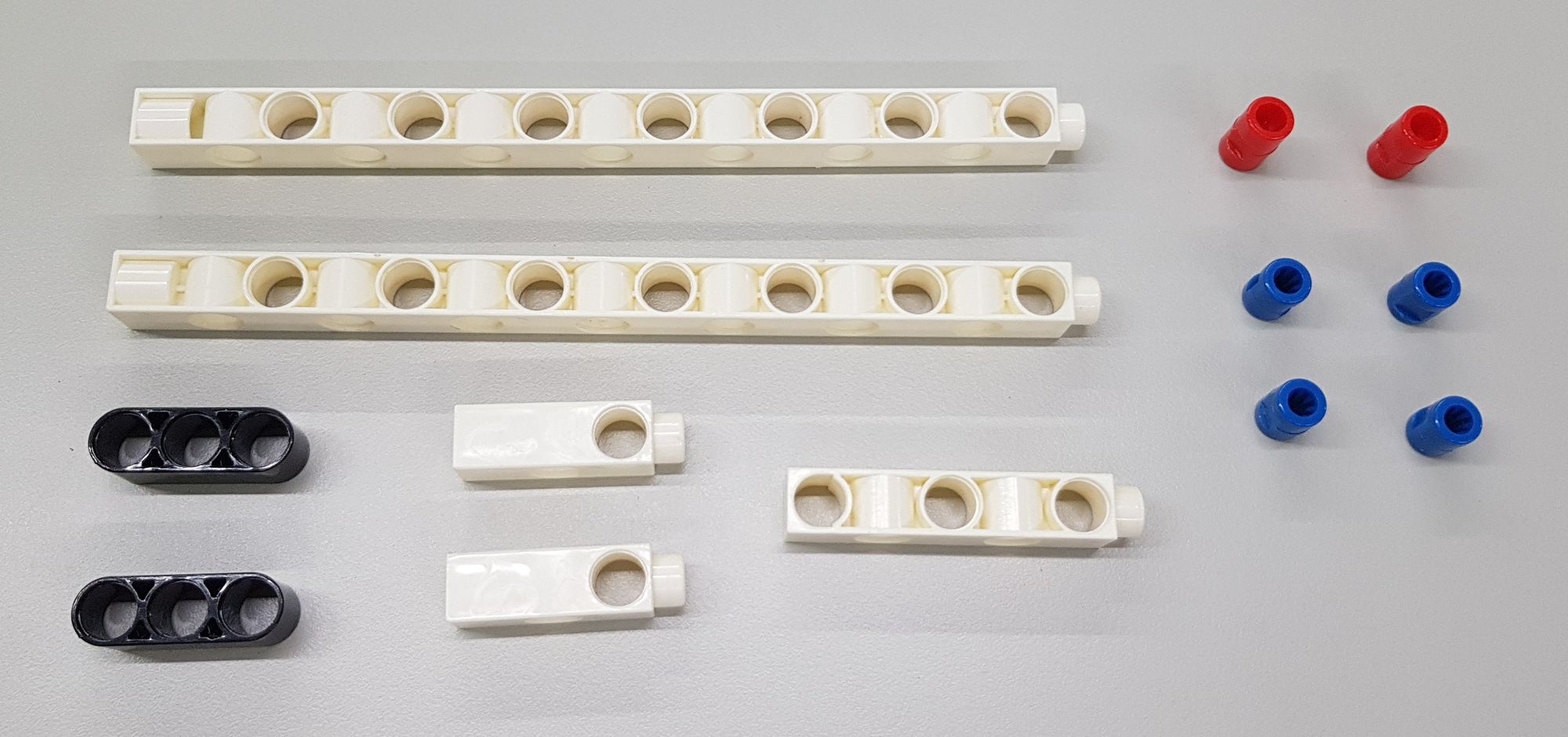
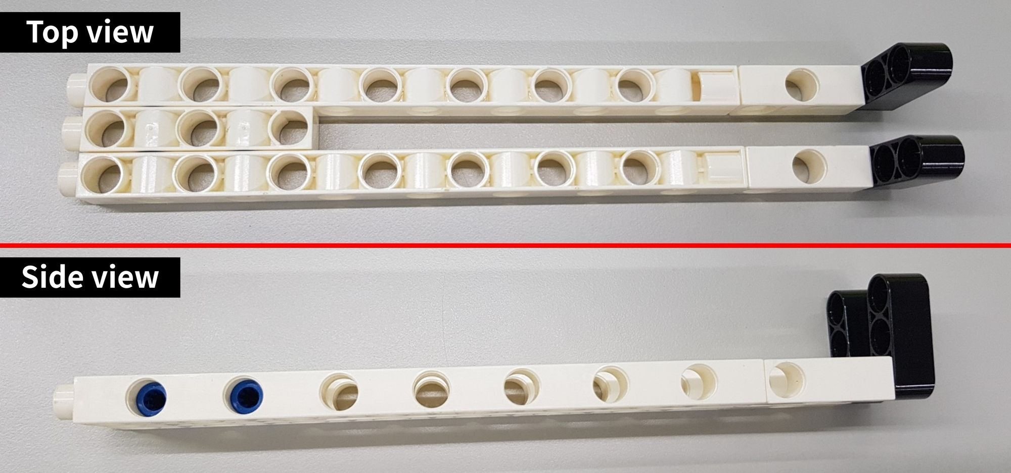
Step 1: We connect the C-5x13 DUAL FRAME, C-11 HOLE ROD and B-SHORT PEG (Figure 1), and use the C-11 HOLE ROD and B-SHORT PEG for reinforcement (Figure 2).
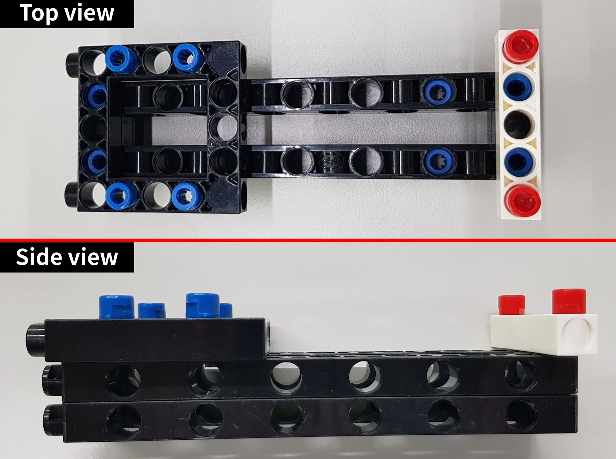
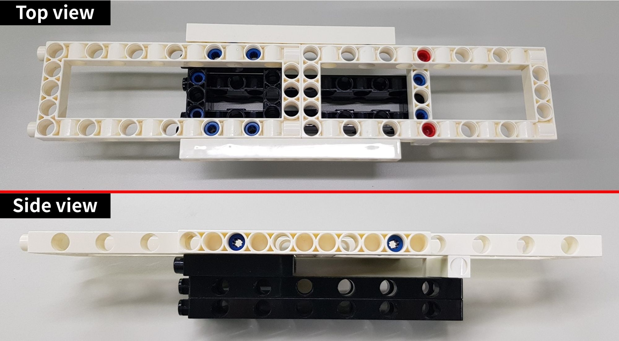
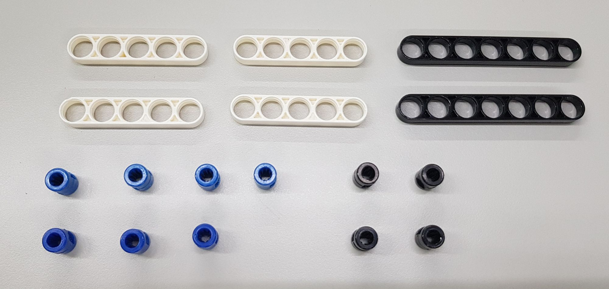
Step 2: We will use the C-LONG PEG and B-SHORT PEG, C-5 HOLE ROD, C-5x5 FRAME and a rare part: C-3x13 DUAL FRAME (7406-W10-A1D) (Figure 3), and then we assemble them as shown (Figure 4).

Then we can combine the two parts of Step 1 and Step 2, so the main body and handle structure of the Zhuge Crossbow is done (Figure 5).
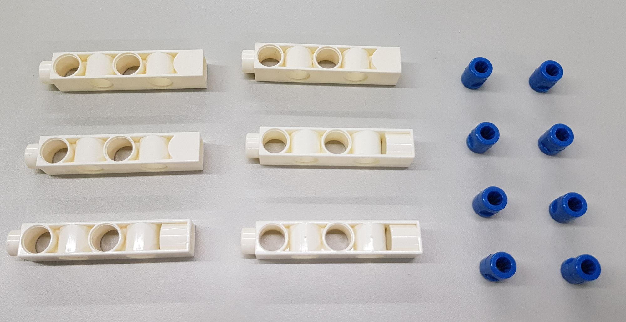
Step 3: We use the C-1 HOLE CONNECTOR (7430-W10-B1W), C-LONG PEG, B-SHORT PEG, C-5 HOLE PROLATE ROD (7443-W10-C1W) and various rods (Figure 6). Make them into two parts A and B as shown (Figure 7).

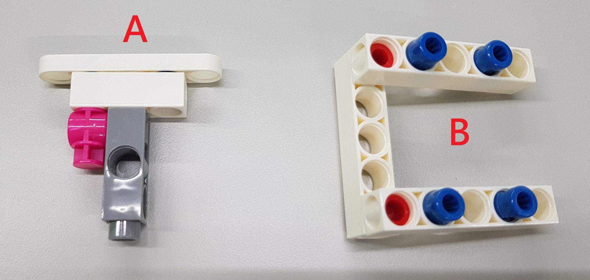
After that, we install parts A and B at the end of the main body, and complete the design of the launch bump (Figure 8).

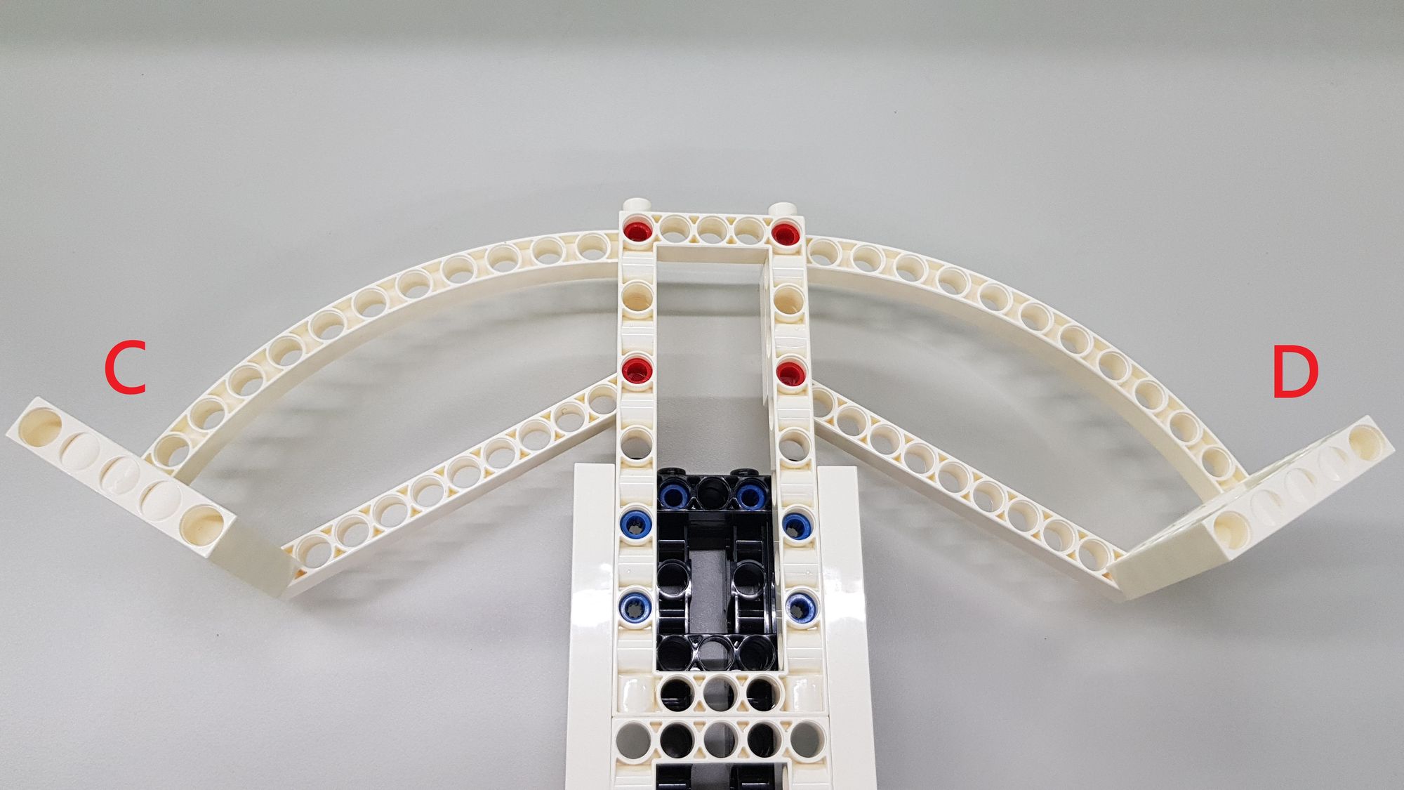
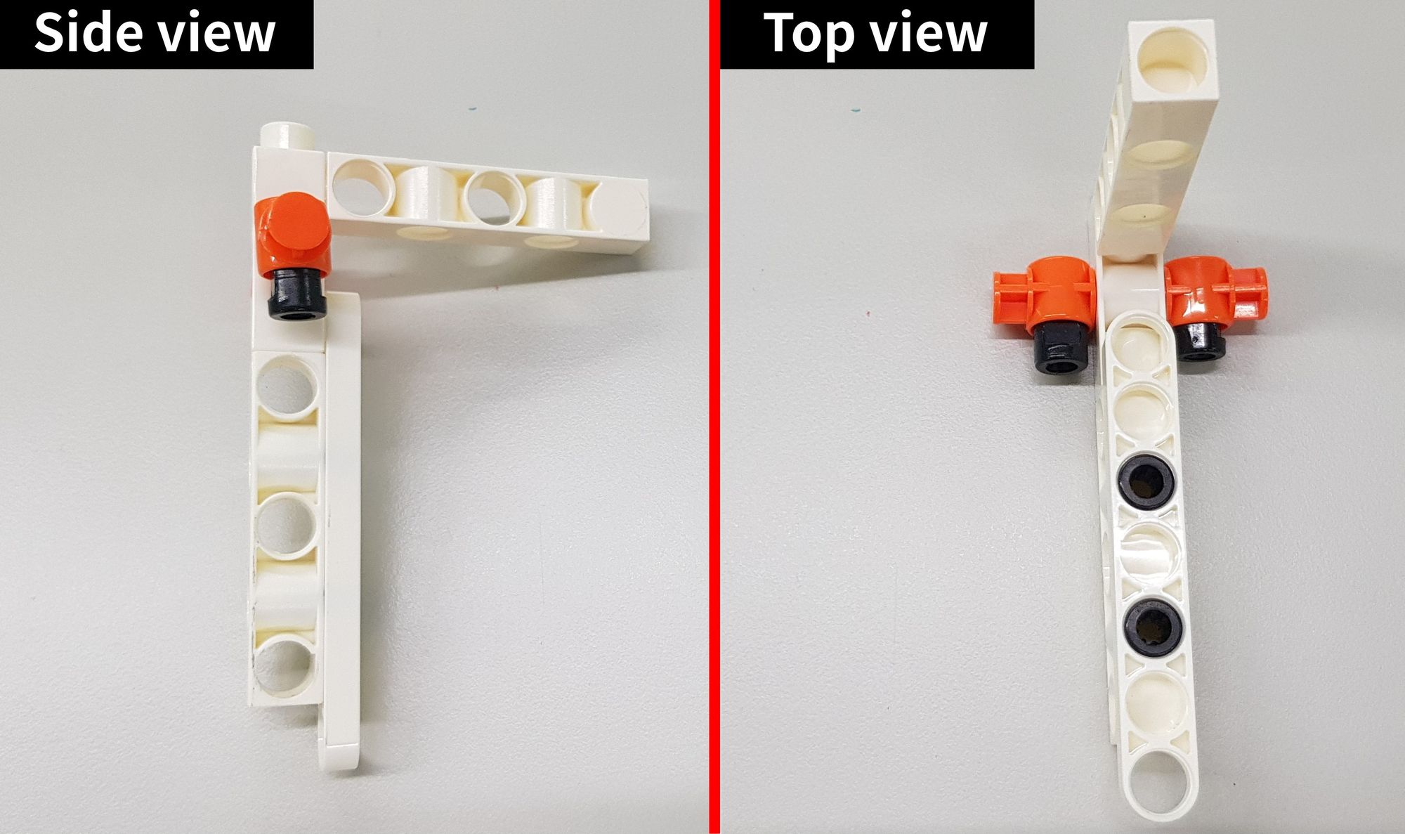
Step 4: We use the C-5x11 CURVED FRAME (7392-W10-I1W), C-5x5 FRAME and C-LONG PEG (Figure 9), and compose them into parts C and D (Figure 10).


Then respectively install part C and part D under the main body to complete the crossbow (Figure 11).
Step 5: We combine the C-5 HOLE ROD, the C-11 HOLE ROD and the B-SHORT PEG (Figure 12) into two identical parts as shown (Figure 13).

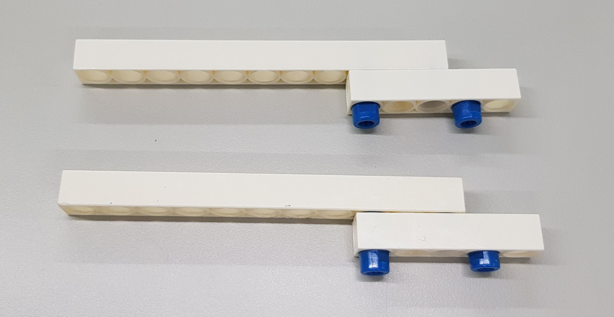
These two parts are mainly used as tracks to prevent the flight groove from falling off the main body during sliding, and the completed two tracks are installed on the left and right sides of the main body (Figure 14).
Then we will start to make the flight groove, which is the most important structure of the Zhuge Crossbow. It can be divided into the upper part for storing arrows and the lower part for fixing the rubber band.
Step 6: We assemble the upper part of the flight groove, using a C-3x13 DUAL FRAME and B-SHORT PEG (Figure 15) to create a space that can store arrows (Figure 16).


Step 7: We use the C-1 HOLE CONNECTOR, the C-7 HOLE WIDE PROLATE ROD (7404-W10-C3W) and various DUAL ROD (Figure 17), and form them into the parts shown (Figure 18 ).

Then combine it with the upper part of the flight groove (Figure 19). Since the length of the arrow we use is 8 cm, this part can ensure that the length and width of the inside of the flight groove are 8.5cmx1cm. When the arrow is loaded, these arrows will be neatly arranged upwards.
Step 8: We use a C-5x15 FRAME, C-3 HOLE DUAL ROD and C-LONG PEG (Figure 20), and form them into two parts E and F (Figure 21).

Then combine the E and F parts with the upper part of the flight groove (Figure 22). We need to extend the length of the upper part of the flight groove, so that it can be combined with the linkage mechanism later.

Step 9: We make the lower part of the flight groove, which will use the C-3 HOLE ROUND ROD, C-LONG PEG and B-SHORT PEG, and various DUAL ROD (Figure 23), and assemble them as shown (Figure 24).
Step 10: We use the C-5 HOLE PROLATE ROD and C-7 HOLE PROLATE ROD and B-SHORT PEG (Figure 25), and we can form them into three parts G, H, and I (Figure 26).

Then combine the G, H, and I parts with the lower part of the flight groove as shown (Figure 27), so that the lower part of the flight groove will be increased by 0.5 cm due to the flat PROLATE ROD, and a groove for fixing the rubber band is made at the rear.

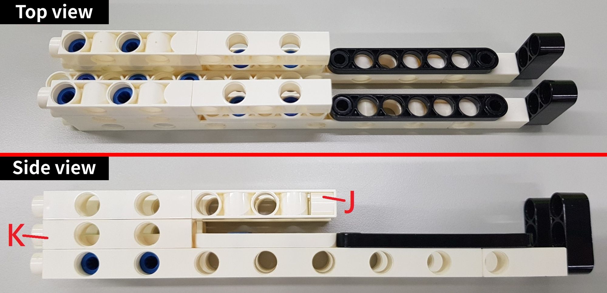
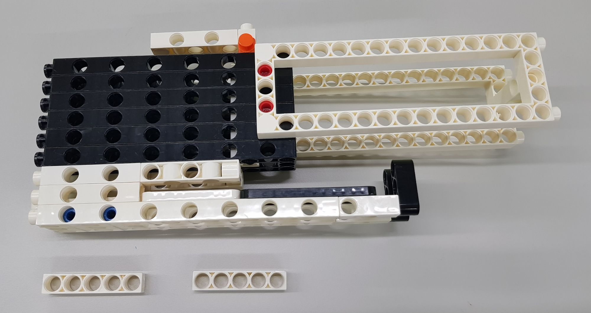
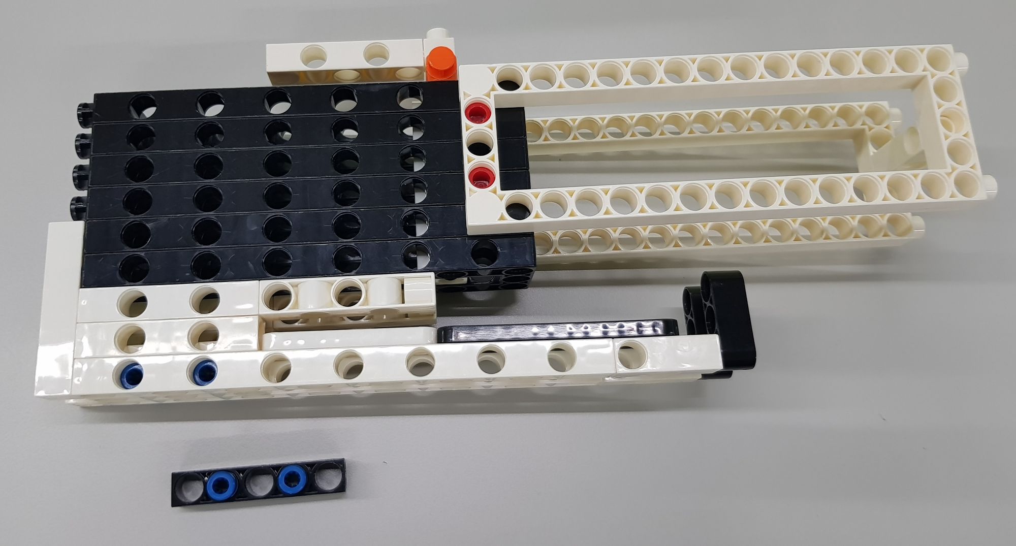
Step 11: We needs to use the C-5 HOLE DUAL ROD and the B-SHORT PEG (Figure 28) to assemble two parts J and K (Figure 29).

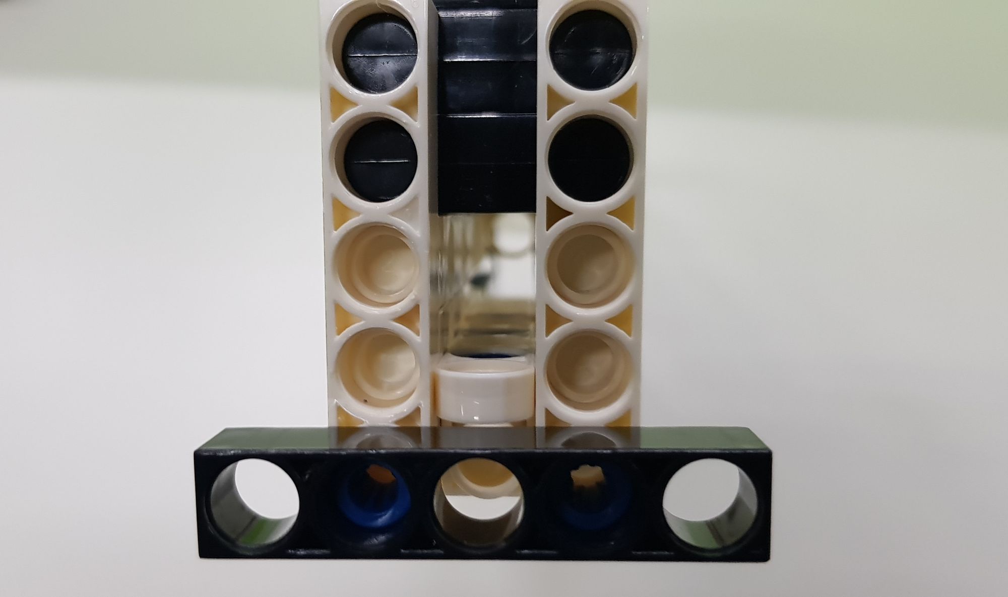
And then, we assemble the J and K parts on the left and right sides of the lower part of the flight groove as shown (Figure 30) to complete the production of the lower half of the flight groove. The J and K parts can be used as baffles to ensure that the arrows will not fall out from the left and right sides when entering the lower part of the flight groove. At the same time, we will keep the 0.5 cm gap in the middle to provide space for the thick rubber band to eject.
Step 12: We need to combine the B-SHORT PEG on the upper part of the flight groove with the lower part of the flight groove (Figure 31), and then use two C-5 HOLE ROD to reinforce it (Figure 32).

Finally, we install a C-5 HOLE ROD on the front end of the flight groove (Figure 33, Figure 34) using a B-SHORT PEG. This C-5 HOLE ROD can slide smoothly in the track of the main body to ensure that the flight groove can be in close contact with the launching bump during it slides to the end.
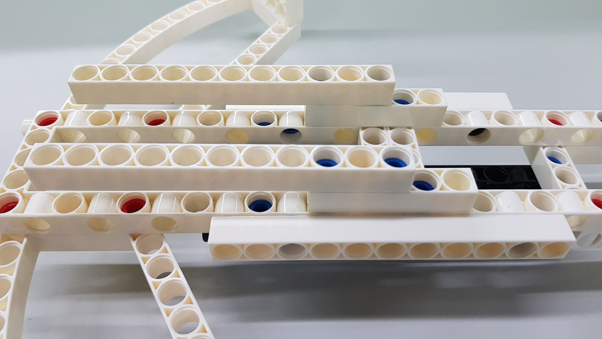
Before proceeding to the next step, we can put the flight groove on the main body to confirm whether the position and length of each part are correct, and then install the linkage (Figure 35).
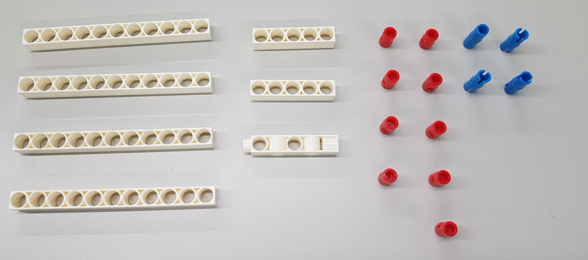
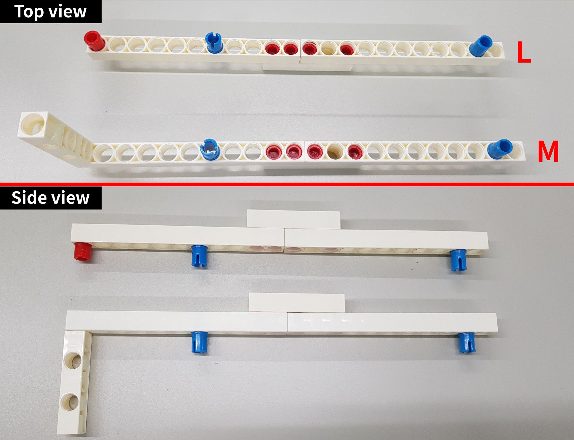
Step 13: We mainly uses C-5 HOLE ROD, C-11 HOLE ROD, C-AXLE CONNECTOR and C-LONG PEG, B-SHORT PEG (Figure 36). We need to combine the parts accordingly to complete the L and M parts of the linkage (Figure 37 ).
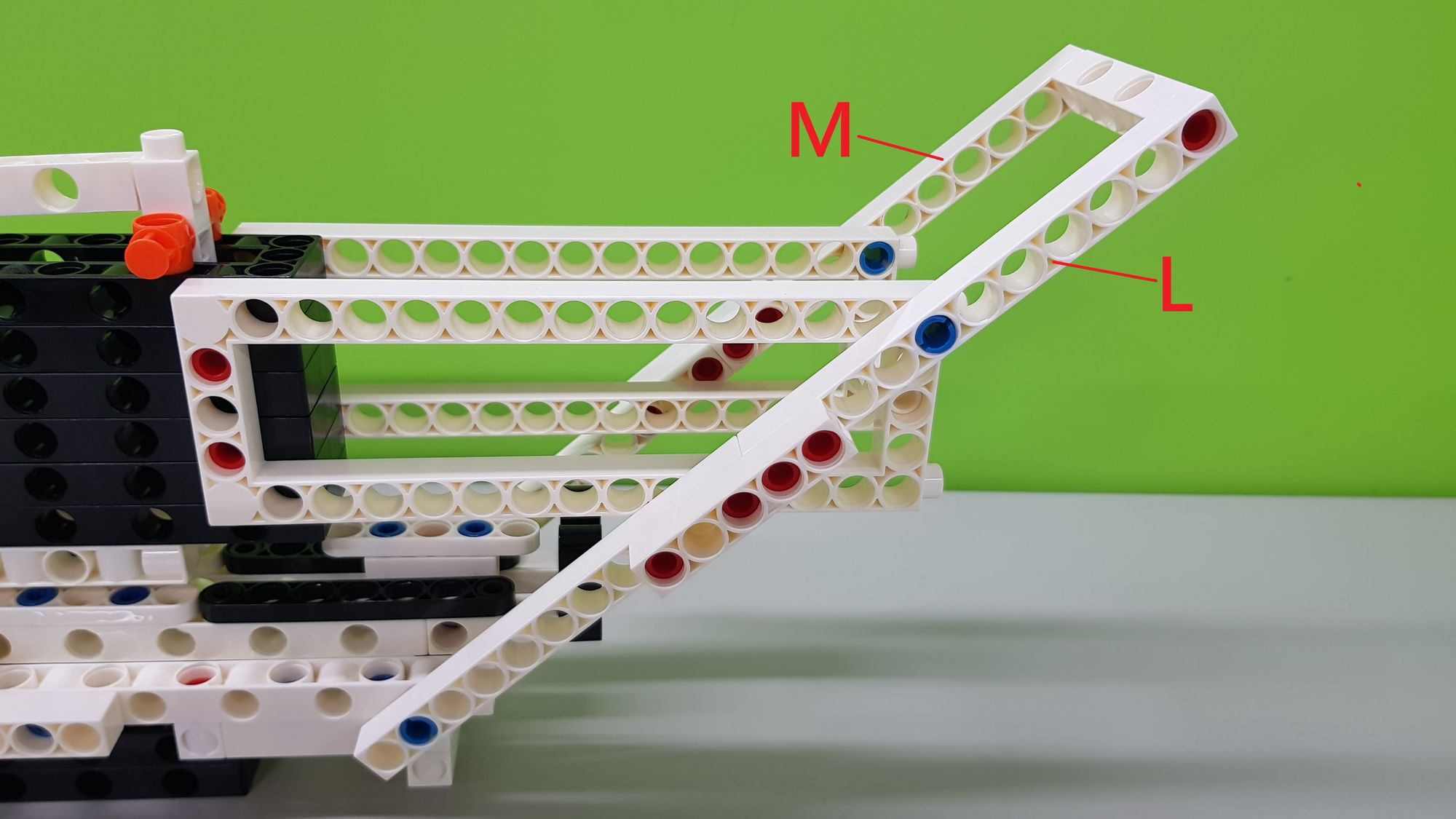
Then we combined the L and M parts, the main body of the crossbow and the flight groove to complete the assembly of the linkage structure (Figure 38).
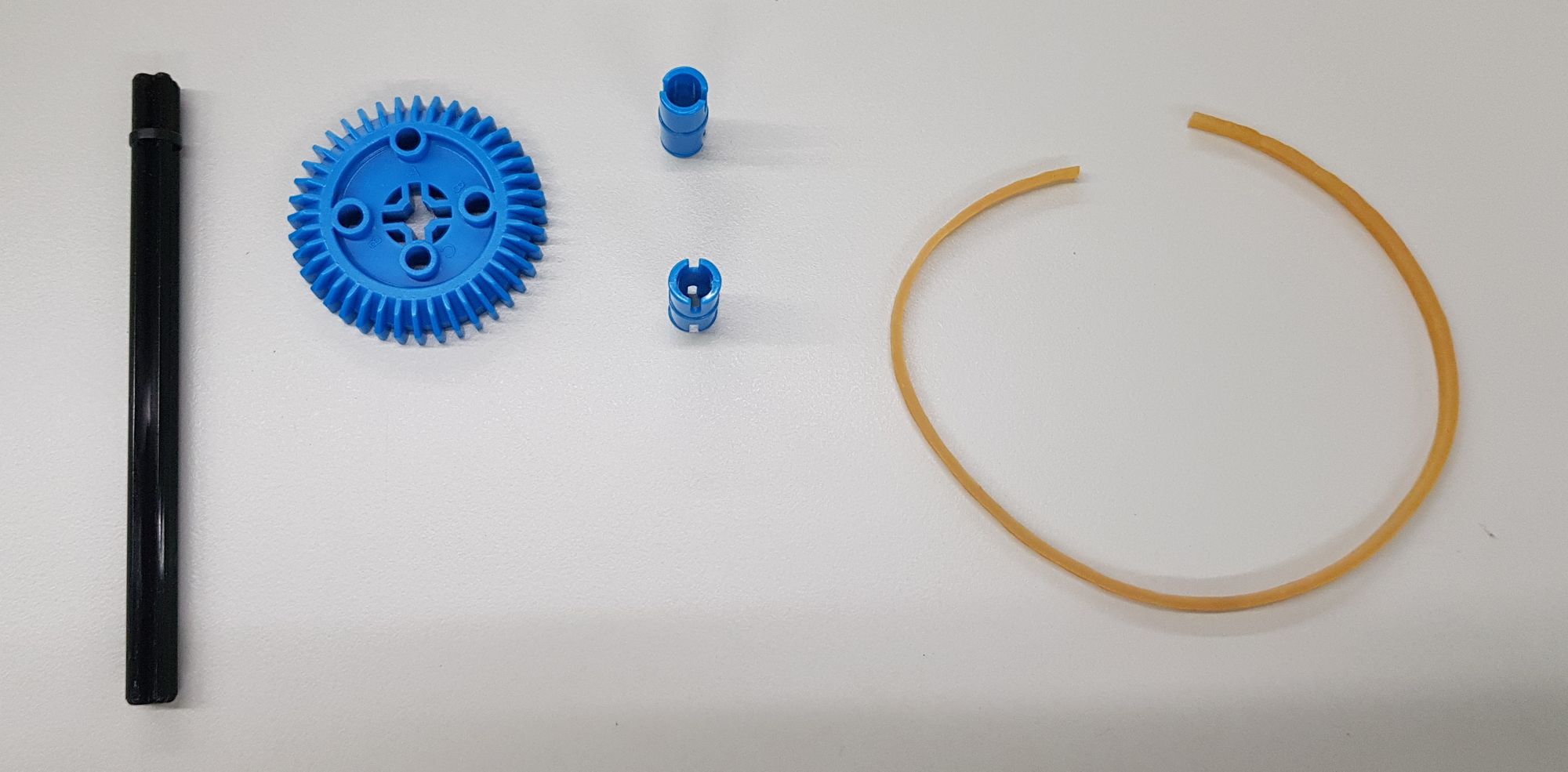
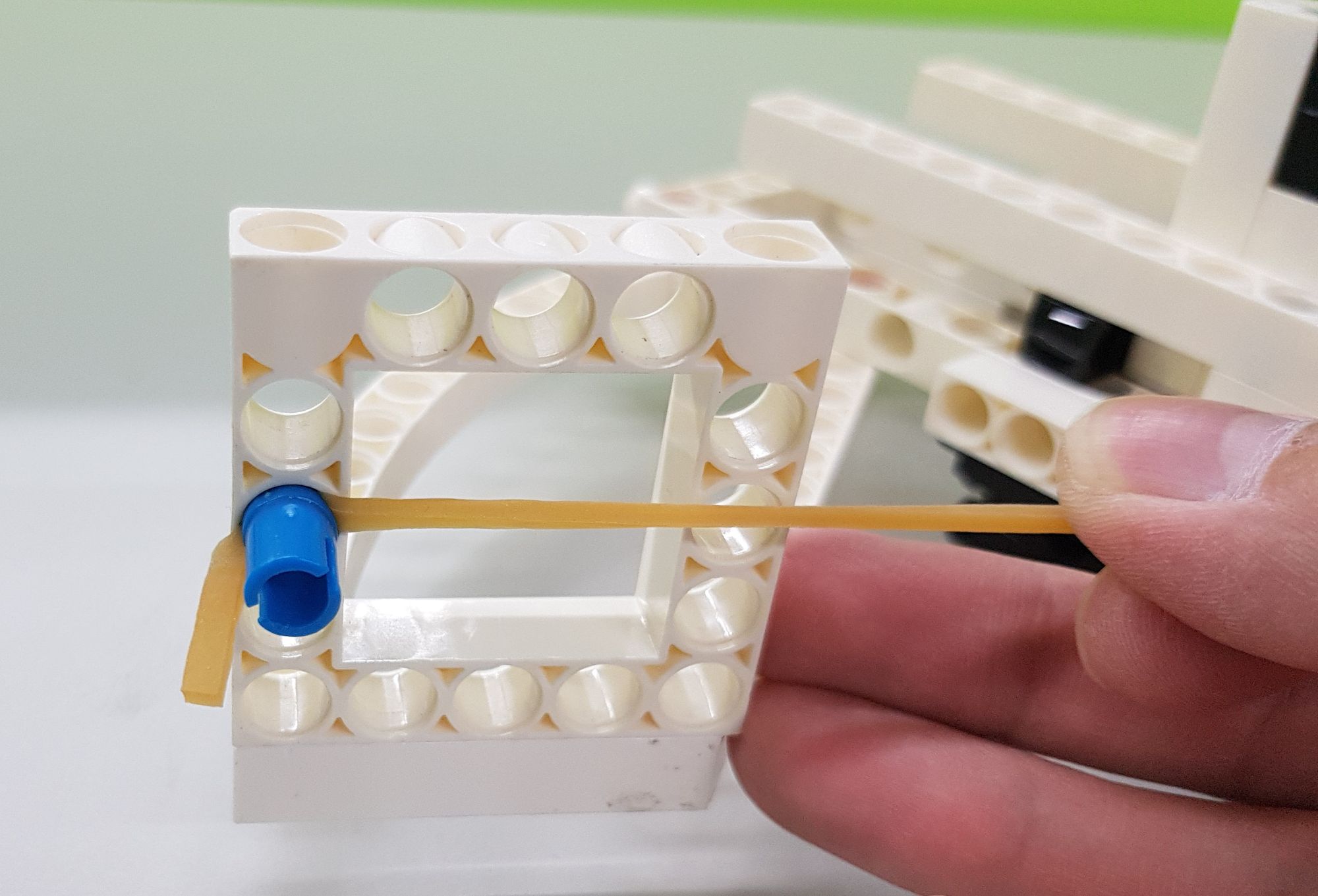
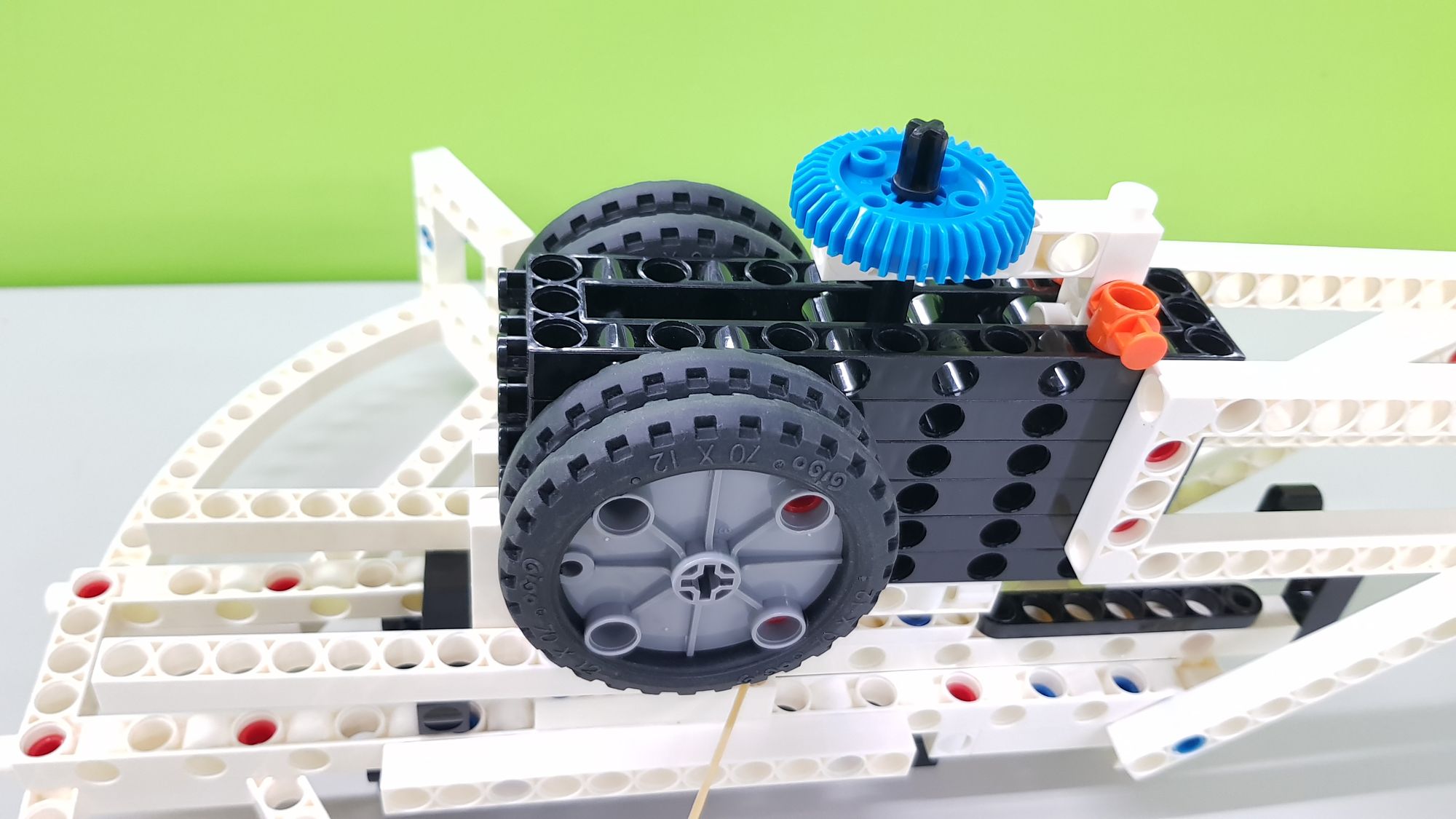
The last step is to use a thick rubber band (can be cut in advance), C-AXLE CONNECTOR, C-100mm AXLE and C-40T GEAR (Figure 39). We can use the C-AXLE CONNECTOR to fix the thick rubber band on the C-5x5 FRAME on the left and right sides of the crossbow frame (Figure 40).
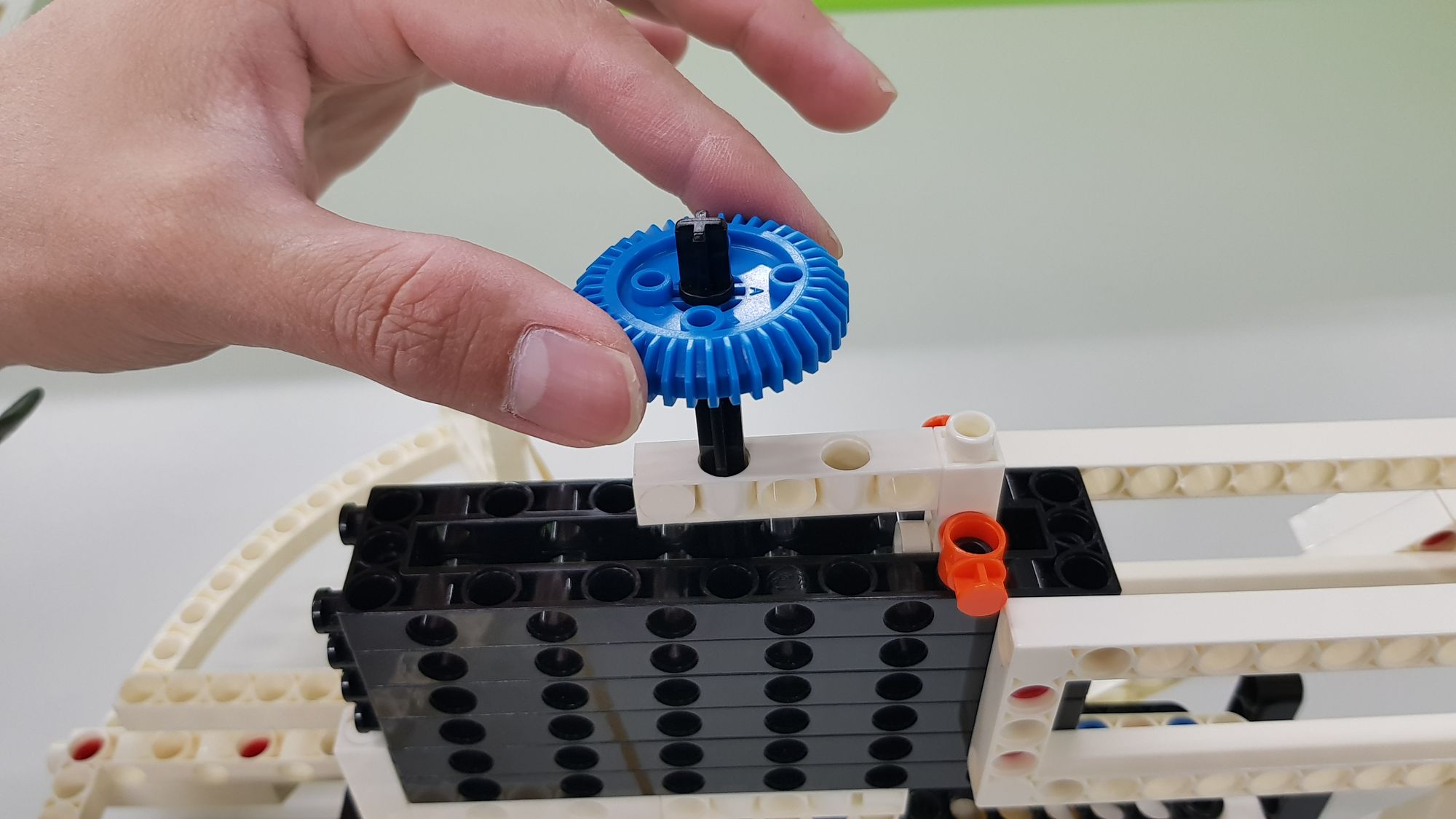
Then we use the C-100mm AXLE and C-40T GEAR to combine into a bullet holder, and put into the holes of the C-5 HOLE DUAL ROD above the flight groove (Figure 41). The bullet holder can press the arrow down to ensure that the arrows in the flight groove can fall more smoothly and contact with the thick rubber band more easily.
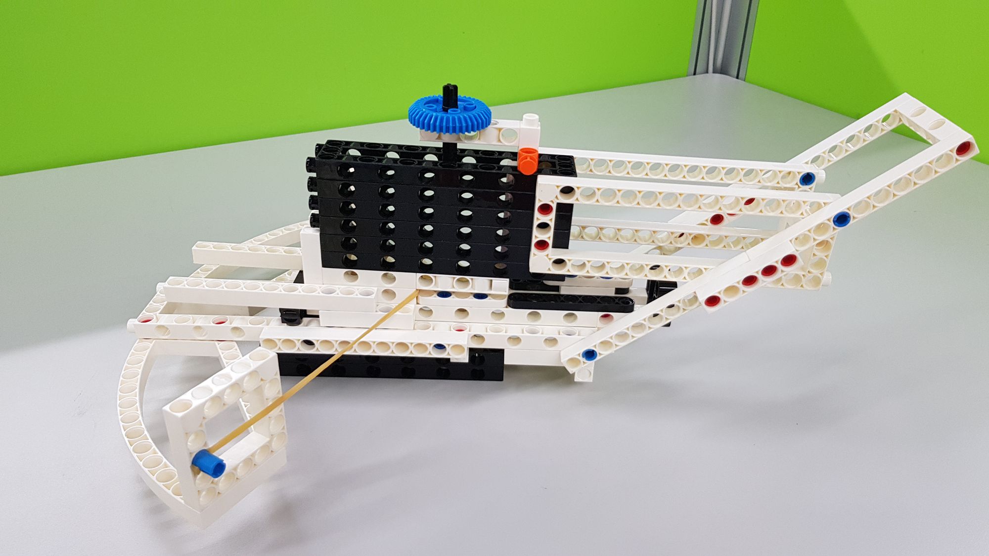
In this way, our Zhuge Crossbow is completed (Figure 42). First, we can test whether the mechanism of the flight groove and the linkage rod is correct. When the linkage is pushed forward, the thick rubber band needs to enter the back gap of the flight groove. When the linkage is pulled back, the thick rubber band fires forward due to contact with the launching bump (Video 2).
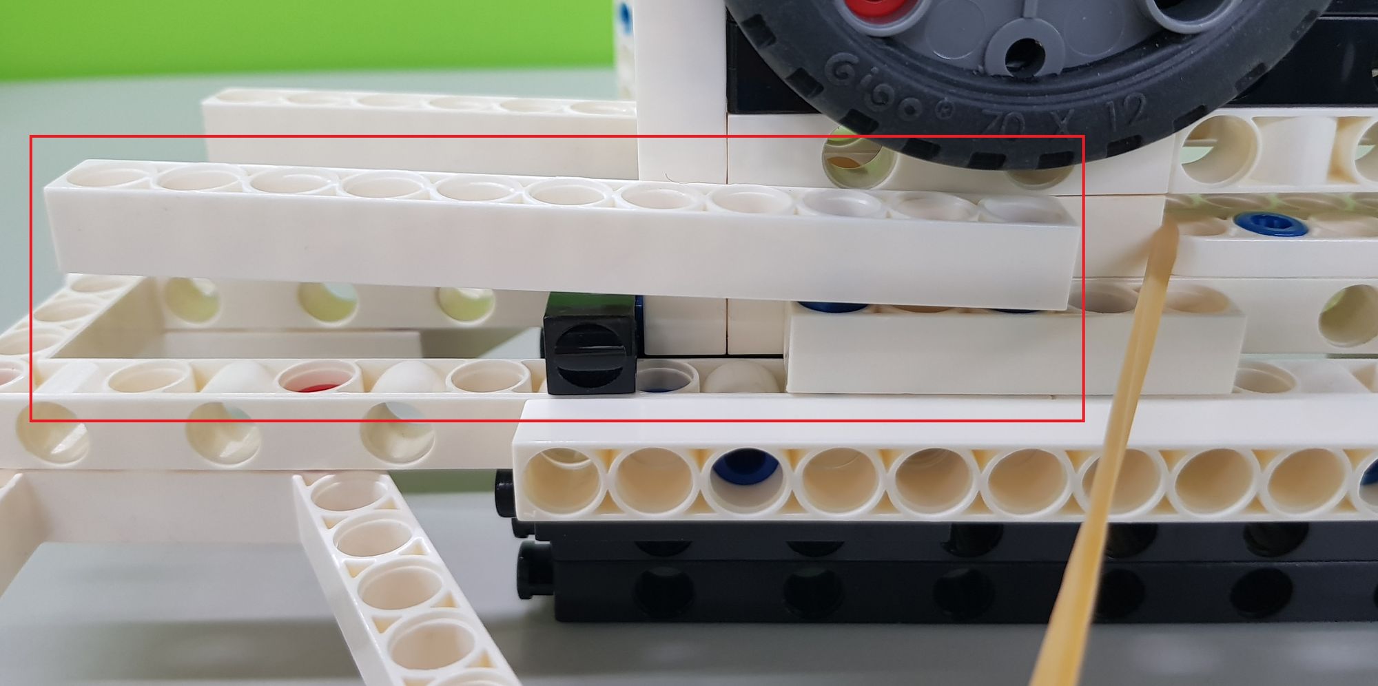
If your flight groove cannot enter the track smoothly due to lifting during operation, you can try to use C-RACING TIRE and C-LONG PEG to make a counterweight (Figure 43), and fix them in front of the flight groove (Figure 44) , or pull the C-11 HOLE ROD of the track slightly upwards to increase the width of the track (Figure 45).

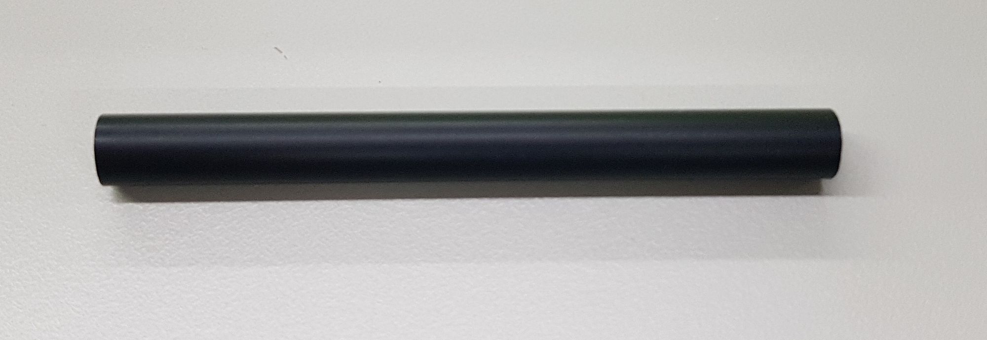
After confirming that it can be fired, we then choose the bullet. The bullet we use here is C-OD8x80mm TUBE (7337-W16-A1D) (Figure 46). If you don’t have an C-OD8x80mm TUBE, you can also use the thin straws on the market, just trim the length to 8 cm.
The next step is to load the bullet. We can put the C-OD8x80mm TUBE or straws into the flight groove in sequence after pulling out the bullet holder, and make sure that each C-OD8x80mm TUBE is horizontal. Then we insert the bullet holder (Video 3).
The last thing is to find an empty field, and try to fire all your bullets (Video 4)!
◆Conclusion
In the Zhuge Crossbow model, we realize that the wisdom of ancient civilizations can serve as the foundation of our own. By studying their experiences, thoughts, and creations, we can acquire valuable scientific knowledge. Moreover, many inventions from ancient times are still prevalent in our modern society. Just think about it: what other modern technologies might have originated from ancient inventions?
That's all for today. If you enjoyed this article, please remember to share it. See you next time! Goodbye!
◆Scientific Principles
The Zhuge Crossbow relies on the scientific principles of linkage and elastic force. The linkage mechanism enables the flight groove to move back and forth, creating a burst effect. The rubber band's elastic force allows it to store energy. When we pull the linkage back, the thick rubber band deforms as it stores the pulling force, a phenomenon known as "deformation". Once the thick rubber band is engaged with the launching bump, it releases the stored energy, launching the C-OD8x80mm TUBE (Video 5).
◆Curriculum(NGSS):
K-2-ETS1-1 Engineering Design
K-PS2-2 Motion and Stability: Forces and Interactions
2-PS1-1 Matter and Its Interactions
#Gigo #Gigo Lab #Learning Lab #Fun Lab
◆References:
 Contributors to Wikimedia projects
 Contributors to Wikimedia projects
 Contributors to Wikimedia projects
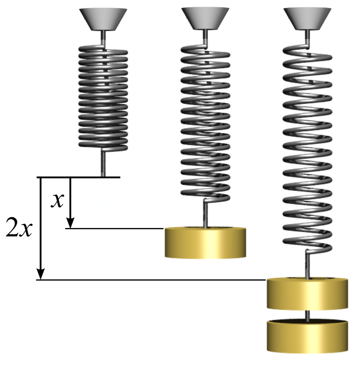 Contributors to Wikimedia projects
.jpg)
Please sign in to vote.