Science in daily life: EP16 –Bionic Bird

Hello, everyone! I’m Teacher Raccoon. Do you remember the bionic beast powered by gravity from Science in Daily Life EP13? Just place it on a slope, and it walks down step by step!
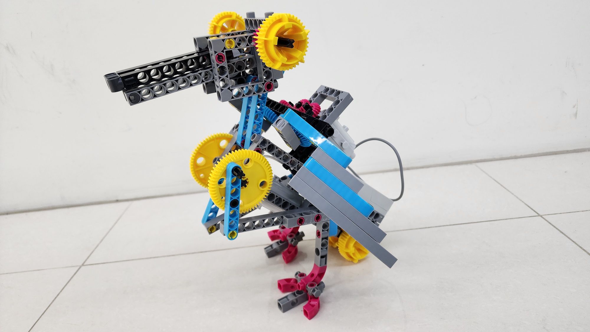
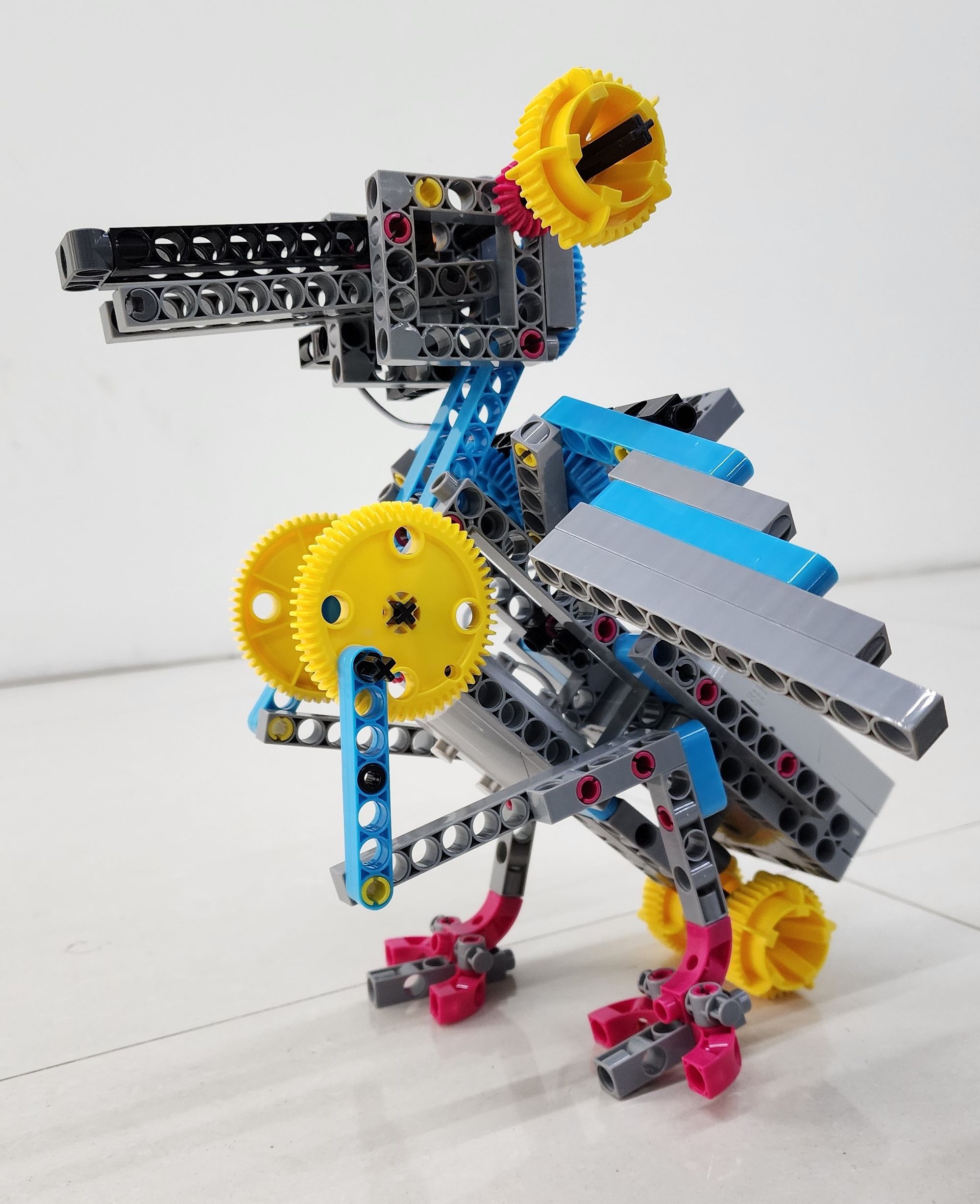
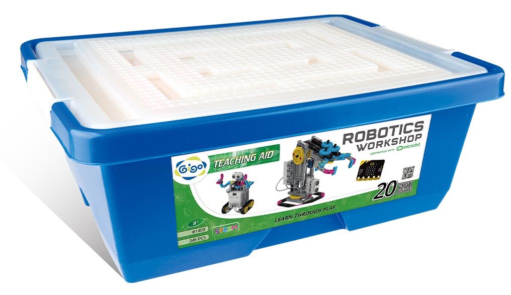
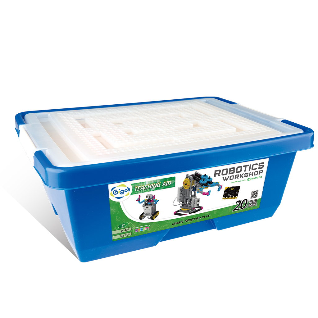
Today, I’ll show you how to use the components from the #1409 ROBOTICS WORKSHOP COMPATIBLE WITH micro:bit to build a bionic bird. With programming, you can make it move, flap its wings, and even open and close its beak! Let’s get started!
Let Teacher Raccoon guide you through the process step by step!
◆ Assembly Steps
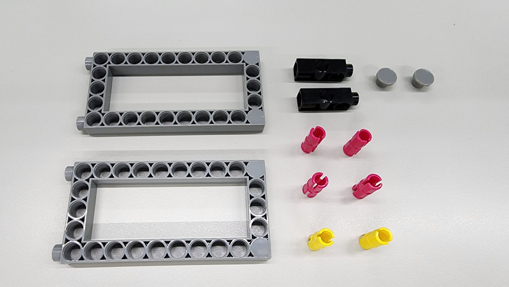
The first step is to build the body of the bionic bird. You'll need the following components:
- C-5×10 FRAME
- C-3 HOLE DUAL ROD
- C-STATIC AXLE CONNECTOR
- C-SHORT BUTTON FIXER
- C-20mm AXLE CONNECTOR (Figure 1)
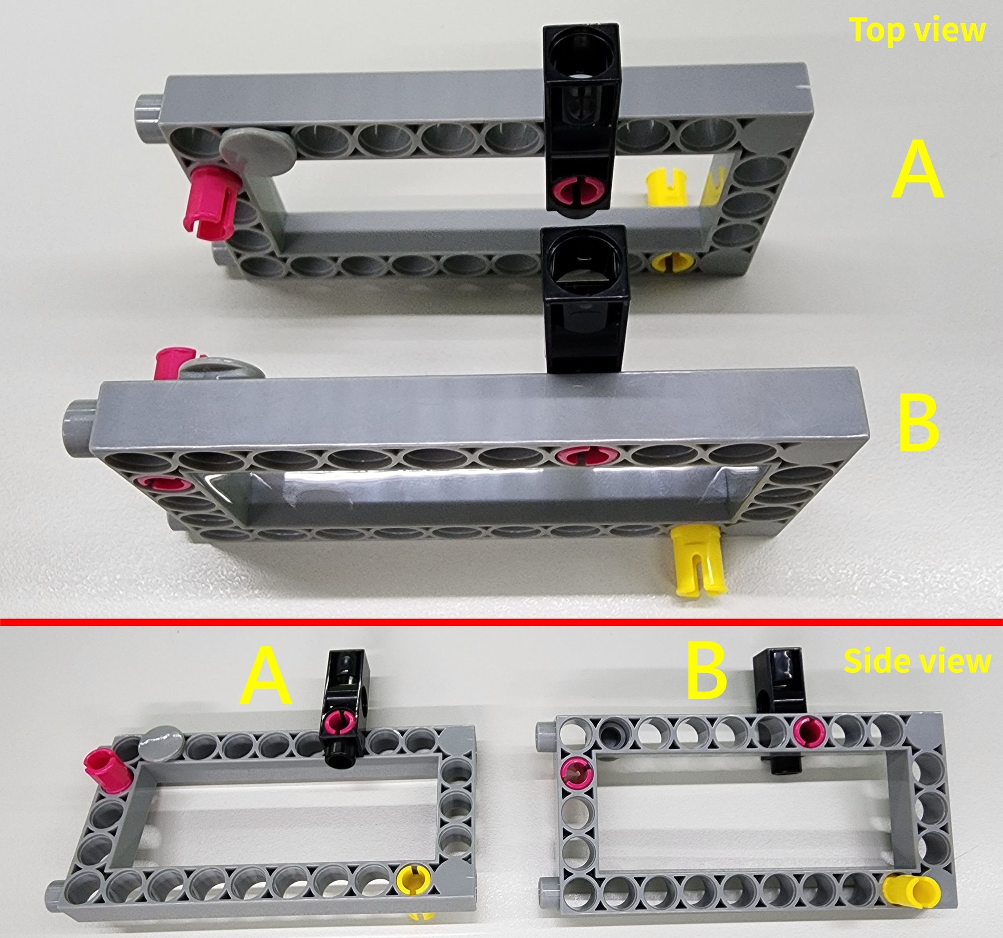
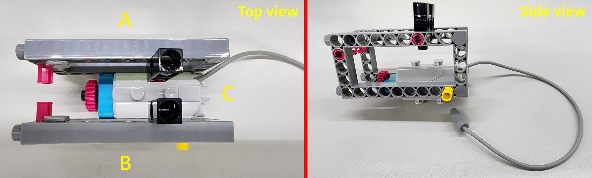
Follow the diagram to assemble these parts onto the C-5×10 FRAME, forming Parts A and B (Figure 2).
Step 2: Installing the Motor
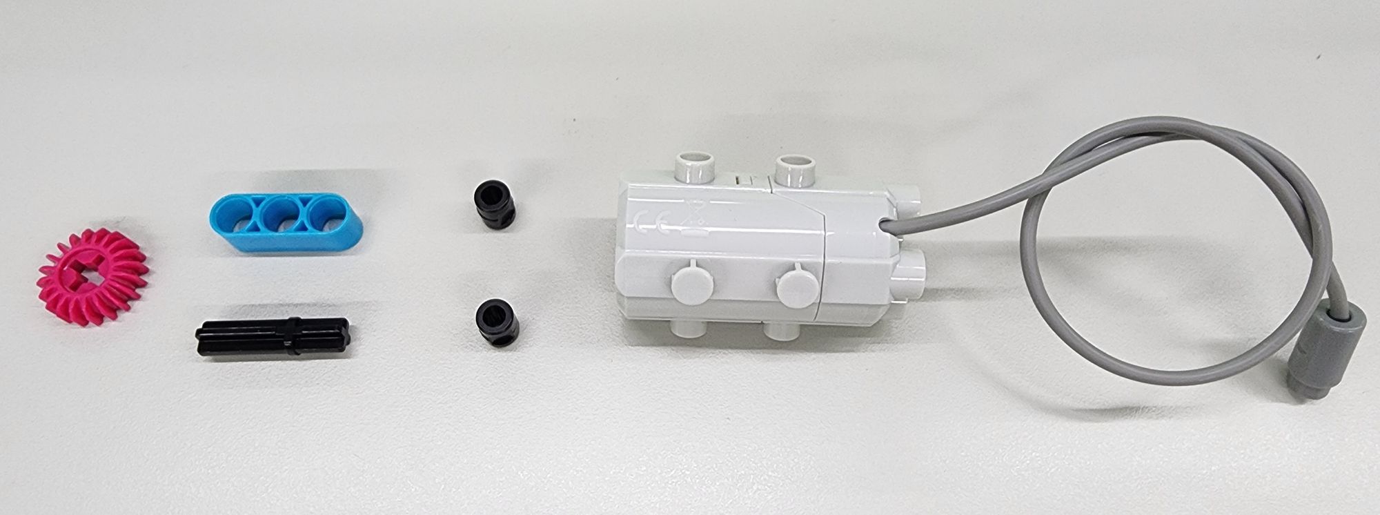
Next, install the motor that drives the feet. You’ll need the following components (Figure 3):
- C-50X PLANETARY GEARBOX
- C-20T GEAR
- C-3 HOLE ROUND ROD
- C-30mm AXLE Ⅱ
- B-SHORT PEG
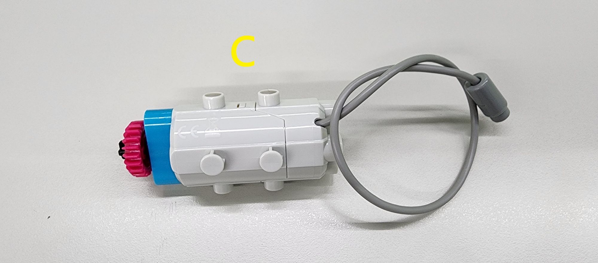
Follow the diagram to assemble these parts into Part C (Figure 4).
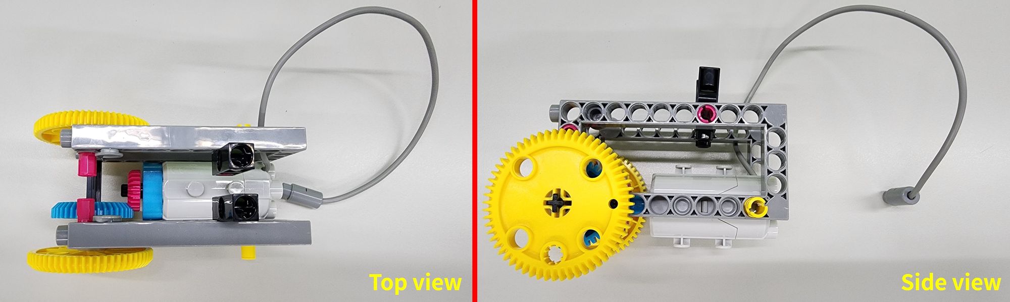
Next, position Part C between Parts A and B, as shown in the diagram, to complete the installation of the C-50X PLANETARY GEARBOX and the bird's body (Figure 5).
Step 3: Extending the Motor’s Power with Gears
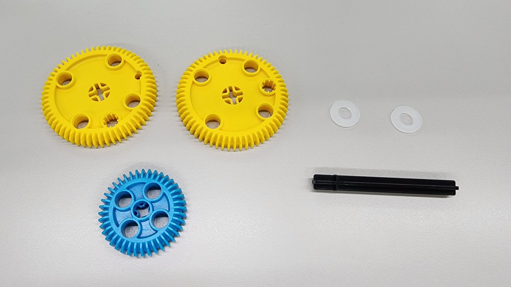
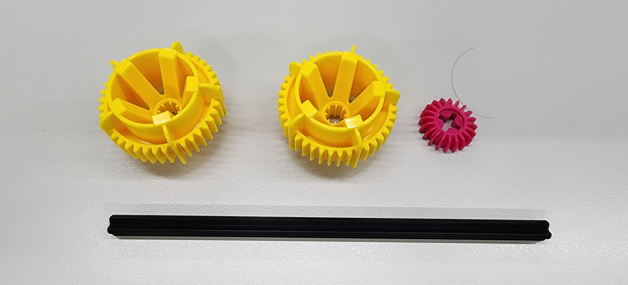
Now, use a gear set to transfer and extend the motor's power. You'll need the following components (Figure 6):
- C-60T GEAR
- C-40T GEAR WITH HOLE
- O-PLASTIC WASHER M8*16
- C-70mm AXLE Ⅱ
Attach these parts to the body as shown in the diagram (Figure 7).
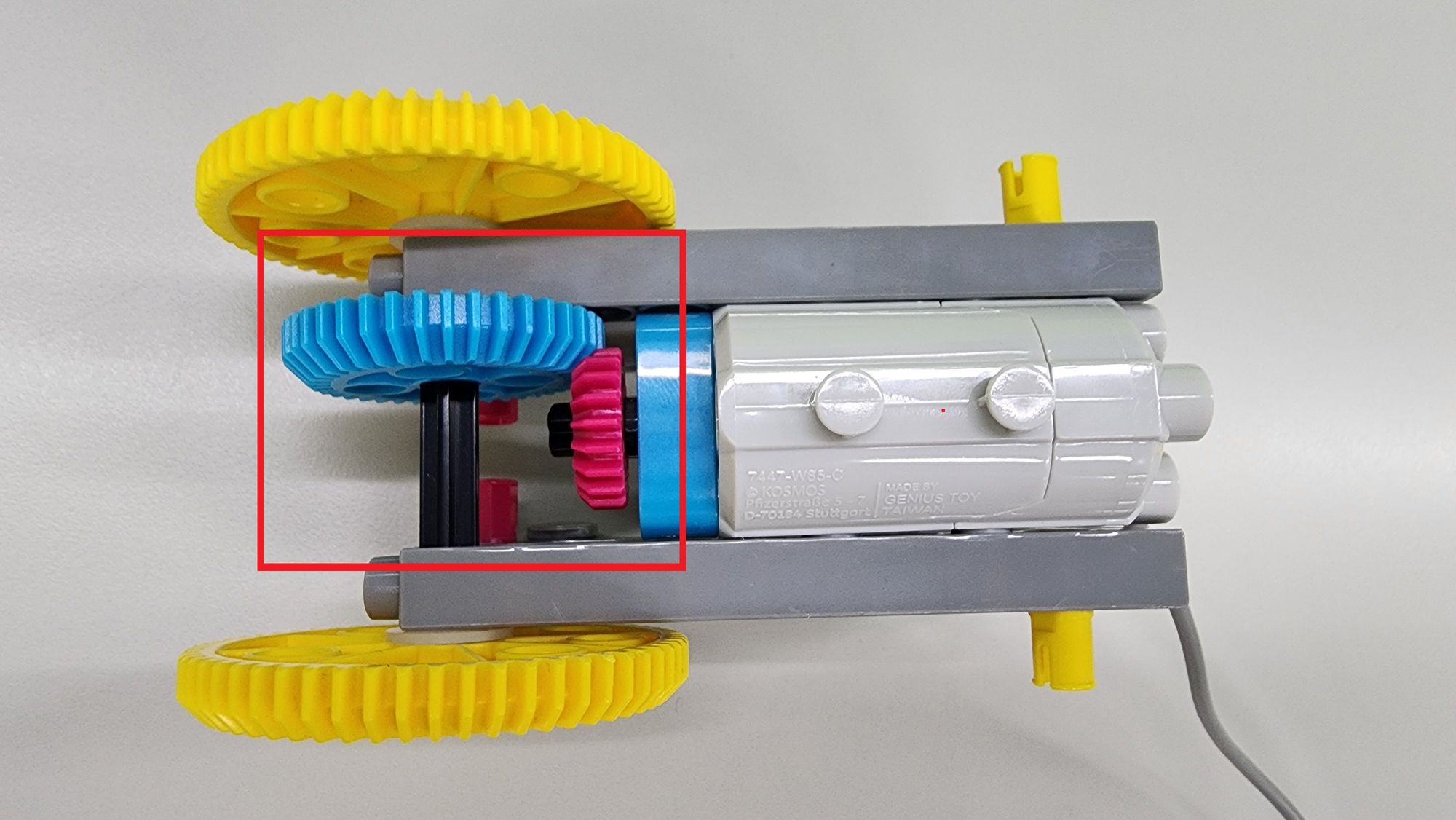
Once the gear set is installed, ensure that the C-40T GEAR WITH HOLE properly meshes with the C-20T GEAR on the C-50X PLANETARY GEARBOX (Figure 8). This allows the motor’s power to be effectively transmitted to the C-60T GEAR.
Step 4: Assembling the Tail Feathers
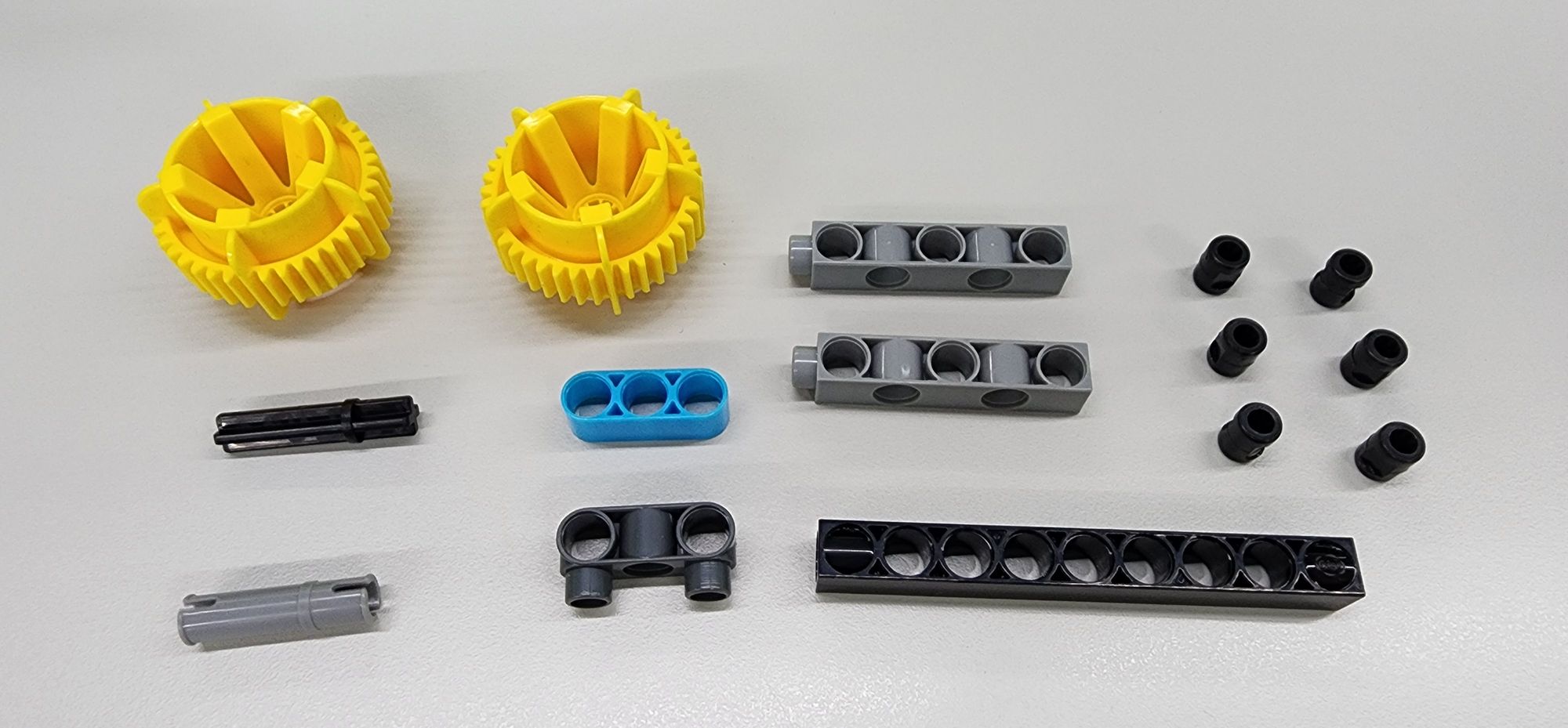
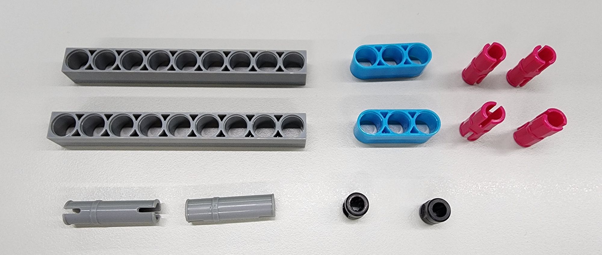
Next, we’ll create the tail feathers to support the body. You'll need the following components (Figure 9):
- C-40T WHEEL FRAME
- C-35mm AXLE Ⅱ
- C-30mm AXLE CONNECTOR
- C-3 HOLE ROUND ROD
- C-3 HOLE DUAL ROUND ROD WITH PEGS
- C-5 HOLE DUAL ROD BOTTOM CLOSED
- C-9 HOLE ROD FRONT CLOSED
- B-SHORT PEG
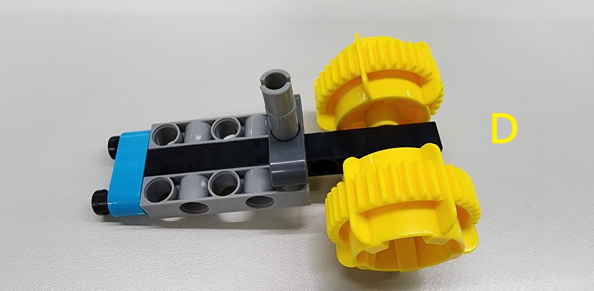
Assemble these parts according to the diagram to complete Part D (Figure 10).
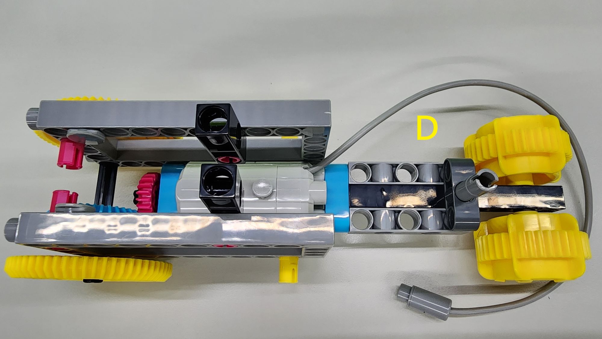
Next, attach Part D to the rear of the C-50X PLANETARY GEARBOX, completing the assembly of the tail feathers and body (Figure 11).
Step 5: Attaching the micro:bit C-SMART CONTROLLER
Now, we’ll secure the micro:bit C-SMART CONTROLLER to the tail feathers and body. You'll need the following components (Figure 12):
- C-9 HOLE ROD
- C-30mm AXLE CONNECTOR
- C-3 HOLE ROUND ROD
- C-STATIC AXLE CONNECTOR
- B-SHORT PEG
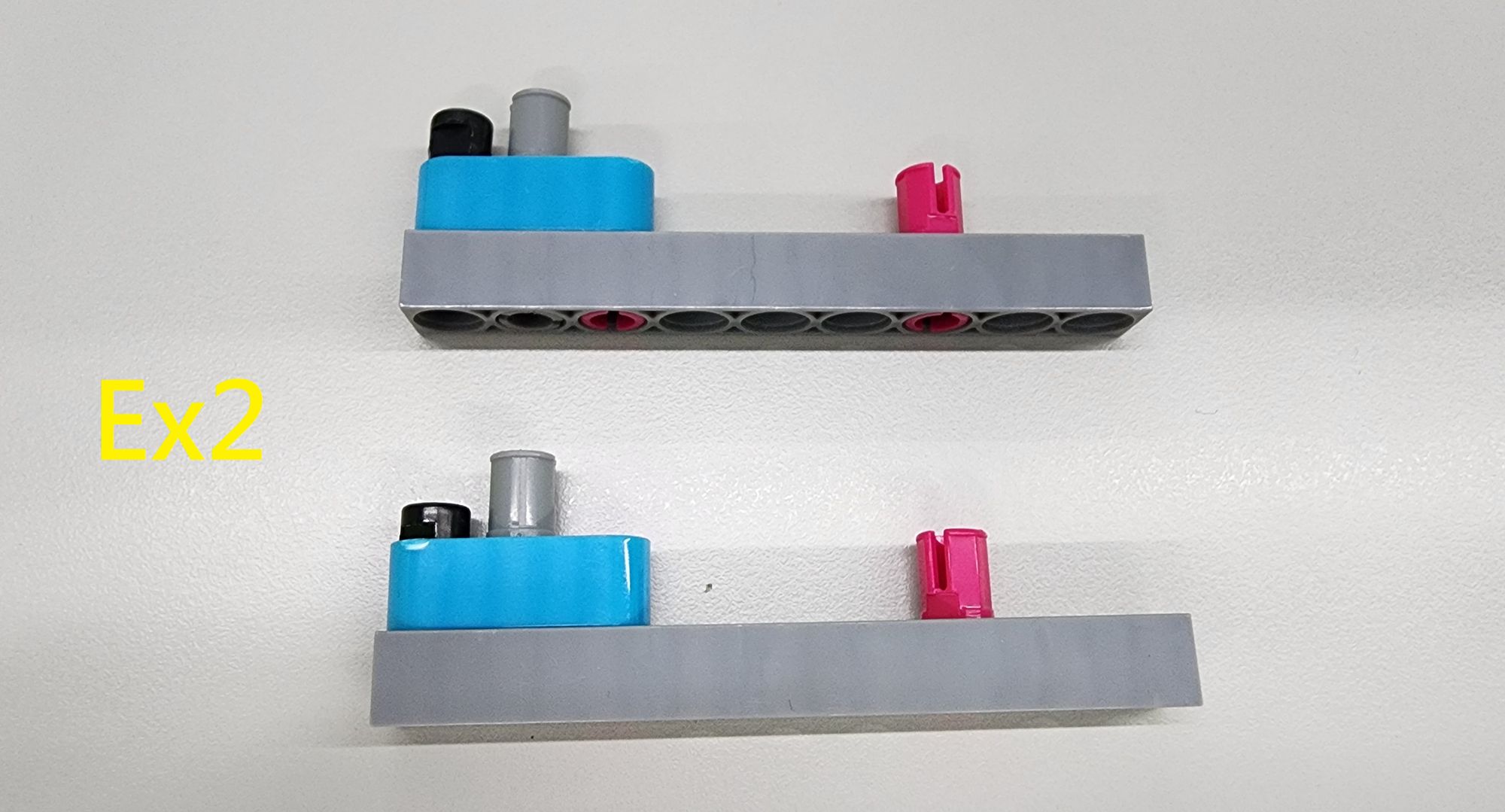
Assemble these parts according to the diagram to create two Parts E (Figure 13).
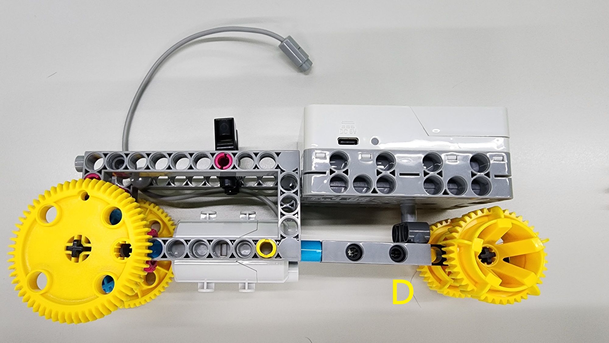
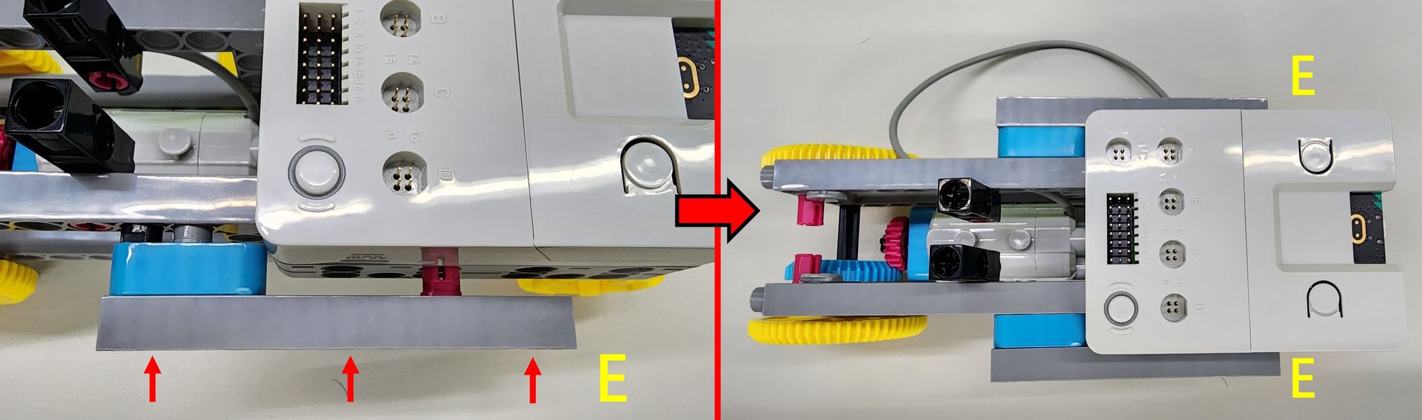
Next, connect the C-SMART CONTROLLER to the C-30mm AXLE CONNECTORof Part D as shown in the diagram (Figure 14). Use the two Part Eparts to reinforce the connection, completing the attachment of the C-SMART CONTROLLER to the tail feathers and body (Figure 15).
Step 6: Assembling the Legs
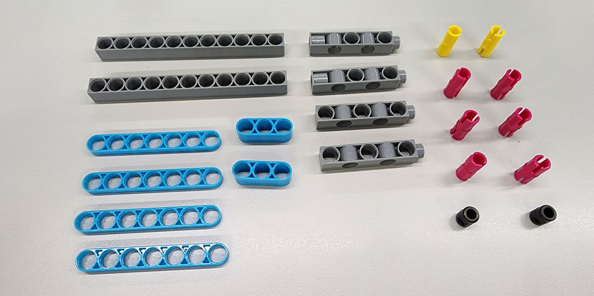
- Now, let’s build the legs of the bionic bird. You’ll need the following components (Figure 16):
- C-11 HOLE ROD
- C-7 HOLE WIDE PROLATE ROD
- C-3 HOLE ROUND ROD
- C-5 HOLE DUAL ROD II
- C-5 HOLE DUAL ROD BOTTOM CLOSED
- C-20mm AXLE CONNECTOR
- C-STATIC AXLE CONNECTOR
- B-SHORT PEG
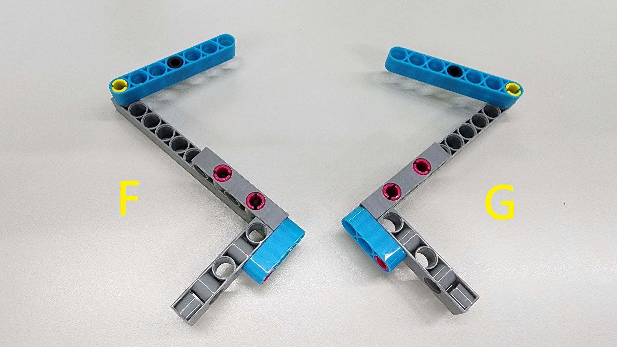
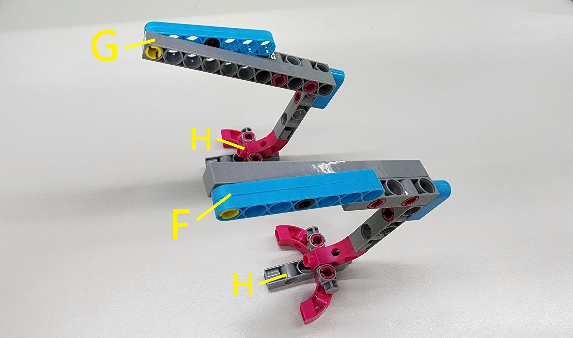
Assemble these parts according to the diagram to complete Parts F and G (Figure 17).
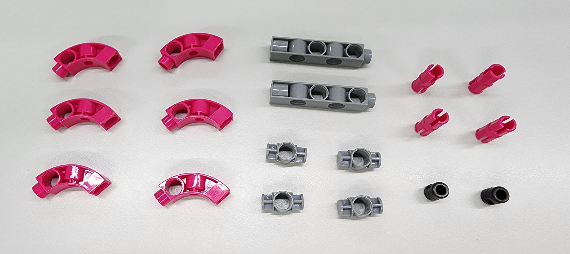
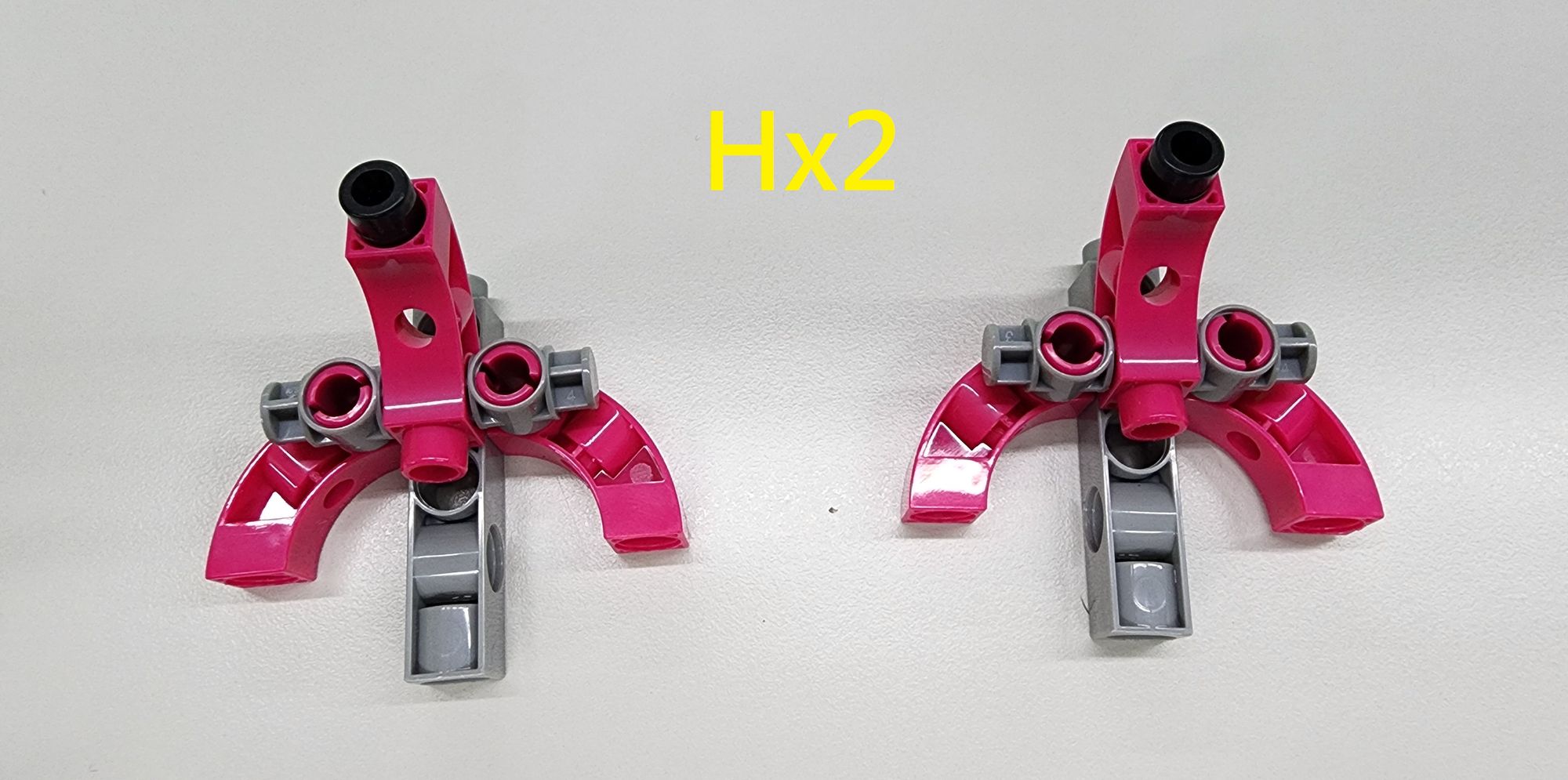
Next, we will assemble the structure of the bird claw using a C-BENDED ROD, a C-5 HOLE DUAL ROD II, C-1 HOLE CONNECTOR, C-STATIC AXLE CONNECTOR, and B-SHORT PEG (Figure 18). Follow the diagram to properly combine the components and complete the construction of the two H Parts (Figure 19).
Next, attach the two H Parts beneath Parts F and G, respectively, following the diagram. This completes the left foot (Part F) and right foot (Part G) of the bionic bird (Figure 20).
Step 7: Attach the Legs to the Bionic Bird's Body
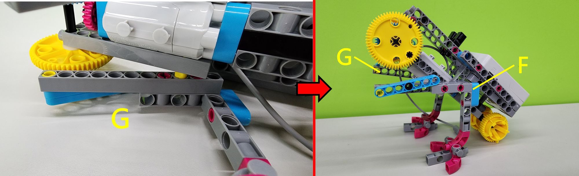
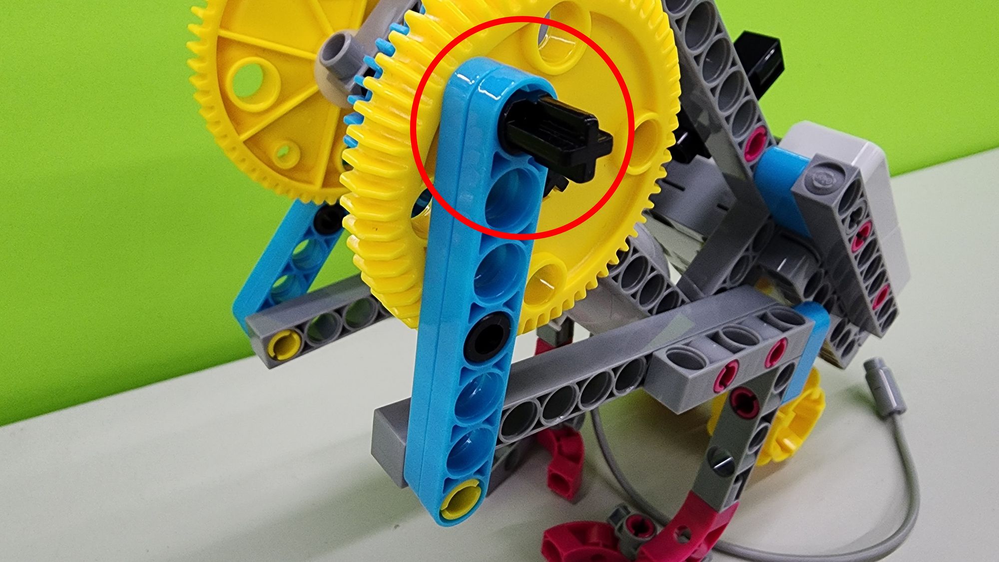
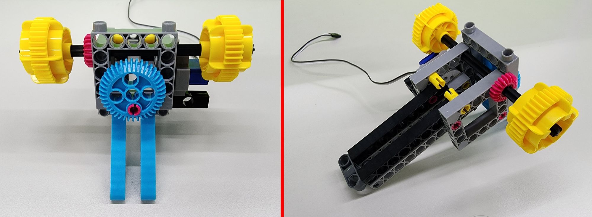
First, secure Parts F and G onto the C-20mm AXLE CONNECTOR as shown (Figure 21). Ensure the C-20mm AXLE CONNECTOR is positioned correctly; otherwise, the bionic bird may not move smoothly.
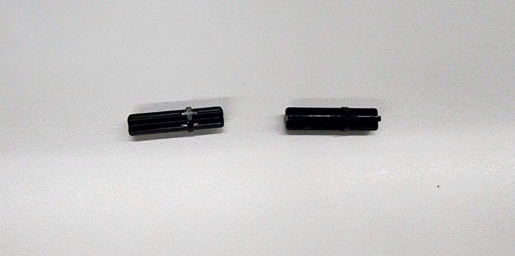
Next, we will use two C-30mm AXLE Ⅱ (Figure 22) to connect the C-60T GEAR on the body to the linkage on the legs. Following the diagram, insert the C-30mm AXLE Ⅱ through the linkage on the legs and into the holes of the C-60T GEAR (Figure 23).
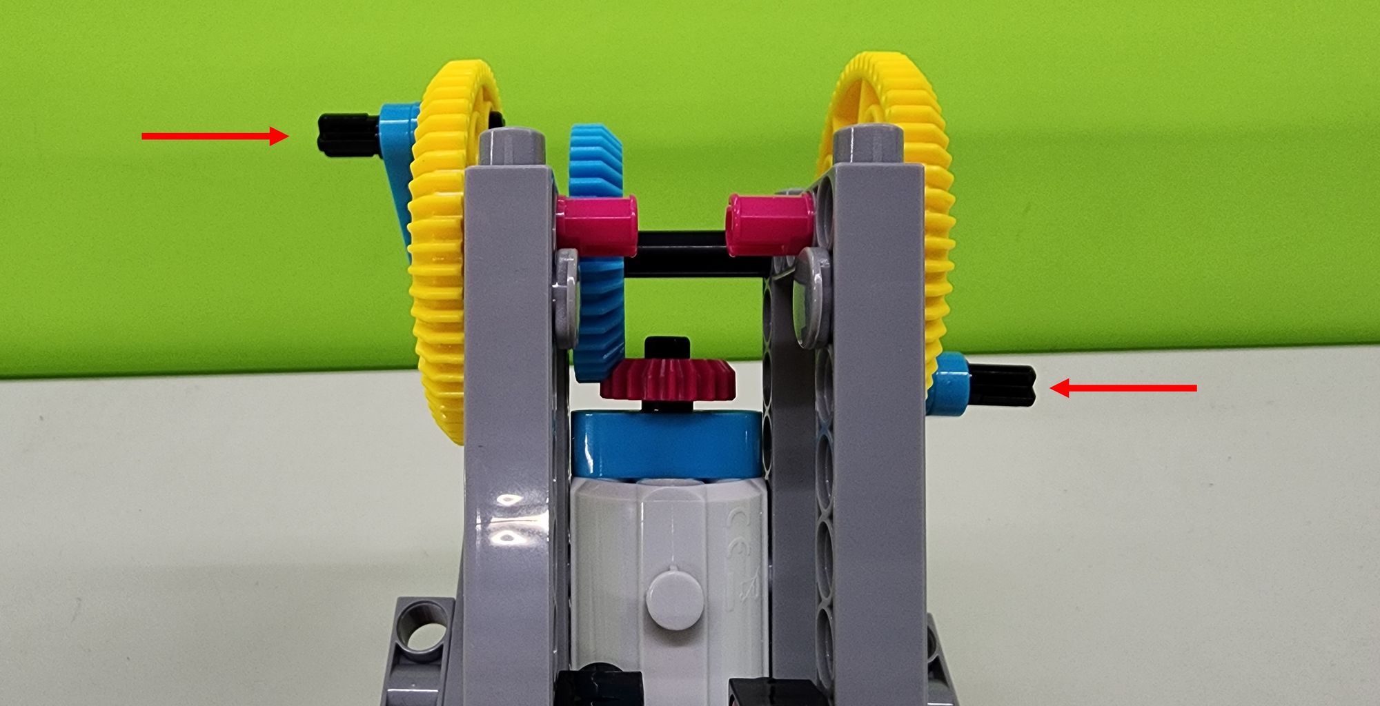
After installing the double-leg linkage, check the positioning of both C-30mm AXLE Ⅱ. For optimal movement, one axle should be positioned higher and the other lower (Figure 24). If the assembly is incorrect, remove the C-60T GEAR, adjust the positioning, and then reinstall the linkage and C-30mm AXLE Ⅱ after verifying their alignment.
Step 8: Assembling the Wings of the Bionic Bird
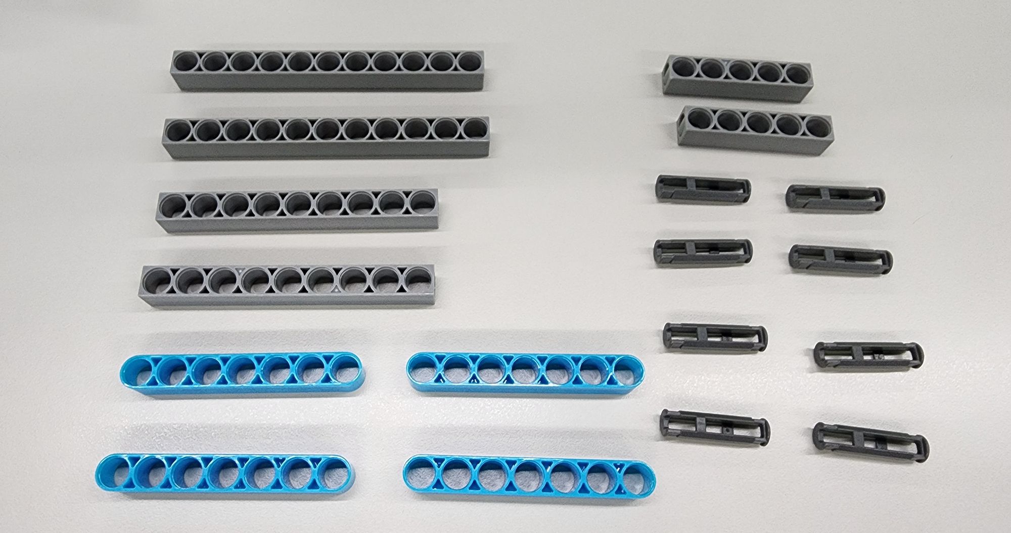
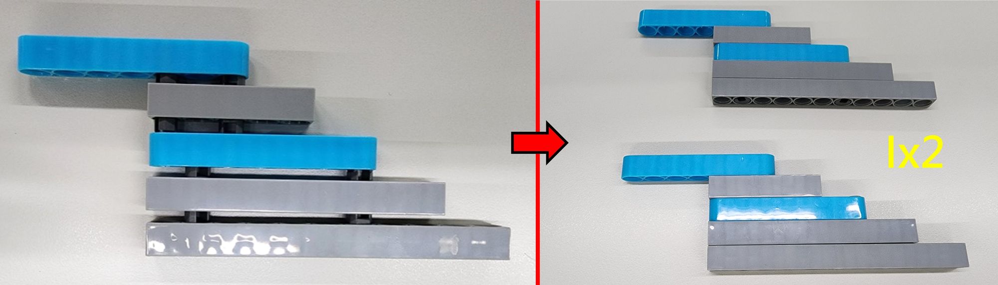
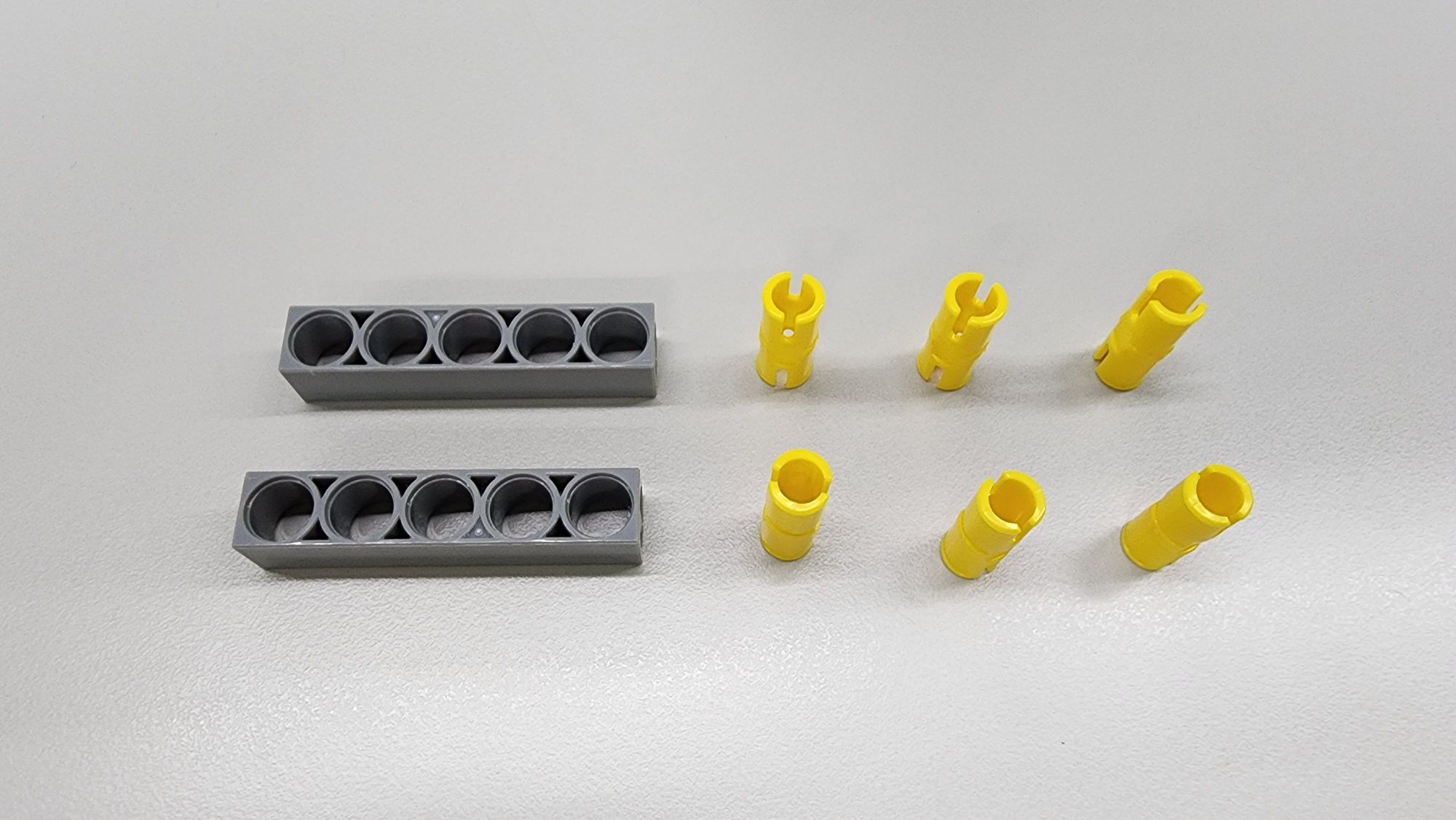
In this step, we will construct the wings of the bionic bird using C-11 HOLE ROD, C-9 HOLE ROD, C-7 HOLE ROUND ROD, C-5 HOLE ROD II, and C-30mm STATIC CONNECTOR TUBE (Figure 25). Follow the diagram to assemble the components and complete the two I Parts (Figure 26).
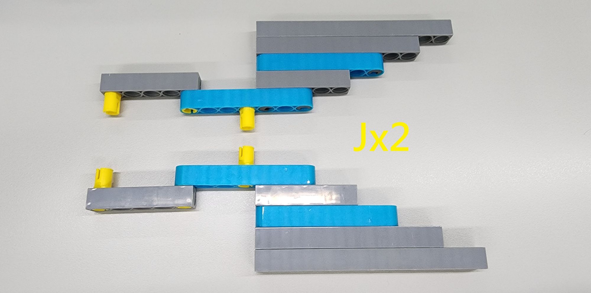
Next, to attach the linkage to the wings, use the C-5 HOLE ROD II and the C-20mm AXLE CONNECTOR (Figure 27). Follow the diagram to assemble these components onto Part I, completing the two J Parts (Figure 28).
Step 9: Assembling the Wing Base
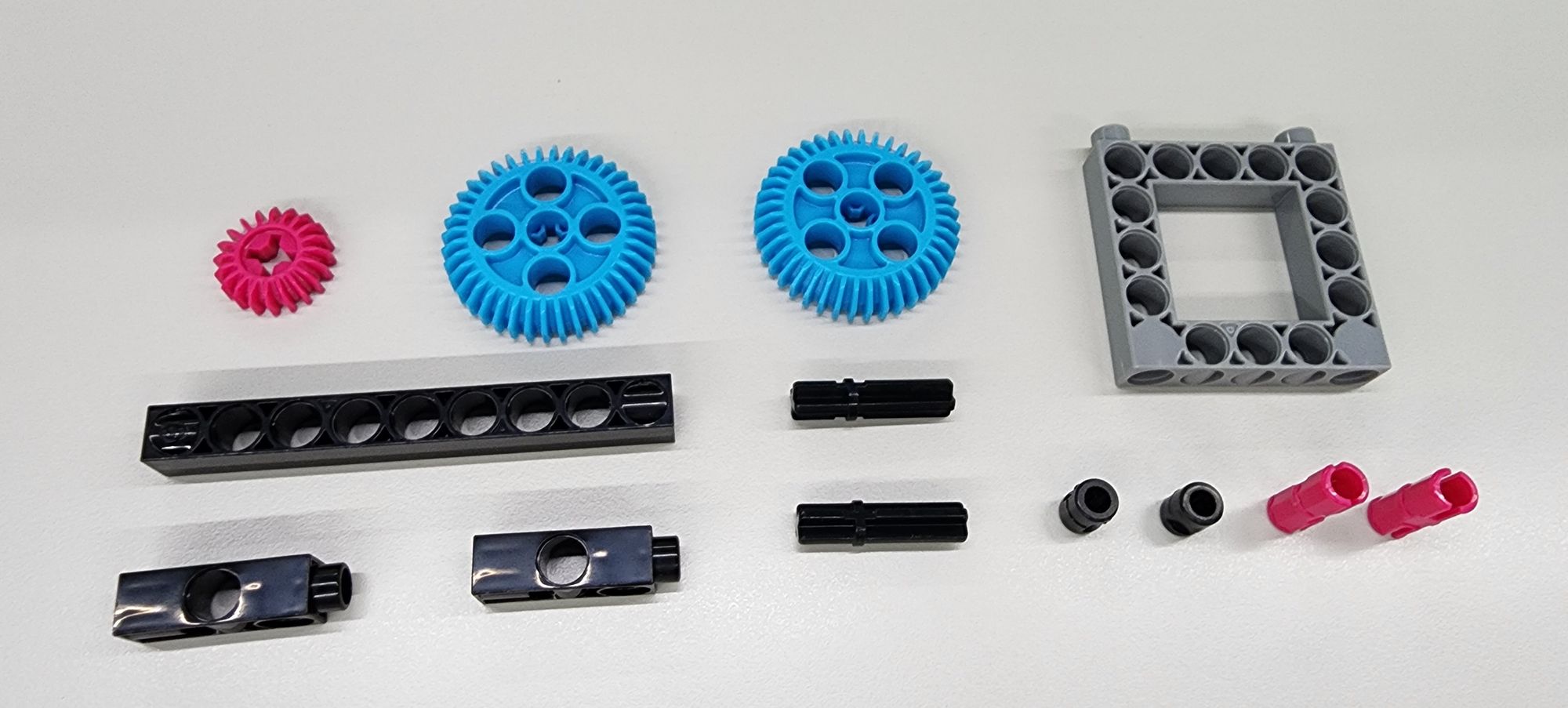
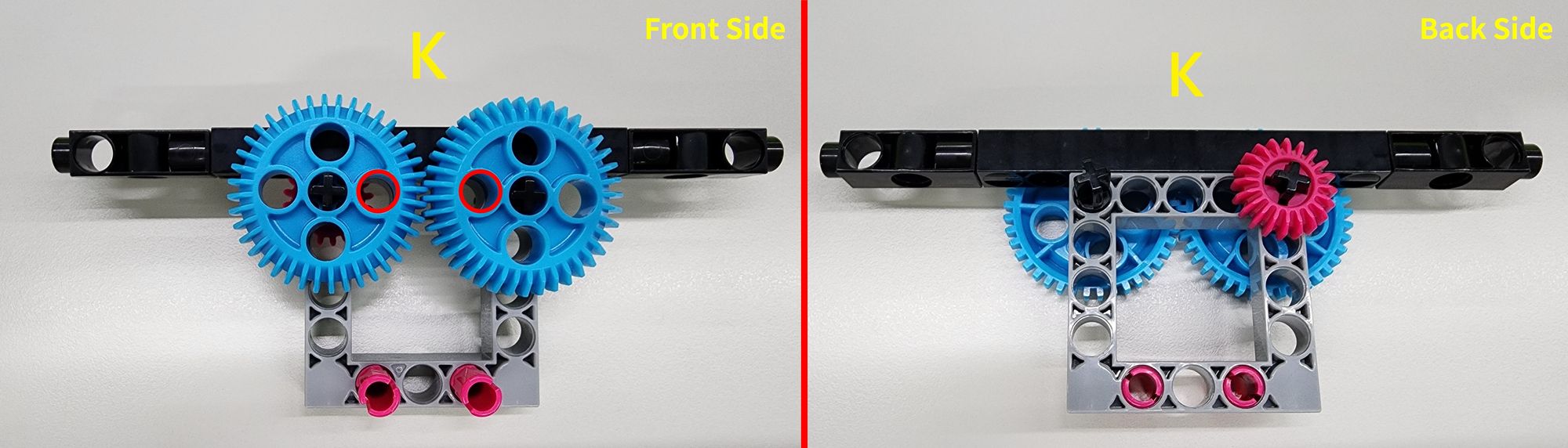
In this step, we will construct the wing base using a C-20T GEAR, two C-40T GEAR WITH HOLE, a C-9 HOLE ROD FRONT CLOSED, a C-3 HOLE DUAL ROD, a C-30mm AXLE Ⅱ, a C-5×5 FRAME II, a C-STATIC AXLE CONNECTOR, and a B-SHORT PEG (Figure 29). Follow the diagram to assemble these components and complete the K Part. During assembly, ensure that the hole positions on both C-40T GEAR WITH HOLE are correctly aligned (Figure 30).
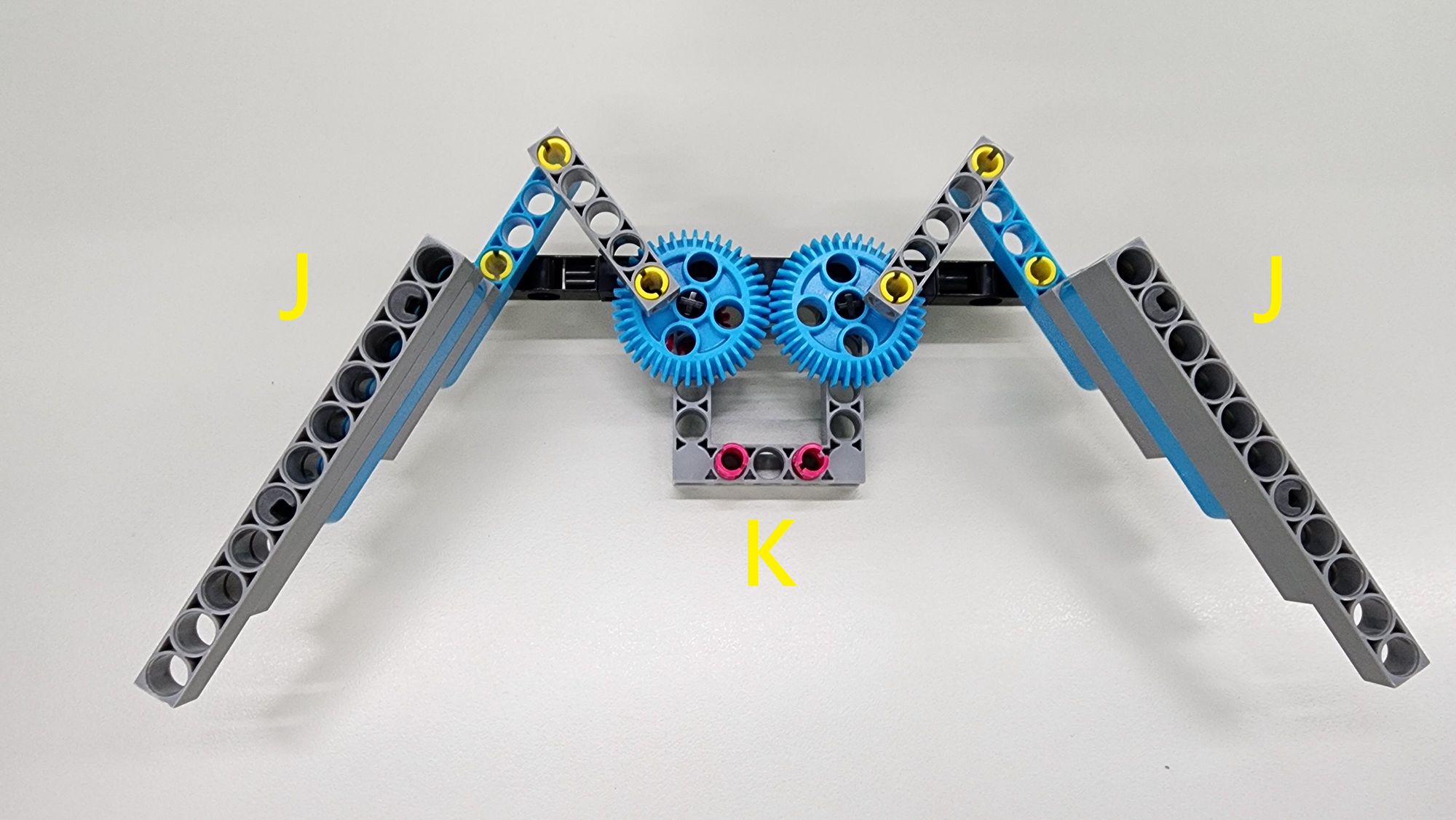
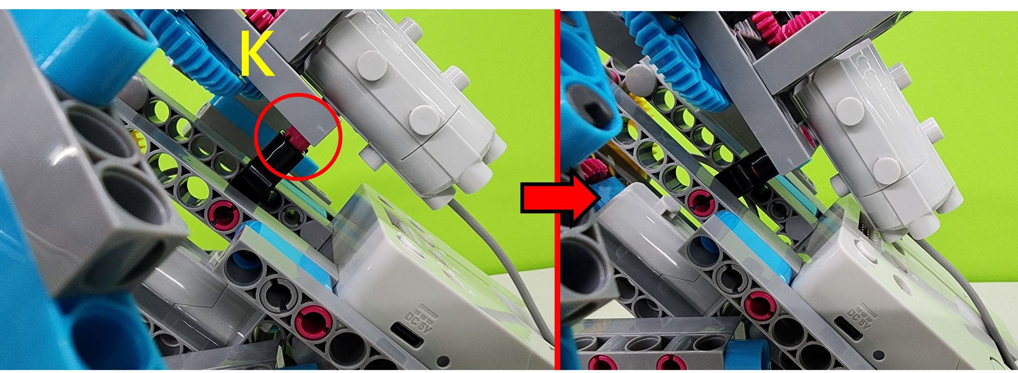
Next, attach the C-20mm AXLE CONNECTOR of Part J to Part K to securely connect the wings to the wing base (Figure 31).
Step 10: Installing the Motor for the Wings
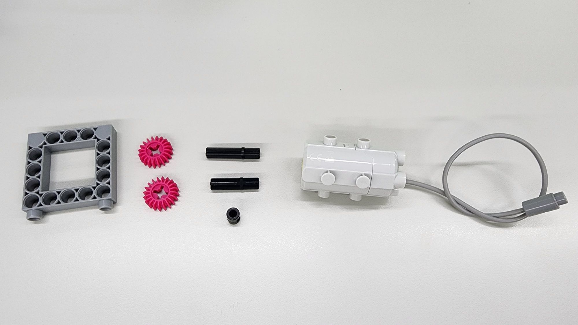
In this step, we will install the motor that drives the wings. The required components include a C-5×5 FRAME II, a C-20T GEAR, a C-35mm AXLE Ⅱ, a C-30mm AXLE Ⅱ, a B-SHORT PEG, and a C-50X PLANETARY GEARBOX (Figure 32).
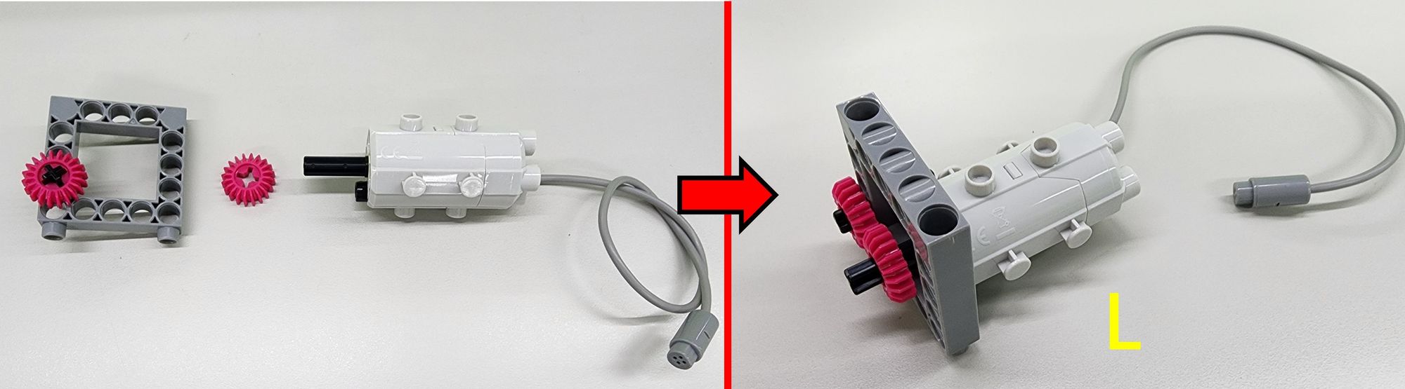
First, attach the B-SHORT PEG and the C-35mm AXLE Ⅱ to the C-50X PLANETARY GEARBOX as shown. Next, place the C-5×5 FRAME II with the C-30mm AXLE Ⅱ and C-20T GEAR onto the assembly. Finally, insert an additional C-20T GEAR onto the C-35mm AXLE Ⅱ to complete the L Part (Figure 33).
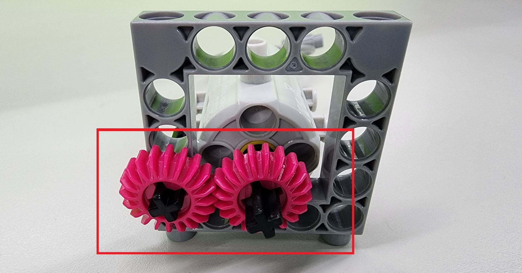
After installing Part L, ensure that the two C-20T GEAR on the C-30mm AXLE Ⅱ and the C-35mm AXLE Ⅱ mesh properly with each other (Figure 34).
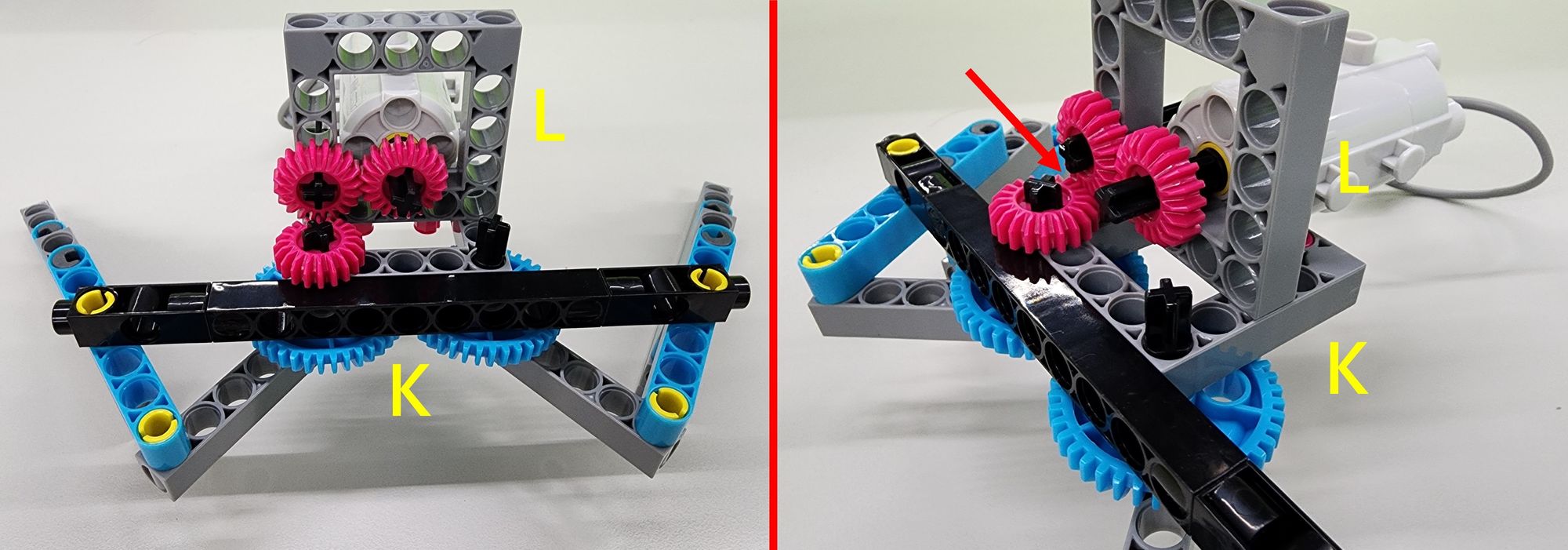
Next, install Part L onto Part K as shown in the diagram. Ensure that the C-20T GEAR on both Part L and Part K mesh properly with each other (Figure 35) to complete the power mechanism for the wings.
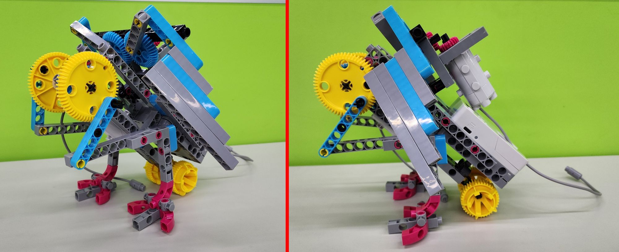
Finally, attach Part K to the top of the body (Figure 36) to securely fix the wing base to the body (Figure 37).
Step 11: Assembling the Head of the Bionic Bird
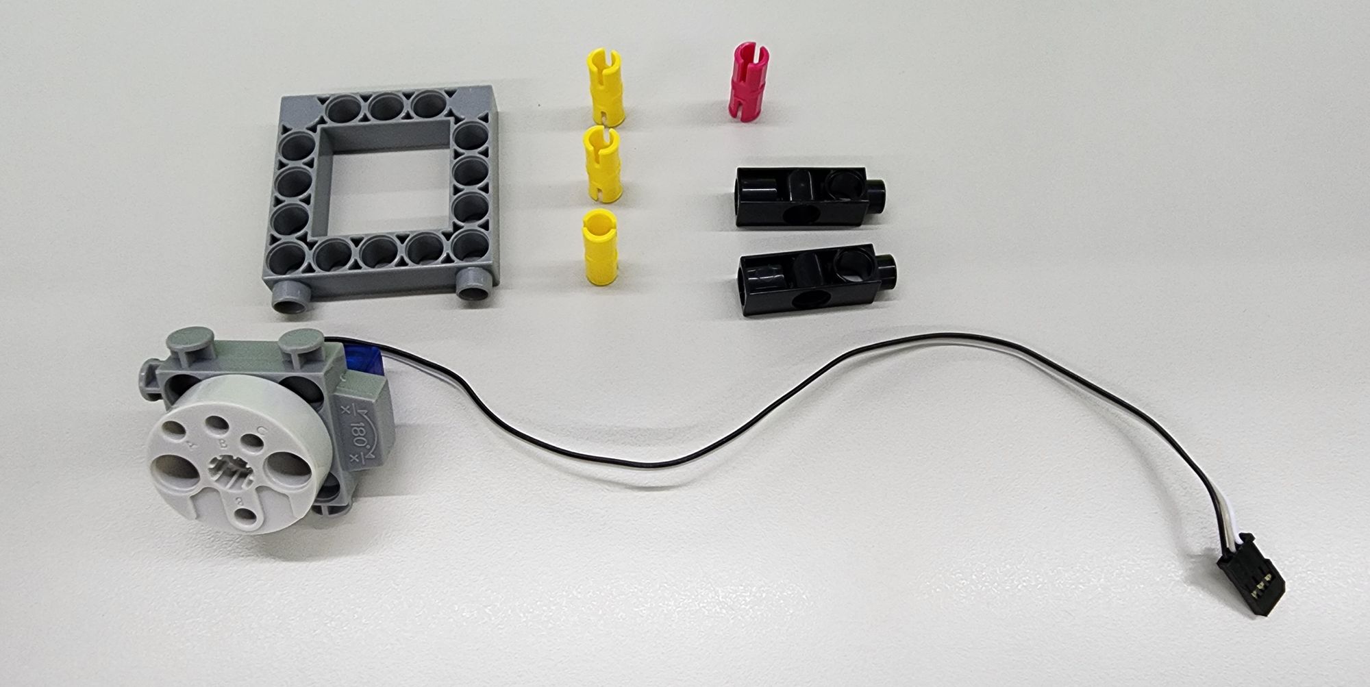
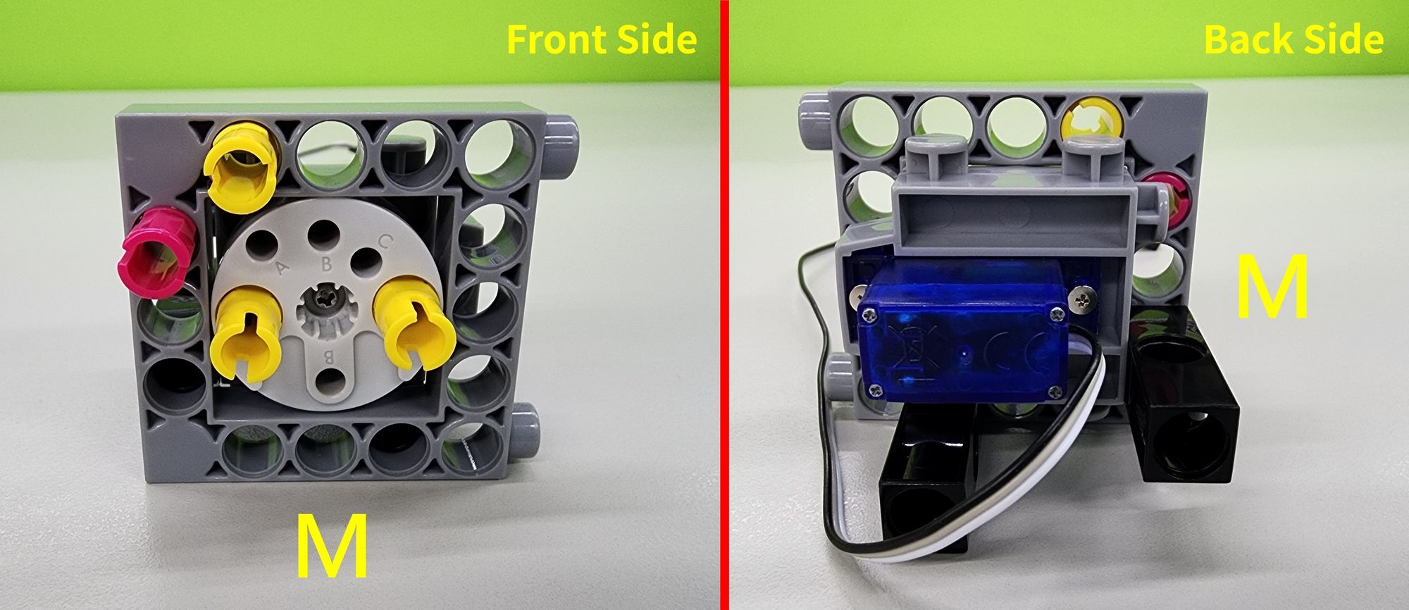
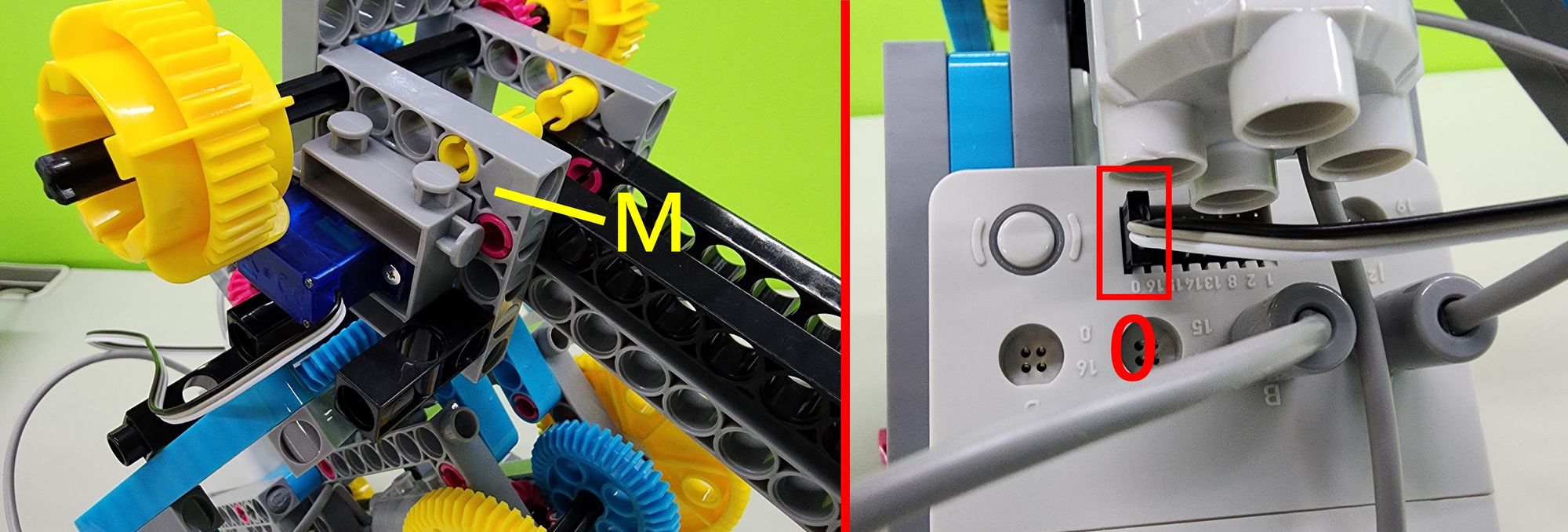
In this step, we will construct the head of the bionic bird using the C-5×5 FRAME II, a C-180° SERVO MOTOR, a C-3 HOLE DUAL ROD, a C-20mm AXLE CONNECTOR, and a C-STATIC AXLE CONNECTOR (Figure 38). Follow the diagram to assemble the components and complete the Part M (Figure 39).
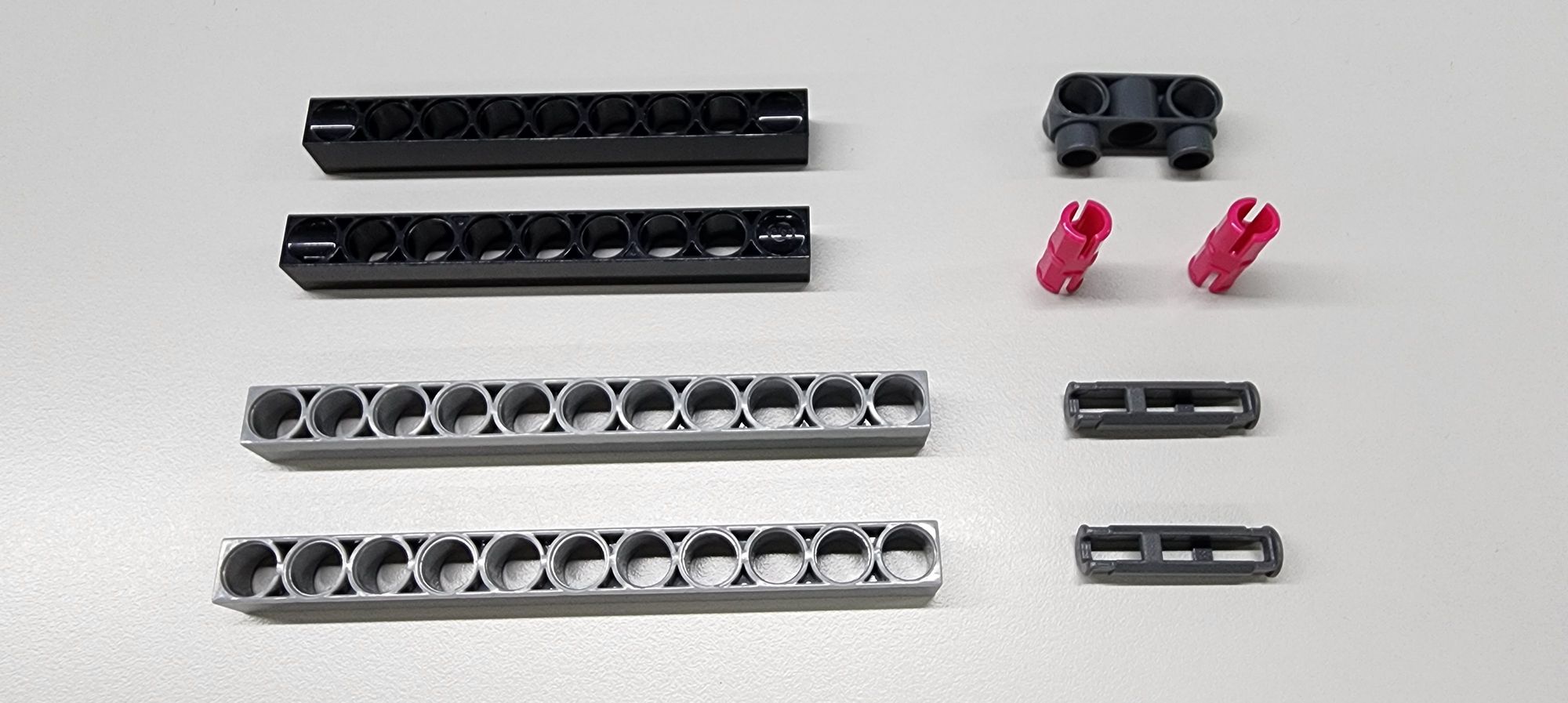
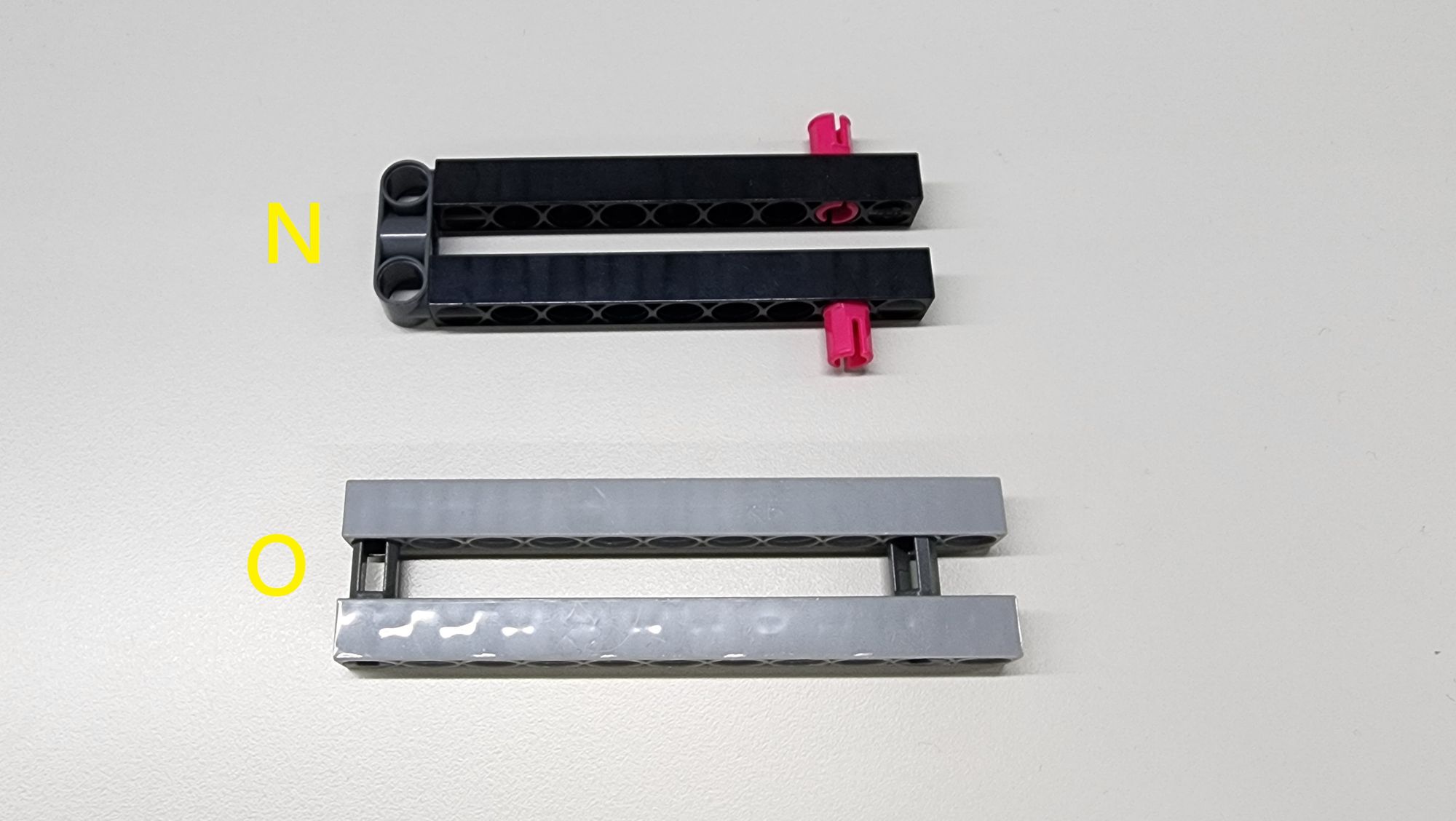
Next, we will assemble the beak of the bionic bird using a C-9 HOLE ROD FRONT CLOSED, a C-11 HOLE ROD, a C-3 HOLE DUAL ROUND ROD WITH PEGS, a C-30mm STATIC CONNECTOR TUBE, and a C-STATIC AXLE CONNECTOR (Figure 40). Follow the diagram to combine the parts and complete the production of Parts N and O (Figure 41).
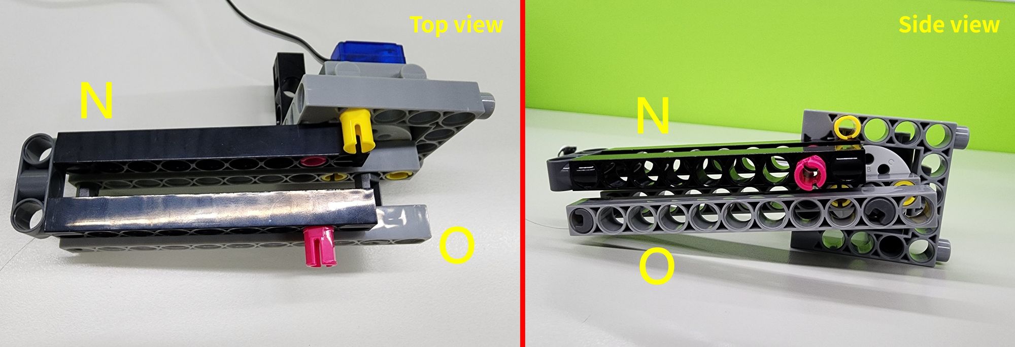
Finally, attach Parts N and O to Part M as shown (Figure 42) to complete the upper (Part N) and lower (Part O) sections of the bird's beak.
Step 12: Assembling the Neck and Reinforcing the Head of the Bionic Bird
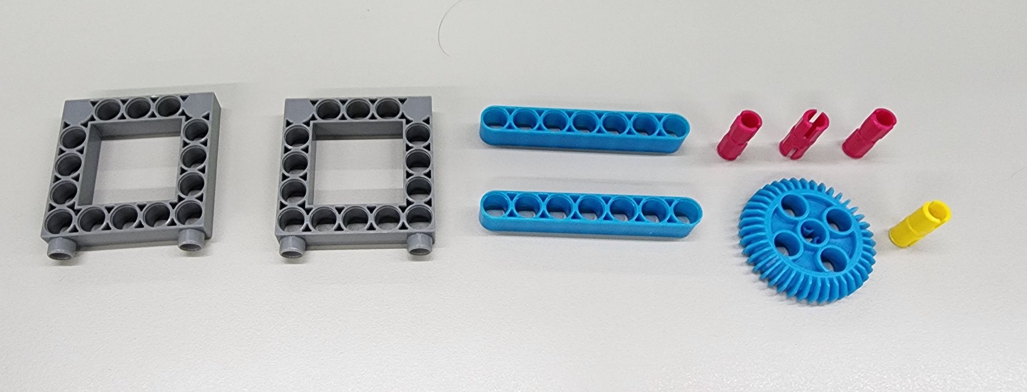
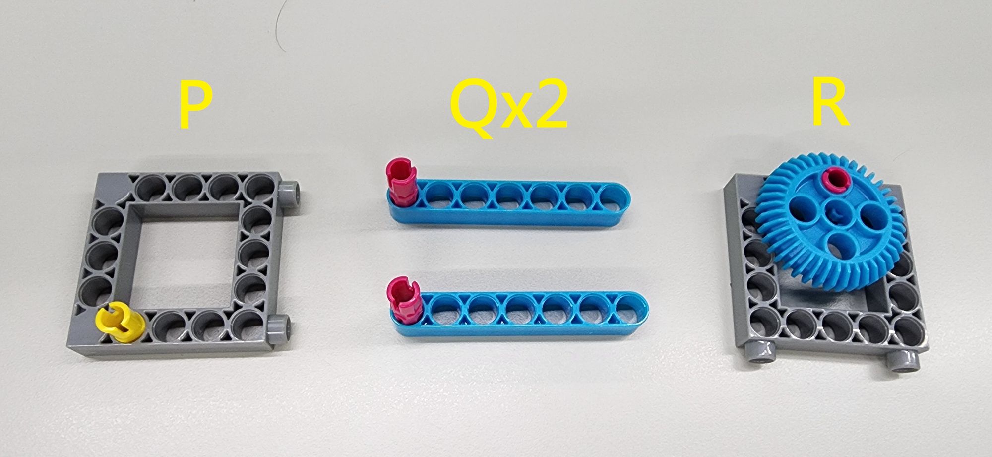
In this step, we will assemble the neck and reinforce the head of the bionic bird using a C-5×5 FRAME II, a C-7 HOLE ROUND ROD, a C-STATIC AXLE CONNECTOR, a C-40T GEAR WITH HOLE, and a C-20mm AXLE CONNECTOR (Figure 43). Follow the diagram to combine the components and complete the production of Part P, two Parts Q, and Part R (Figure 44).
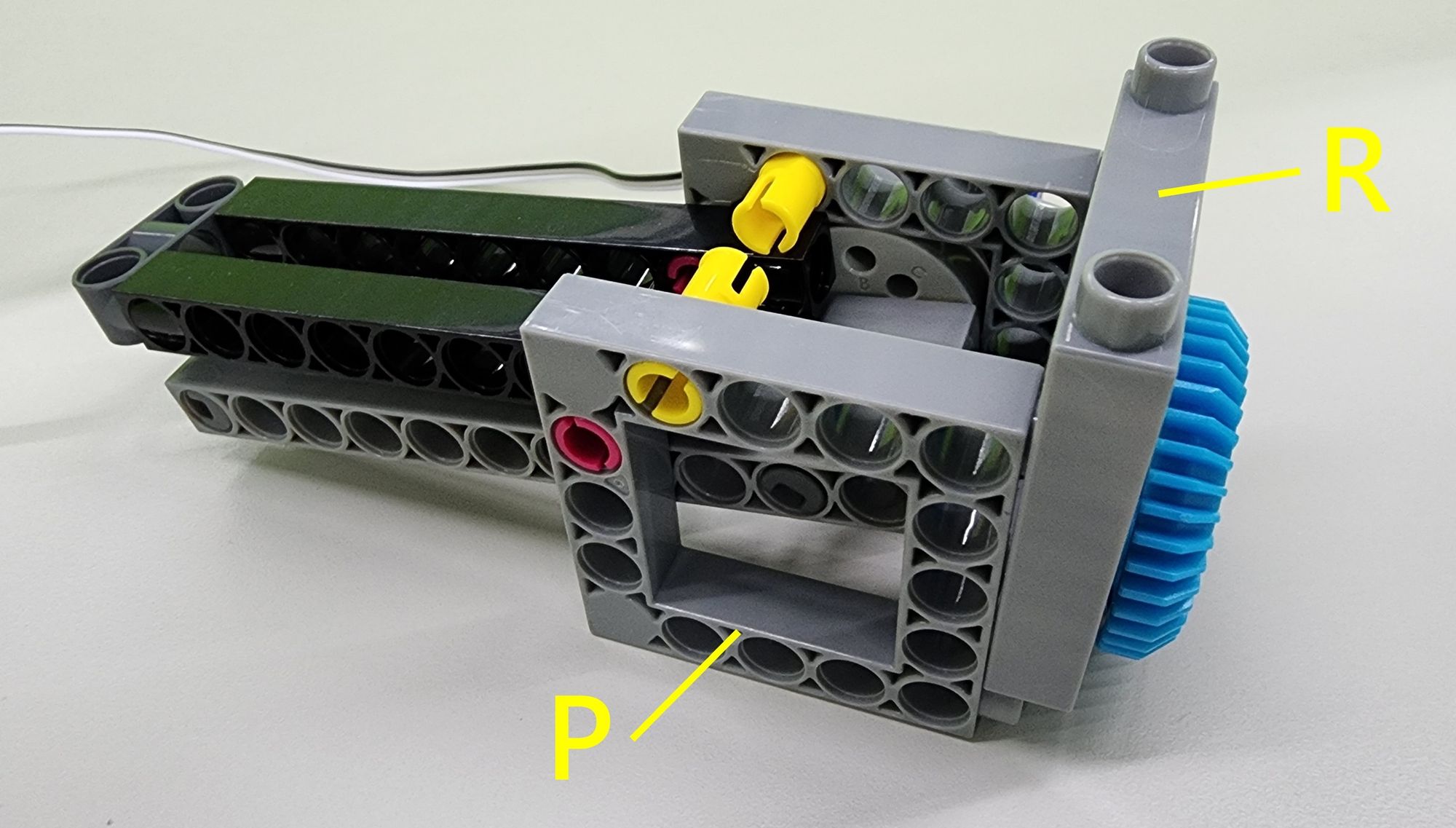
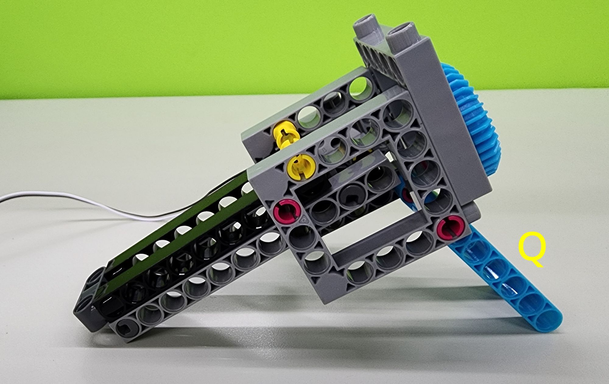
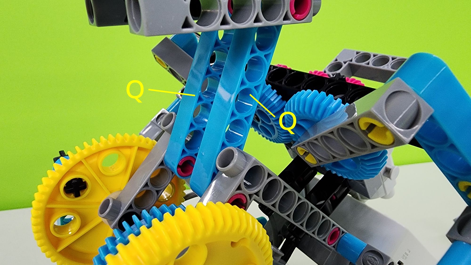
Next, attach Parts P and R to part M as shown (Figure 45) to reinforce the head. Then, install the two Parts Q beneath the head to complete the neck assembly (Figure 46).
Step 13: Assembling the Eyes of the Bionic Bird
In this step, we will assemble the eyes of the bionic bird using a C-40T WHEEL FRAME, a C-20T GEAR, and a C-150mm AXLE Ⅰ(Figure 47). Insert the C-150mm AXLE Ⅰ into the head as shown, then attach the C-40T WHEEL FRAME and C-20T GEAR to complete the assembly of the eyes (Figure 48).
Step 14: Connecting the Neck and Body of the Bionic Bird
In this step, we will connect the neck and body of the bionic bird. Follow the diagram to attach Part Q to the two C-STATIC AXLE CONNECTOR on the body (Figure 49), completing the connection between the neck and the body.
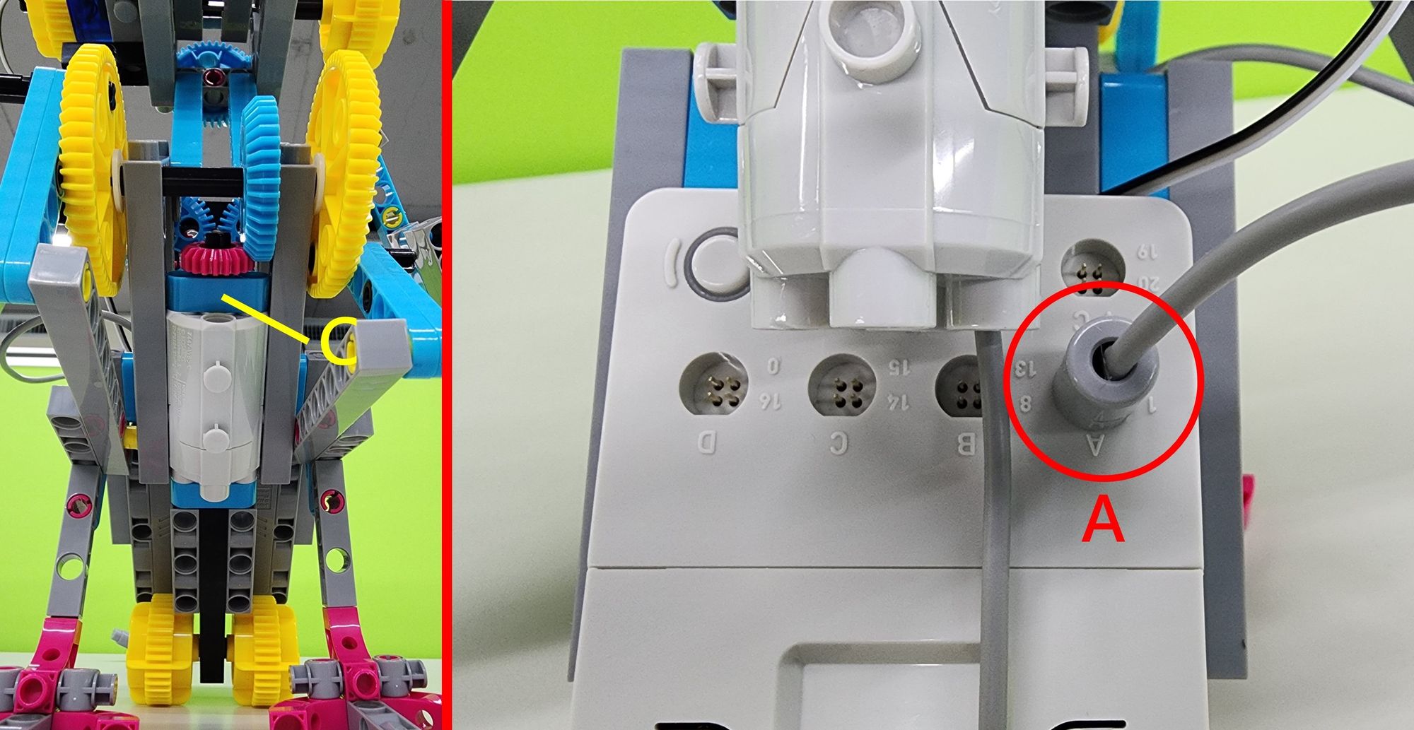
Step 15: Installing the Connectors for the C-50X PLANETARY GEARBOX and the C-180° SERVO MOTOR
In this step, we will install the connectors for the C-50X PLANETARY GEARBOX and the C-180° SERVO MOTOR. First, locate the C-50X PLANETARY GEARBOX from Part C, which controls the bionic bird's feet, and connect its connector to pin A of the C-SMART CONTROLLER as shown (Figure 50).
Next, locate Part L, the C-50X PLANETARY GEARBOX that controls the wings of the bionic bird, and connect its connector to pin B of the C-SMART CONTROLLER as shown (Figure 51).
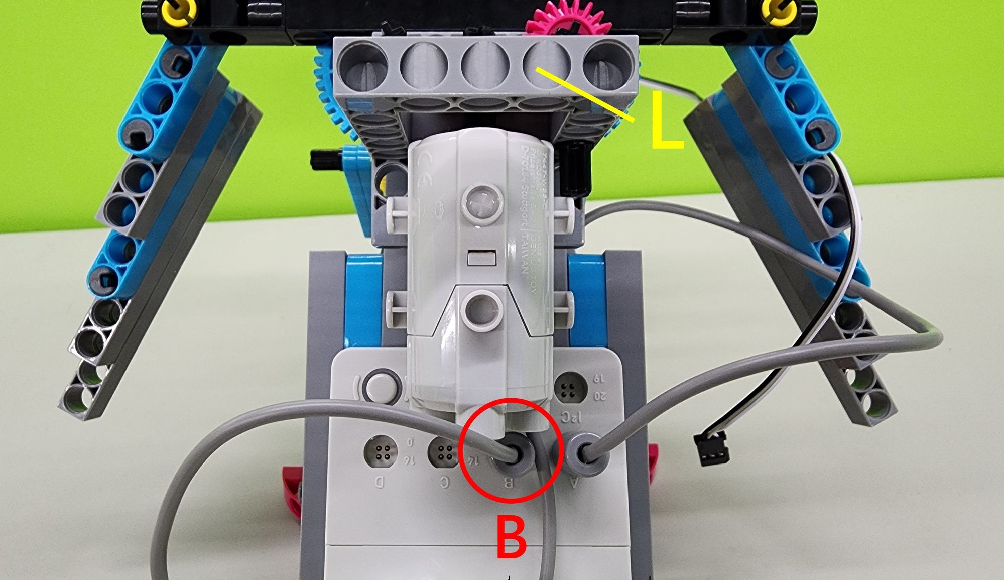
Finally, locate Part M, which controls the C-180° SERVO MOTOR for the bionic bird's beak, and connect its connector to pin 0 of the C-SMART CONTROLLER as shown (Figure 52).
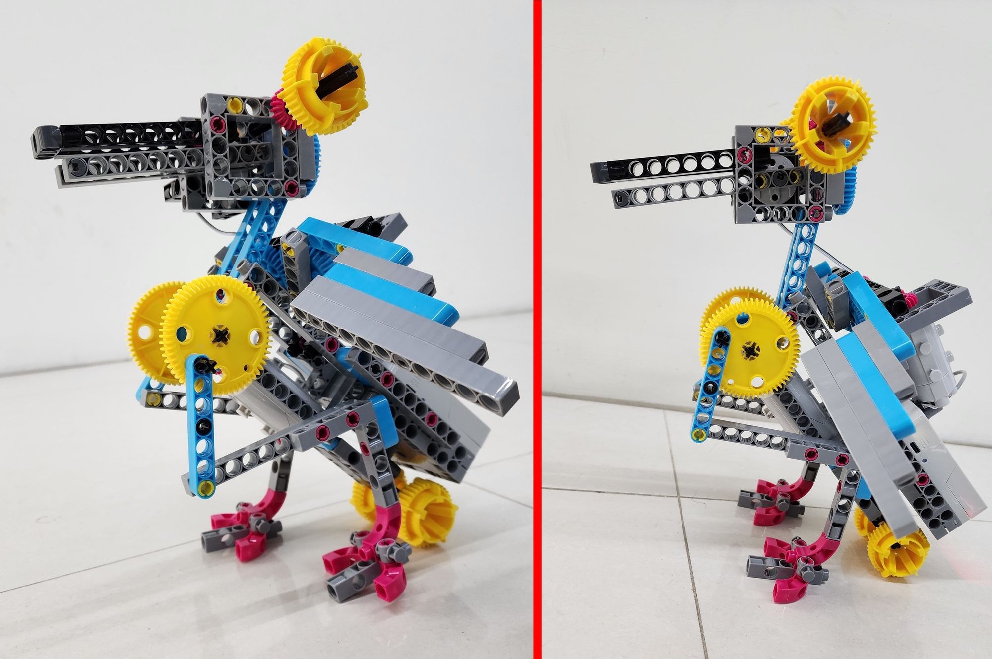
This completes the assembly of the bionic bird (Figure 53). Now, let's move on to writing the program!
◆ Programming
Before getting started, download the "Bionic Bird Sample Program" from the cloud folder below. Then, open the micro:bit programming website and import the file to begin coding.

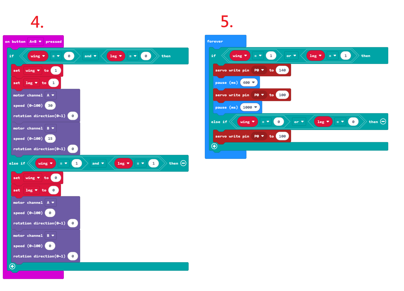
Once the file is successfully imported, you'll see five sets of programming blocks (see Figures 54 and 55). The program functions are explained below:
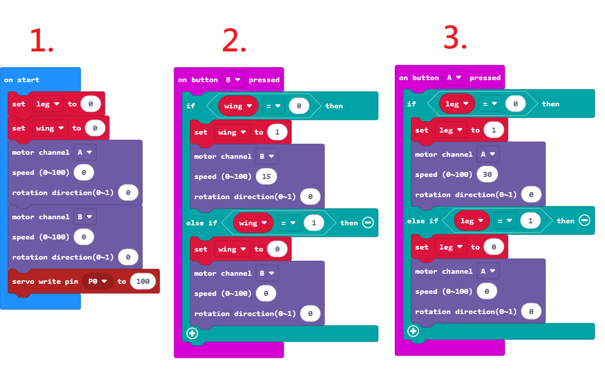
- Motor A controls the bionic bird’s legs, Motor B controls the wings, and the C-180° SERVO MOTOR controls the beak. When the program starts, both Motor A and Motor B are set to a speed of 0 to prevent the bionic bird from accidentally activating. The C-180° SERVO MOTOR is set to 100 degrees to ensure the beak stays closed. The wing and leg variables are both set to 0, which are later used to determine whether Motor A or Motor B should be activated.
- Pressing Button B activates the bird’s wings. The wing variable is set to 1, and Motor B begins rotating at a power of 15, causing the wings to flap. Pressing Button B again resets the wing variable to 0 and stops Motor B, causing the wings to stop flapping.
- Pressing Button A activates the bird’s legs. The leg variable is set to 1, and Motor A begins rotating at a power of 30, making the bird walk. Pressing Button A again resets the leg variable to 0 and stops Motor A, stopping the walking motion.
4. Pressing both Button A and Button B at the same time activates both the wings and legs of the bionic bird. The wing and leg variables are set to 1, Motor A runs at a power of 30, and Motor B runs at a power of 15. This causes the bird to move both its wings and legs simultaneously. Pressing both buttons again resets the variables to 0 and stops both motors, halting all movement.
5. Lastly, the beak is controlled using the same wing and leg variables. As long as either the wings or legs are moving, the beak will also open and close in sync. When both the wings and legs stop, the beak remains closed.
◆ Model Operation
Now let’s bring the bionic bird to life!
As programmed, pressing Button B makes the bird flap its wings and open and close its beak. Press it again to stop the wing and beak movement (see Video 1).
Pressing Button A causes the bird to move its legs along with its beak. Press it again to stop the leg and beak movement (see Video 2).
Pressing both Button A and Button B at the same time activates the wings, legs, and beak all together. Pressing both buttons again will stop all movements (see Video 3).
◆ Troubleshooting
If the bionic bird’s legs are not moving properly, try the following solutions:
- Check whether the leg linkage mechanism and the C-30mm AXLE Ⅱ are assembled correctly (see Step 6).
- Make sure the legs are not hitting other parts during operation, as this can interfere with the linkage movement.
- Operate the bionic bird on a surface with higher friction. If used on a surface that is too smooth, the lack of traction can cause it to slip, affecting its movement.
Adjust the program to increase the speed of Motor A.
If the bionic bird’s wings are not flapping properly, try the following solutions:
- Check that the wing linkage mechanism is assembled correctly.
- Make sure the wings are not colliding with other parts during operation (especially the neck and head), as this can interfere with the movement of the linkage.
Adjust the program to increase the speed of Motor B.
◆ Conclusion
In building this bionic bird model, we explored the concepts of input and output in programming. Inputs are how a system receives data from the outside world — like a keyboard or mouse on a computer. For the bionic bird, the input components are Button A and Button B, which receive commands through physical presses. Outputs are how a system sends information or results to the outside world — such as a computer screen or speaker. In this case, the outputs are the motors and the 180-degree servo motor, which control the bird’s wing flapping, leg movement, and beak opening and closing.
There are so many more ways to explore inputs and outputs! If you're interested in trying out more hands-on projects, check out Gigo's #1409 Robot Workshop - COMPATIBLE WITH micro:bit. You'll get to experiment with a variety of sensors and motors to build all kinds of fun models — all while learning key programming concepts.
That’s it for today’s project! If you enjoyed this guide, don’t forget to share it with your friends — and we’ll see you next time. Bye!
◆Scientific Principles:
The bionic bird model uses a mechanical linkage system. This system consists of levers (various rods) and movable pivot points (axle connectors), which work together to convert the motor’s rotational motion into a rhythmic back-and-forth movement (as shown in Video 4). This principle is what allows the bird’s legs to step forward and its wings to flap up and down.
By adjusting the positions of the levers and pivot points, you can even create entirely different types of movement. Try experimenting — can you come up with your own bionic creature using a different linkage combination?
◆NGSS Curriculum
3-PS2-1 "Plan and conduct an investigation to provide evidence of the effects of balanced and unbalanced forces on the motion of an object."
MS-PS2-2 "Plan an investigation to provide evidence that the change in an object’s motion depends on the sum of the forces on the object and the mass of the object."
MS-ETS1-1 "Define the criteria and constraints of a design problem with sufficient precision to ensure a successful solution, taking into account relevant scientific principles."
3-PS2-4 "Define a simple design problem that can be solved by applying scientific ideas about magnets."
MS-ETS1-4 "Develop a model to generate data for iterative testing and modification of a proposed object, tool, or process such that an optimal design can be achieved."
3-5-ETS1-2 "Construct a device that uses scientific principles to solve a design problem."
◆References
Rivers and Streams: Life in Flowing Water
 Contributors to Wikimedia projects
Please sign in to vote.