Science in daily life: EP14 – Flying Pendulum Clock

Hello, everyone! I’m Teacher Raccoon. Do you remember in Science in Daily Life EP2, we built a gravity-powered pendulum clock using an escapement system? Watching the ticking hands was truly mesmerizing!
Today, I’ll show you how to make another gravity-powered timepiece—the flying pendulum clock. This design first appeared in Leonardo da Vinci’s manuscripts. It works by using a weighted object to pull a rope with a metal ball, which wraps around a pillar in a rhythmic pattern to measure time. Over the years, many have recreated different versions based on his original sketches (Video 1).
Now, let’s build a flying pendulum clock step by step using building blocks!
◆ Assembly Steps
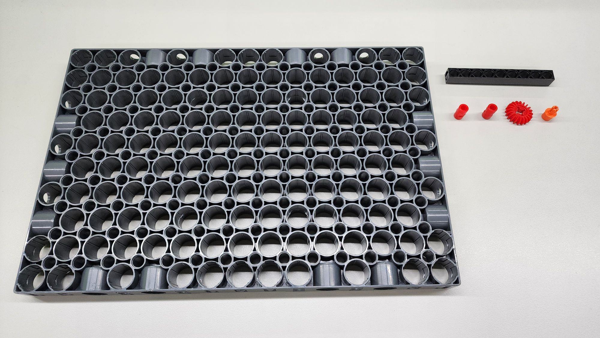
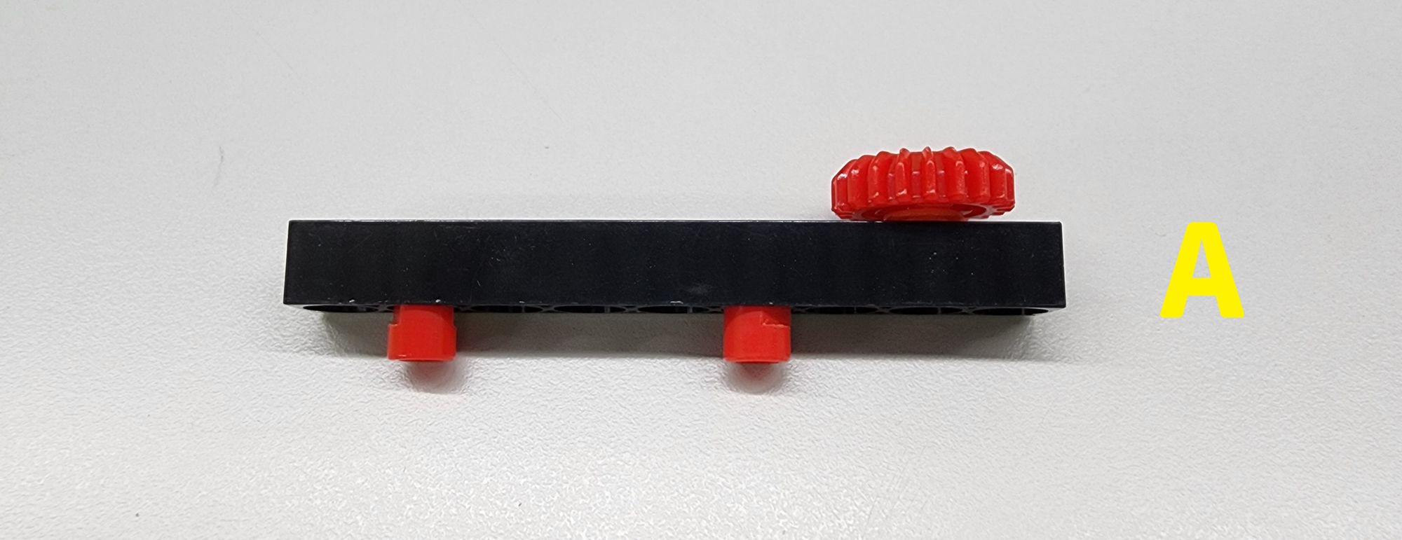
Step 1: We first make the base of the flying pendulum clock. We need to use a C-JUMBO BASE GRID, a C-9 HOLE ROD, one C-AXLE, a C-20T GEAR and two C-LONG PEG (Figure 1). Assemble the parts other than the C-JUMBO BASE GRID into part A (Figure 2) accordingly.
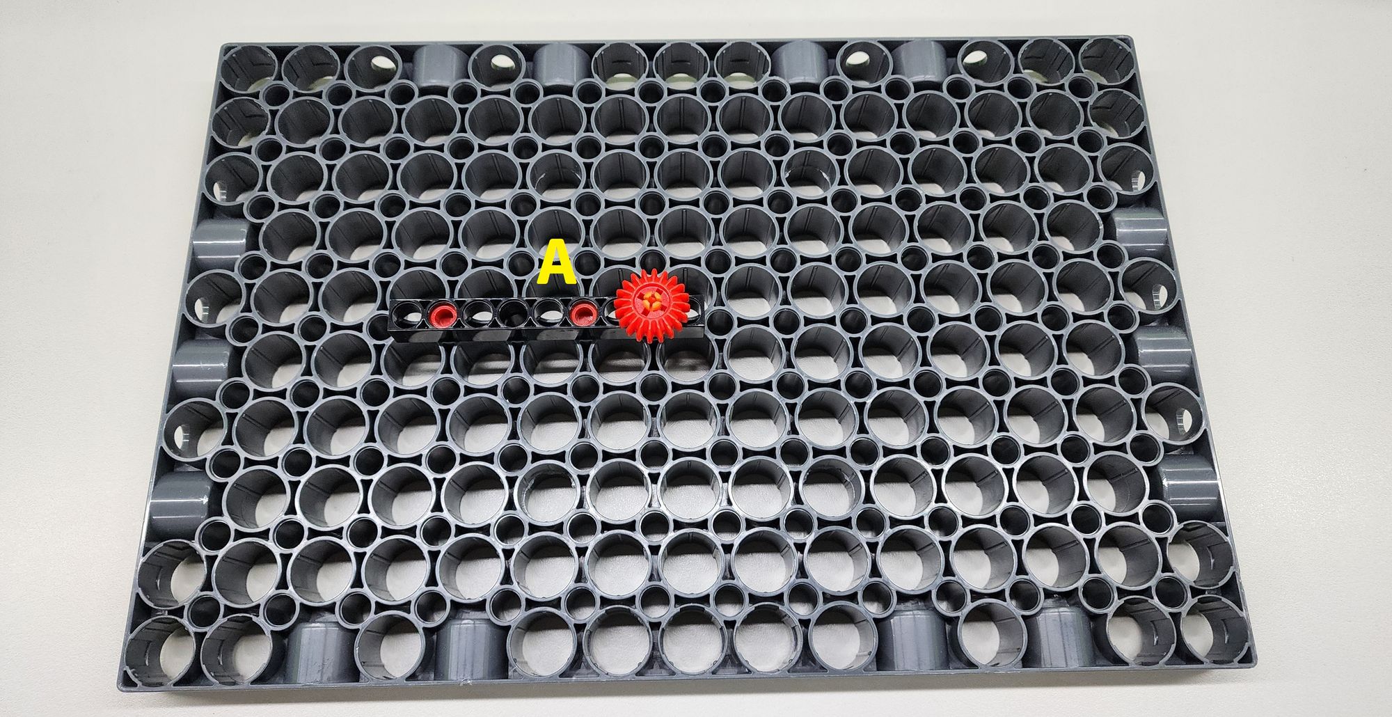
Then install the part A on top of the C-JUMBO BASE GRID as shown (Figure 3).
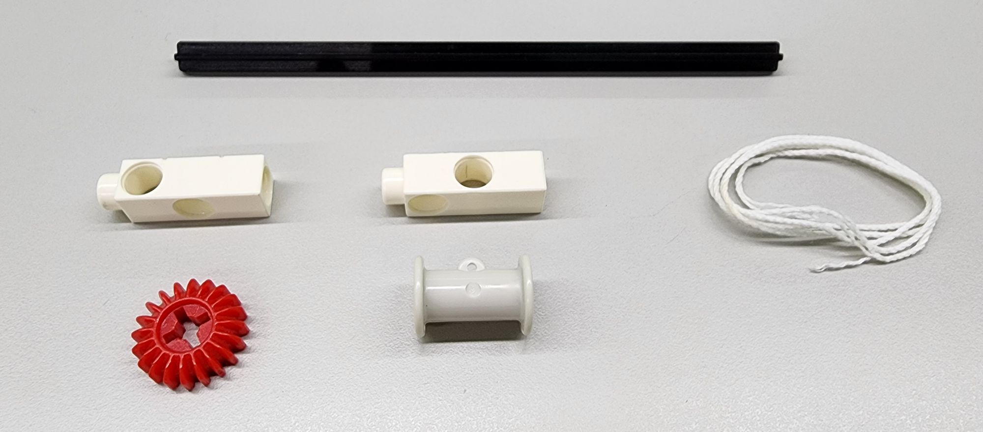
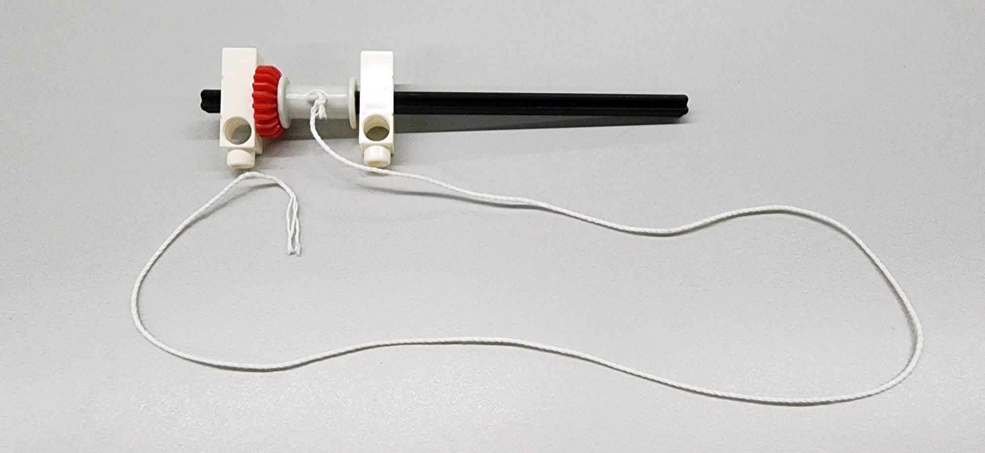
Step 2: We will make the rotating shaft of the flying pendulum clock, which requires a C-150mm AXLEⅠ, two C-3 HOLE DUAL ROD, a C-20T GEAR, a reel and a cotton rope (Figure 4). First, tie one end of the cotton rope to the reel, and then install the parts on the C-150mm AXLEⅠaccordingly. Pay attention to the order of the parts during assembly (Figure 5).
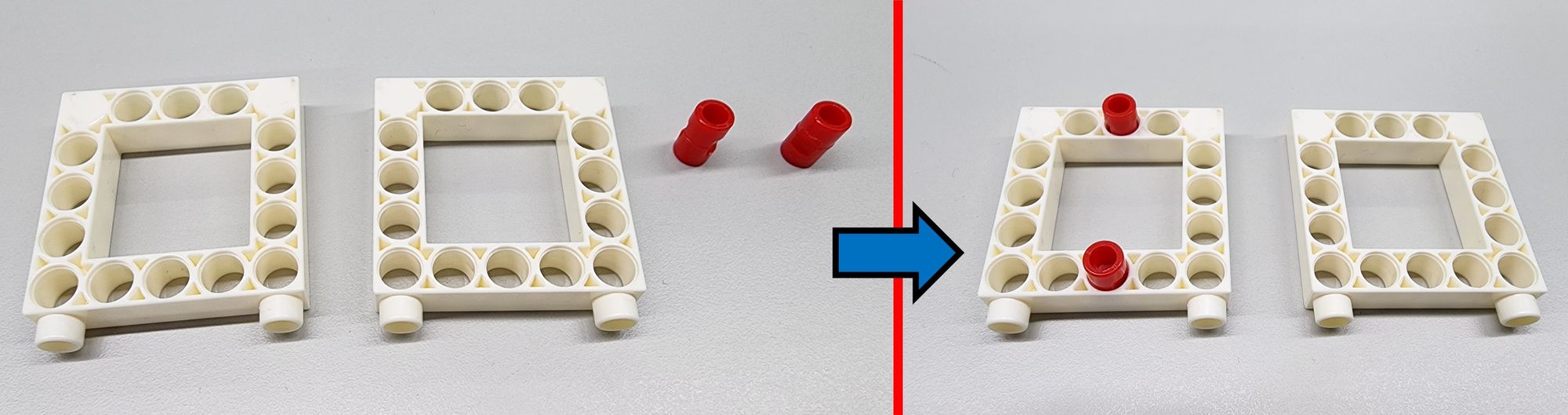
Next, we need to use the C-5×5 FRAME and the C-LONG PEG, and install the two C-LONG PEG on the top of the C-5×5 FRAME accordingly (Figure 6).
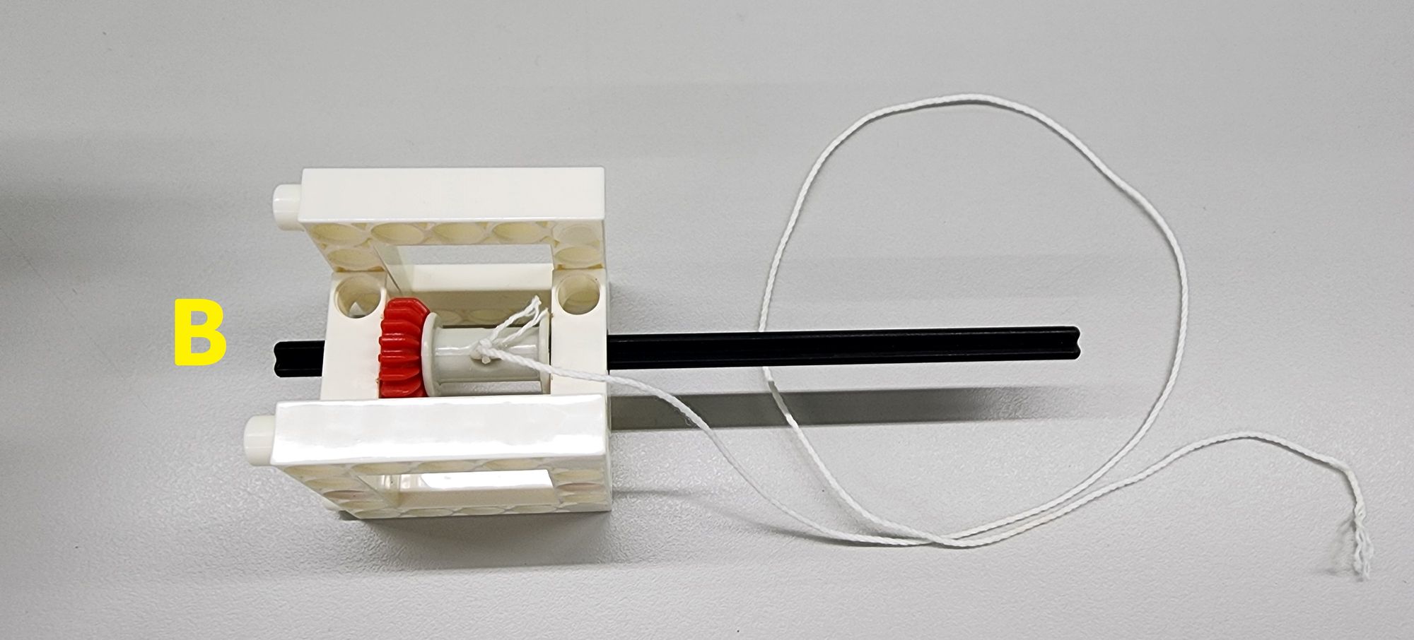
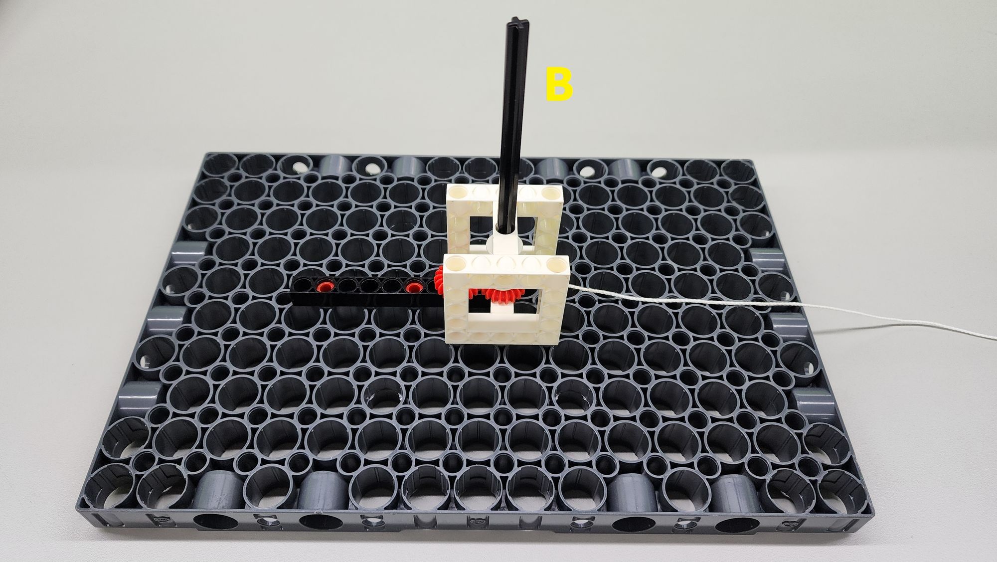
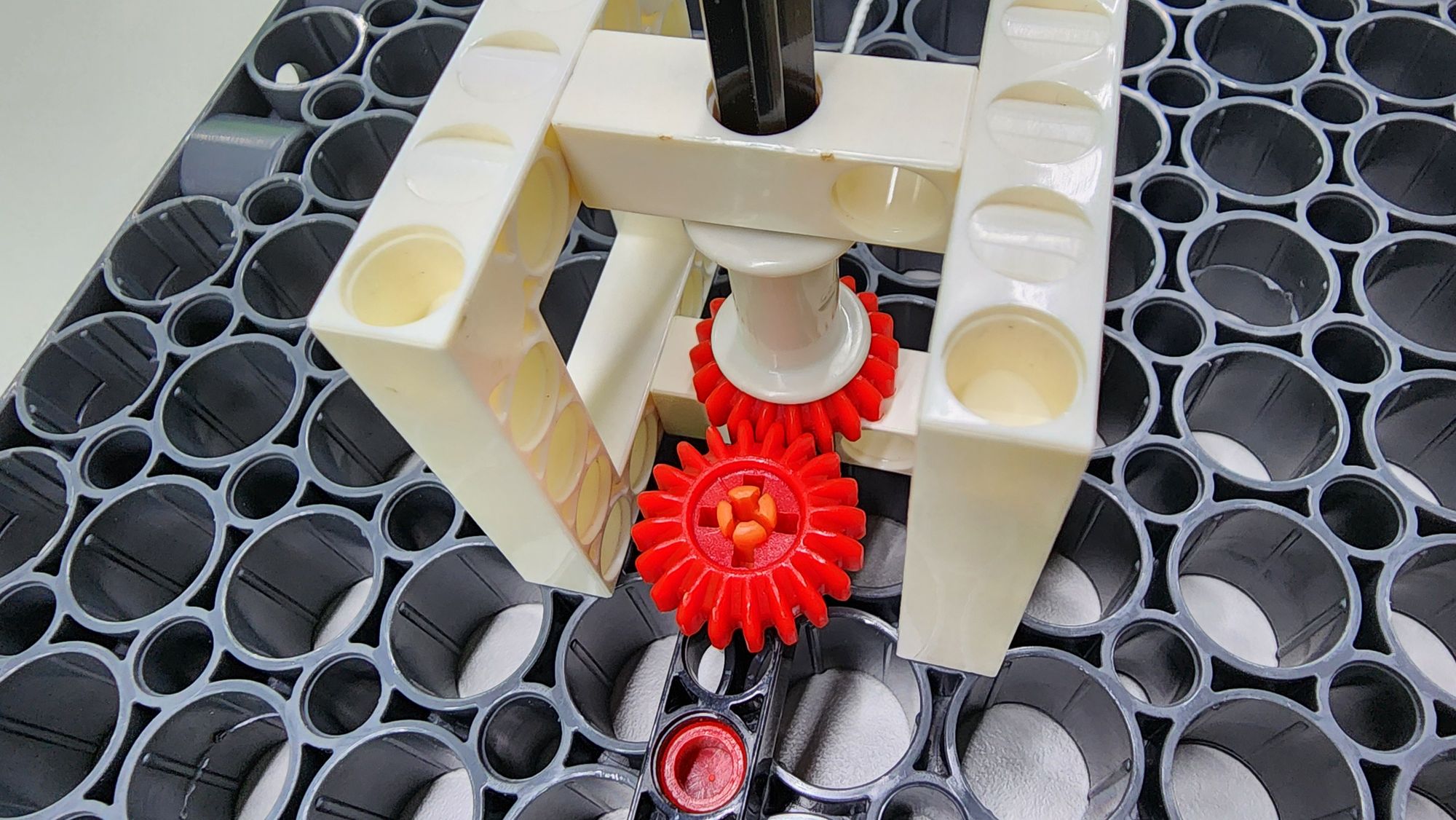
Finally, combine the previously assembled components to complete the production of part B (Figure 7), and install the part B on the top of the C-JUMBO BASE GRID (Figure 8). After completing the fixing of the axle, make sure that the C-20T GEAR of part A and part B are engaged with each other (Figure 9).
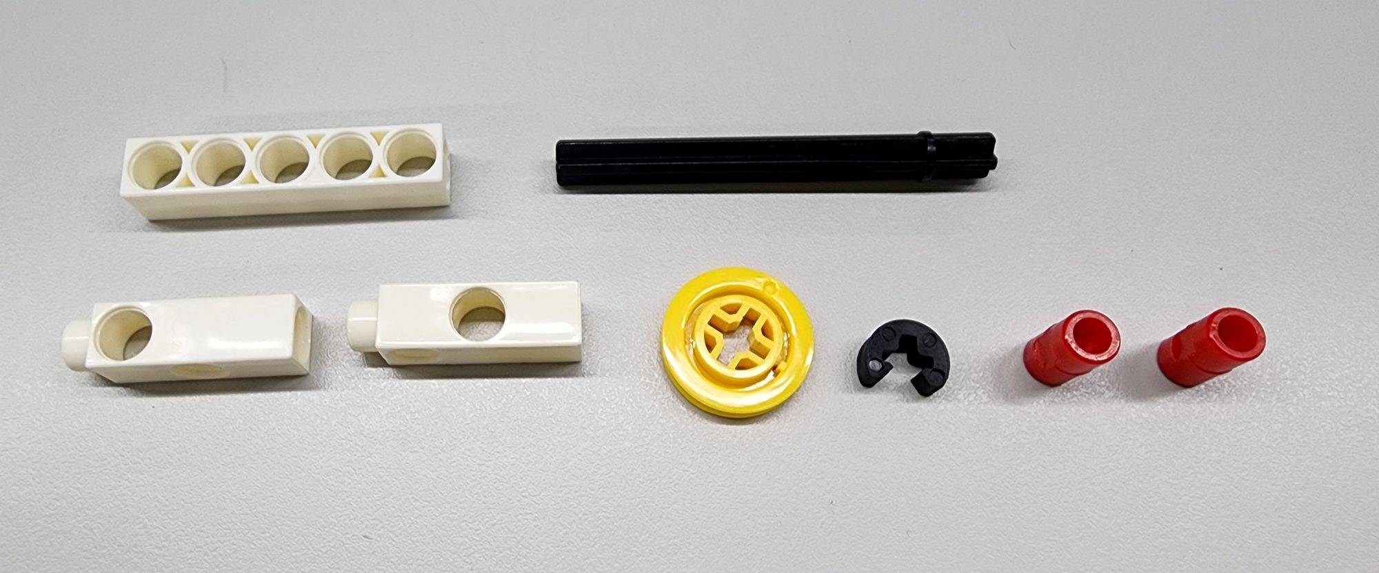
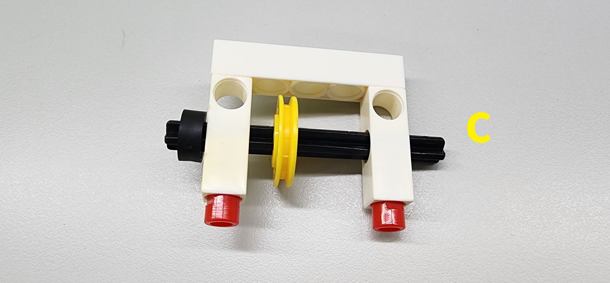
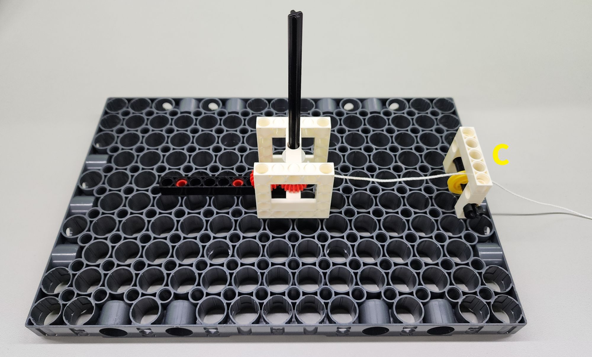
Step 3: We are going to make a simple fixed pulley mechanism, which can change the direction of the force applied by the weight, allowing the weight to fall downward while also pulling the axle with minimal friction. It requires a C-5 HOLE ROD, two C-3 HOLE DUAL ROD, a C-70mm AXLE Ⅱ, an C-OD23mm PULLEY, a C-AXLE FIXING and a C-LONG PEG (Figure 10). Assemble them into part C (Figure 11) accordingly.
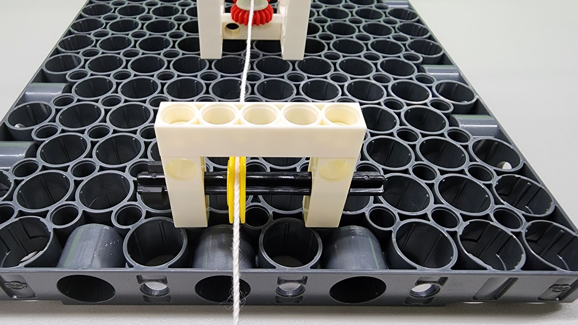
Then install the part C on the C-JUMBO BASE GRID accordingly (Figure 12), and make sure that the cotton rope can accurately enter the groove of the C-OD23mm PULLEY (Figure 13).
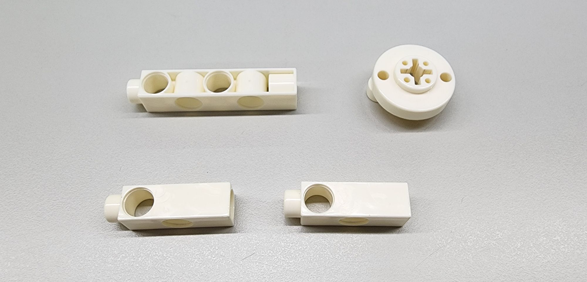
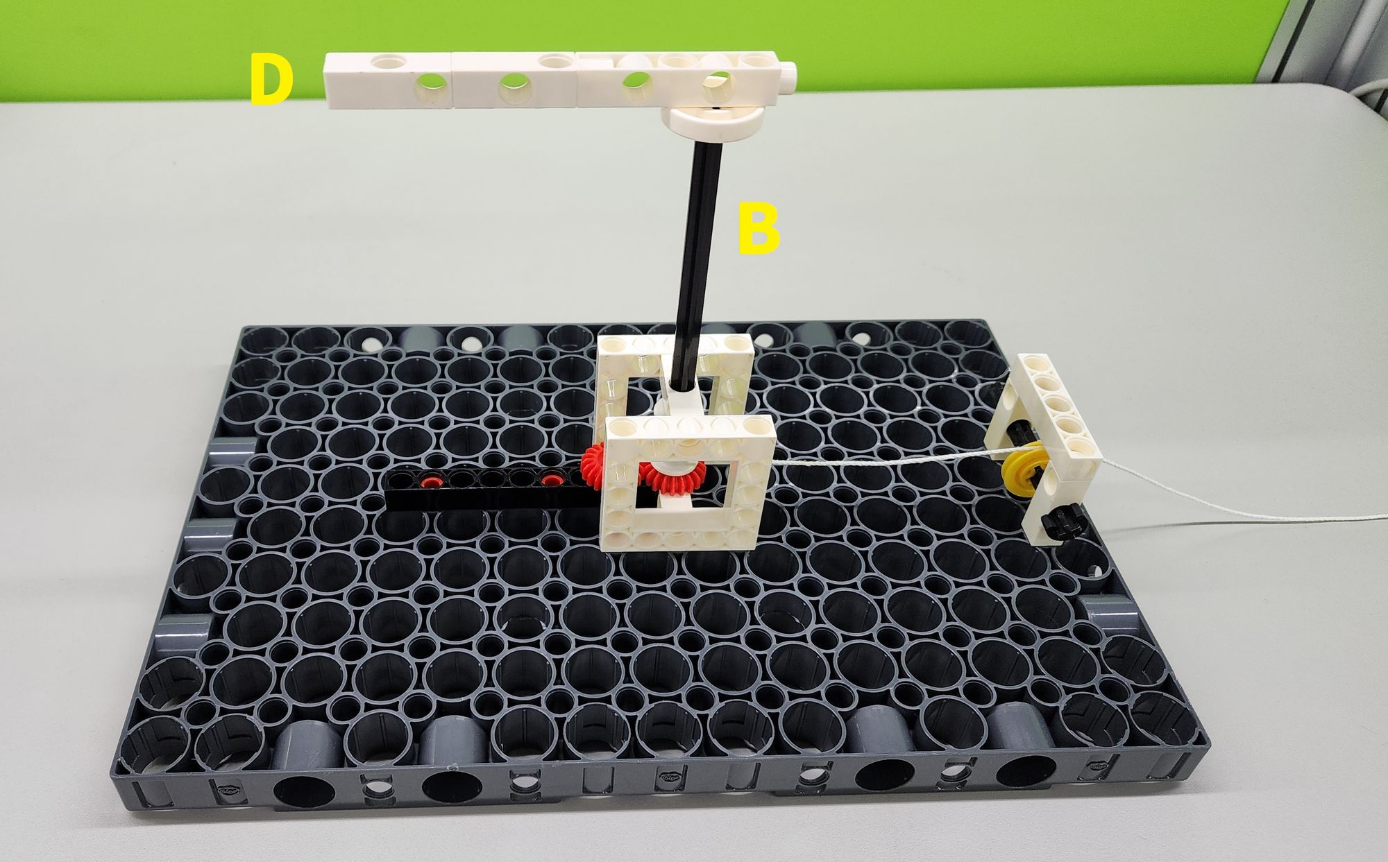
Step 4: We are going to make the bracket of the flying pendulum clock to hang the pendulum. We need to use one C-5 HOLE DUAL ROD, two C-3 HOLE DUAL ROD and the C-ROD CONNECTOR (Figure 14). Assemble them into part D (Figure 15).
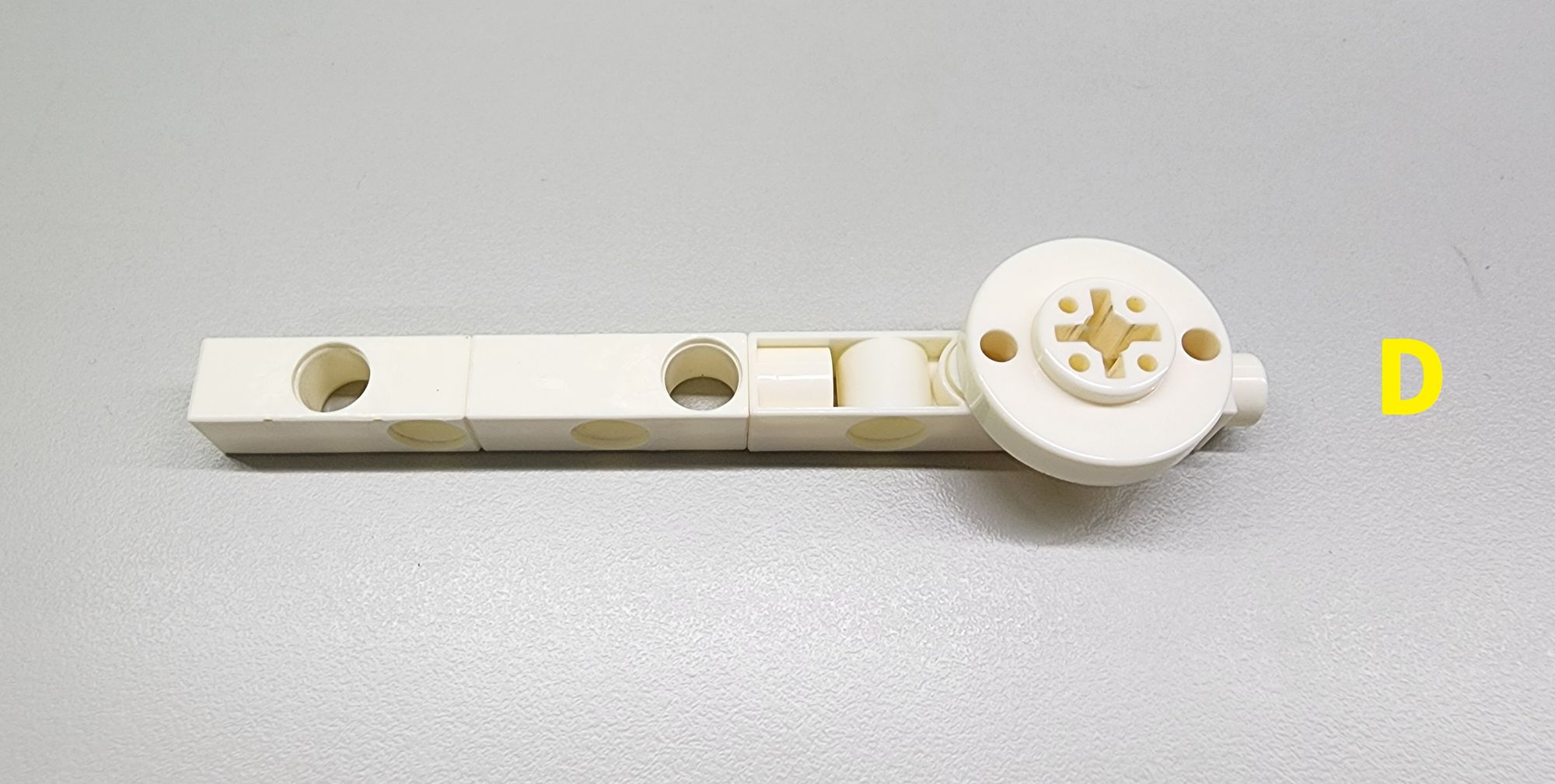
Then, insert the C-ROD CONNECTOR of part D into the C-150mm AXLEⅠ of part B as shown in the figure to complete the installation of the bracket (Figure 16).
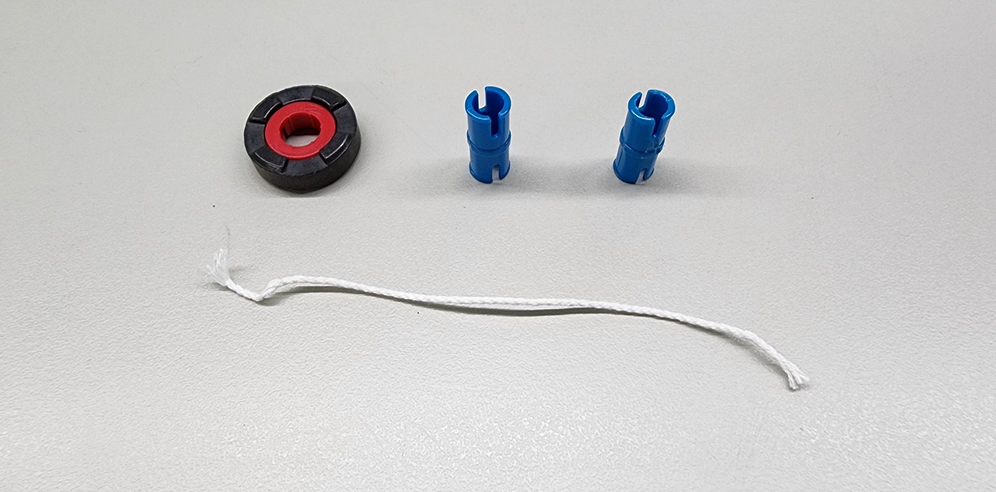
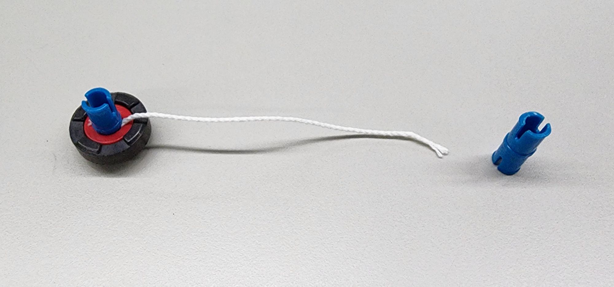
Step 5: We are going to make the pendulum of the flying pendulum clock. Here we use a C-ROUND MAGNET (7065-W85-A). If you don’t have a round magnet, you can also use an iron gasket or marbles instead. In addition, you will need two C-20mm AXLE CONNECTOR and a cotton rope about 10~12cm long (Figure 17). Use the C-20mm AXLE CONNECTOR to fix the cotton rope on the round magnet as shown (Figure 18).
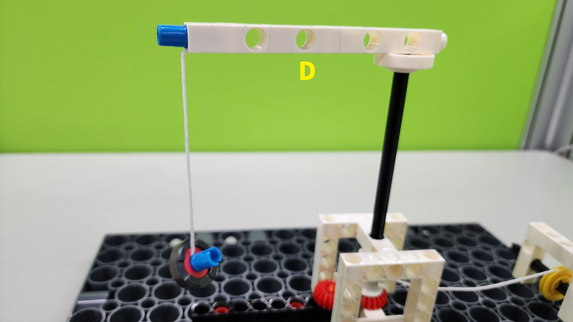
Then, use another C-20mm AXLE CONNECTOR to fix the cotton rope to part D as shown to complete the installation of the pendulum (Figure 19).
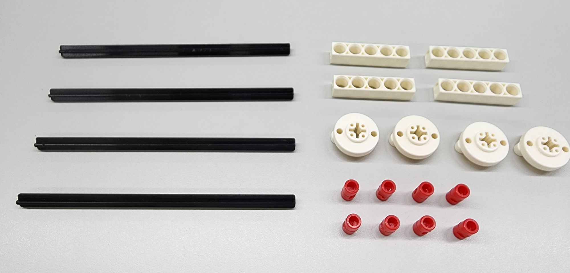
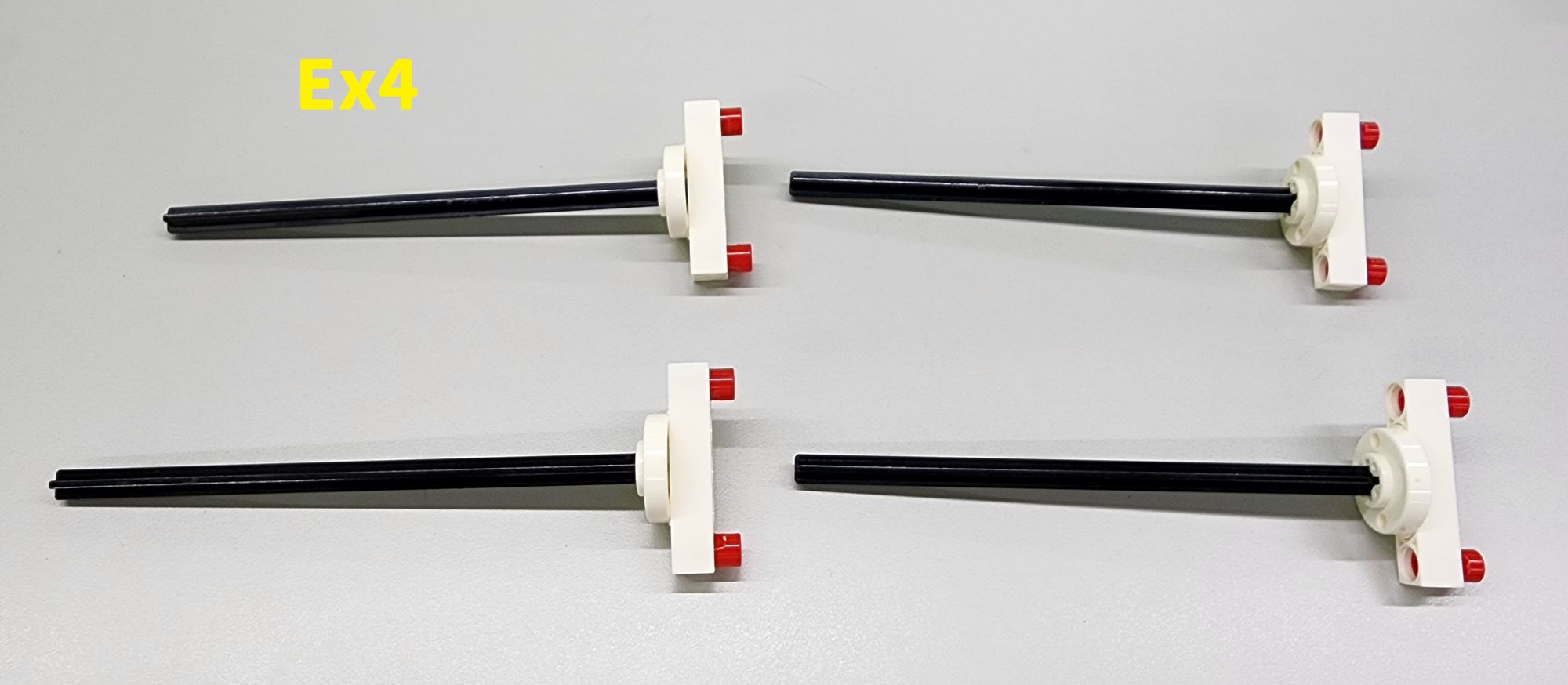
Step 6: We are going to make the four outer pillars of the flying pendulum clock. We need to use some C-150mm AXLEⅠ, some C-5 HOLE ROD, some C-ROD CONNECTOR and C-LONG PEG (Figure 20). Assemble them into four parts E (Figure 21) as shown.
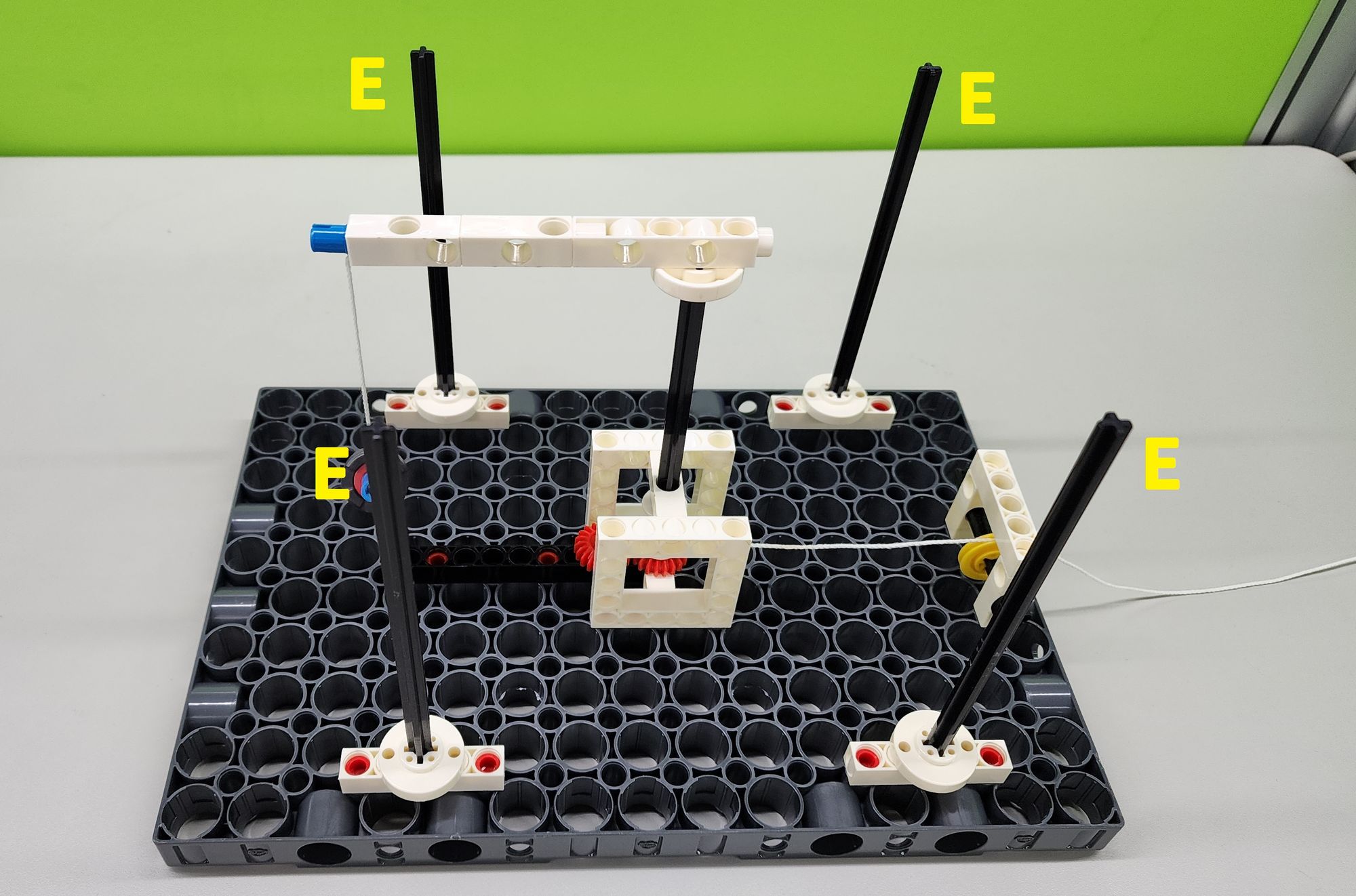
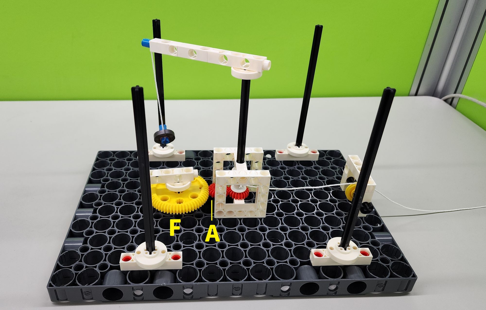
Then install the four parts E on top of the C-JUMBO BASE GRID (Figure 22) to complete the installation of the pillars.
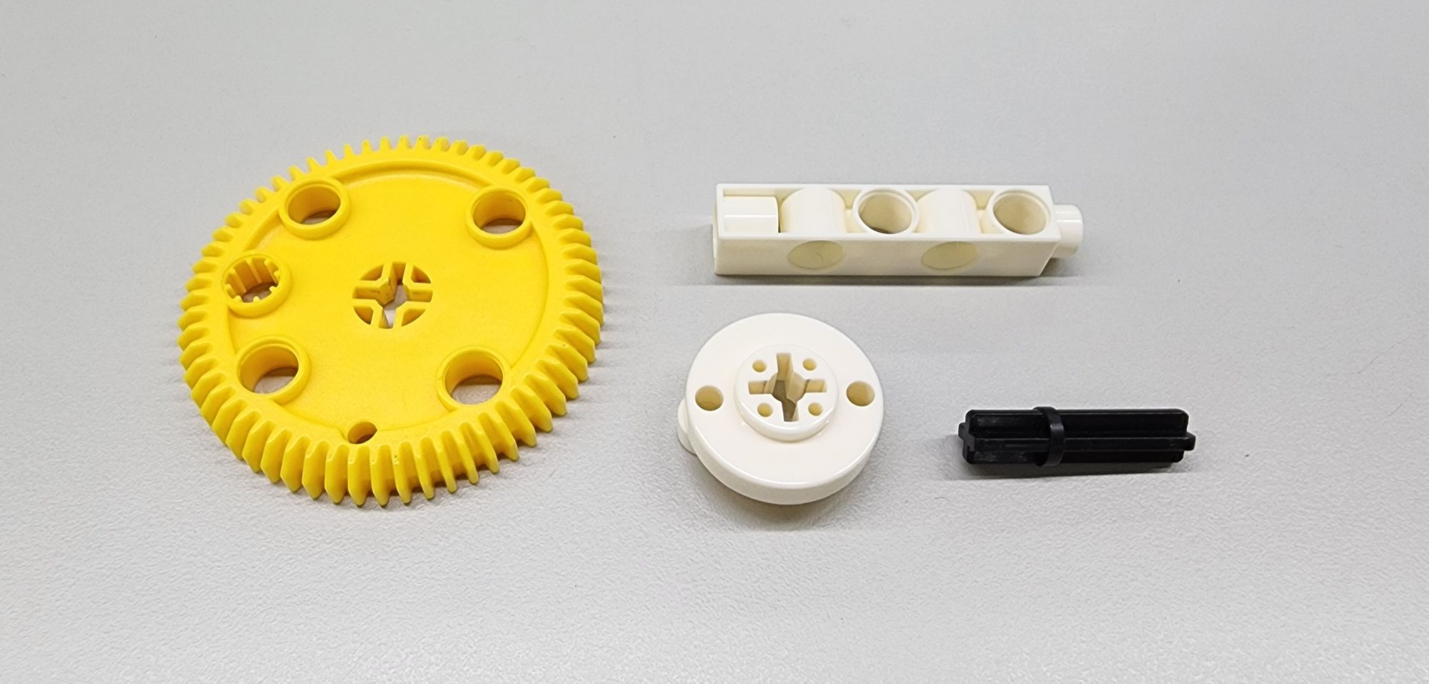
Step 7: We are going to make the pointer of the flying pendulum clock. We need to use the C-5 HOLE DUAL ROD, C-60T GEAR, C-30mm AXLE Ⅱ, and C-ROD CONNECTOR (Figure 23). Assemble them into part F(Figure 24) accordingly.
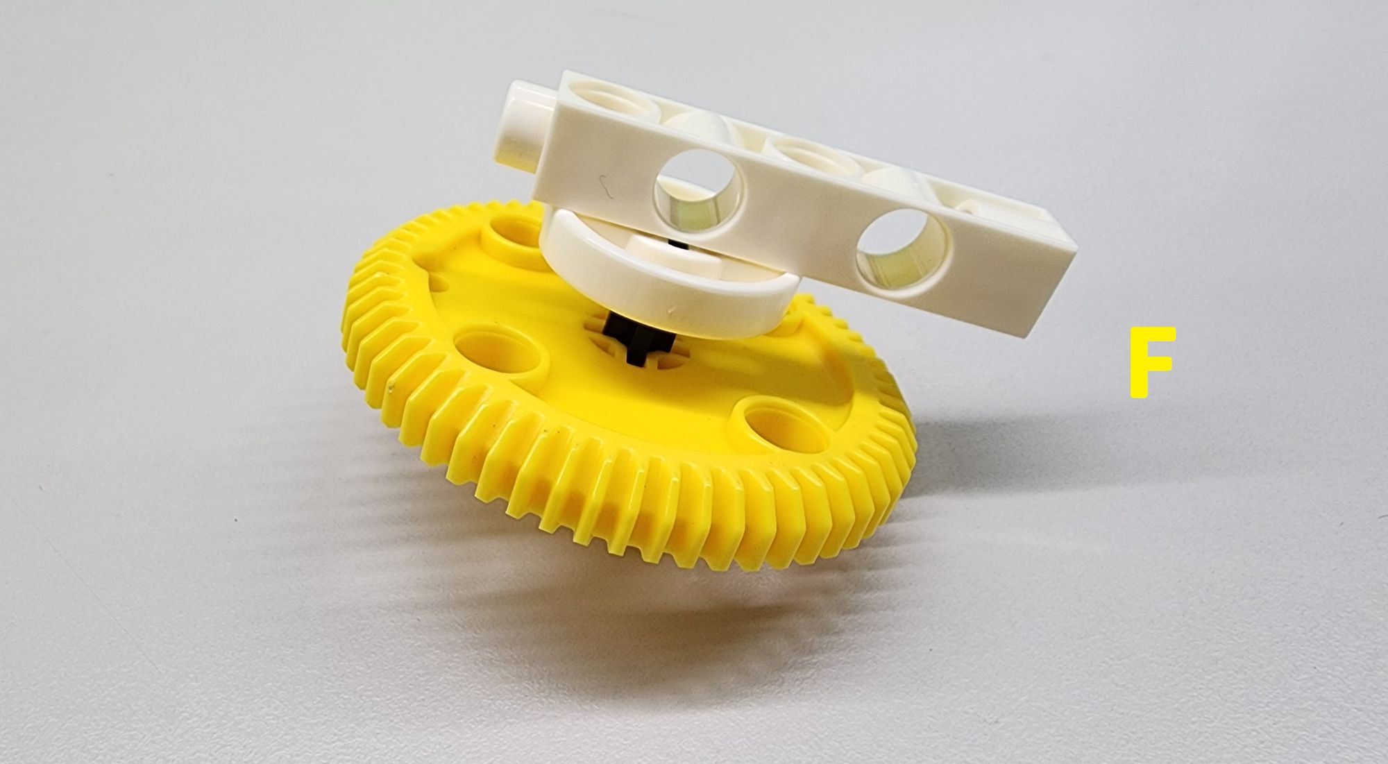
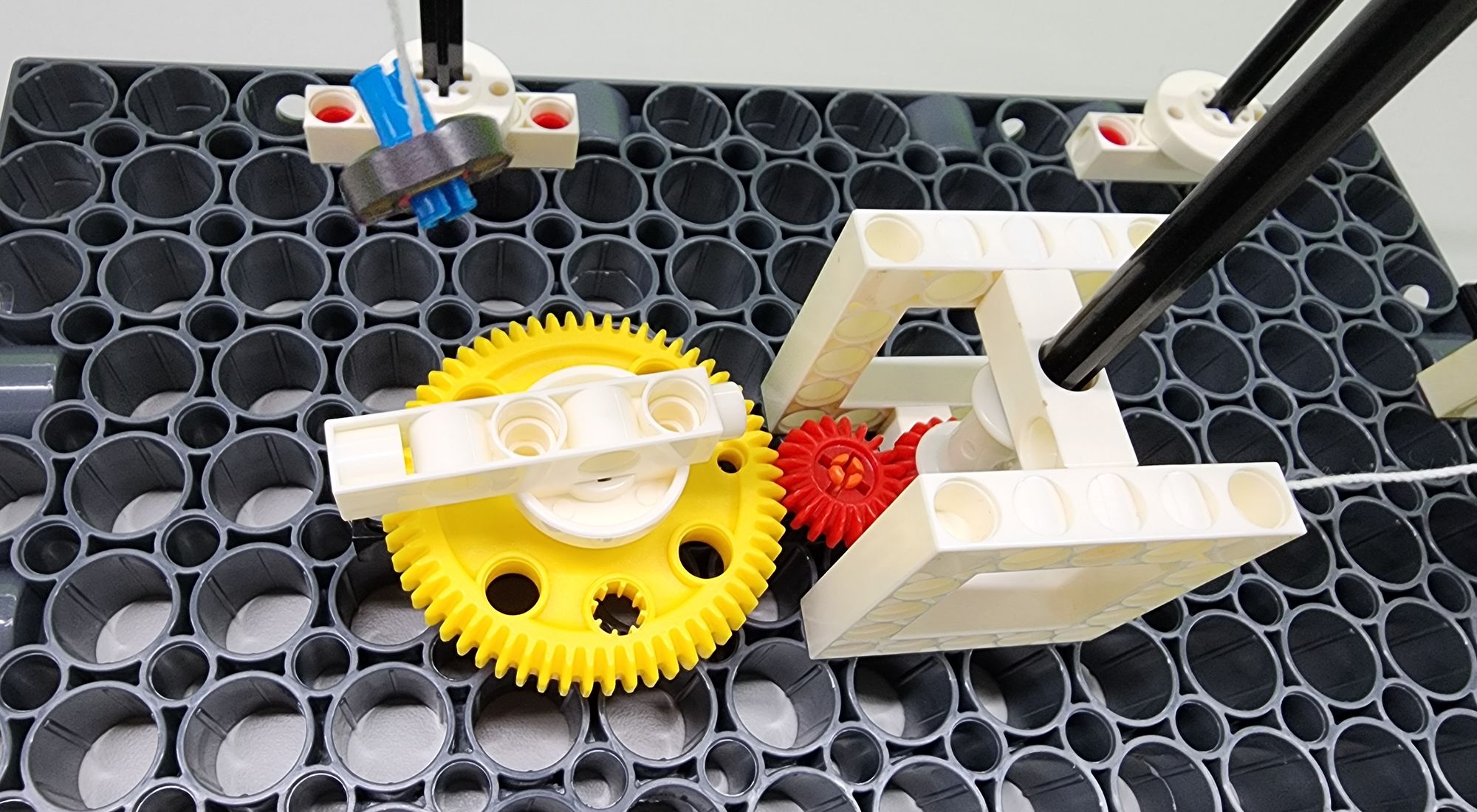
Then install part F on top of the C-9 HOLE ROD of part A as shown (Figure 25), complete the installation of the pointer, and ensure that the C-60T GEAR of part F meshes with the C-20T GEAR of part A (Figure 26).
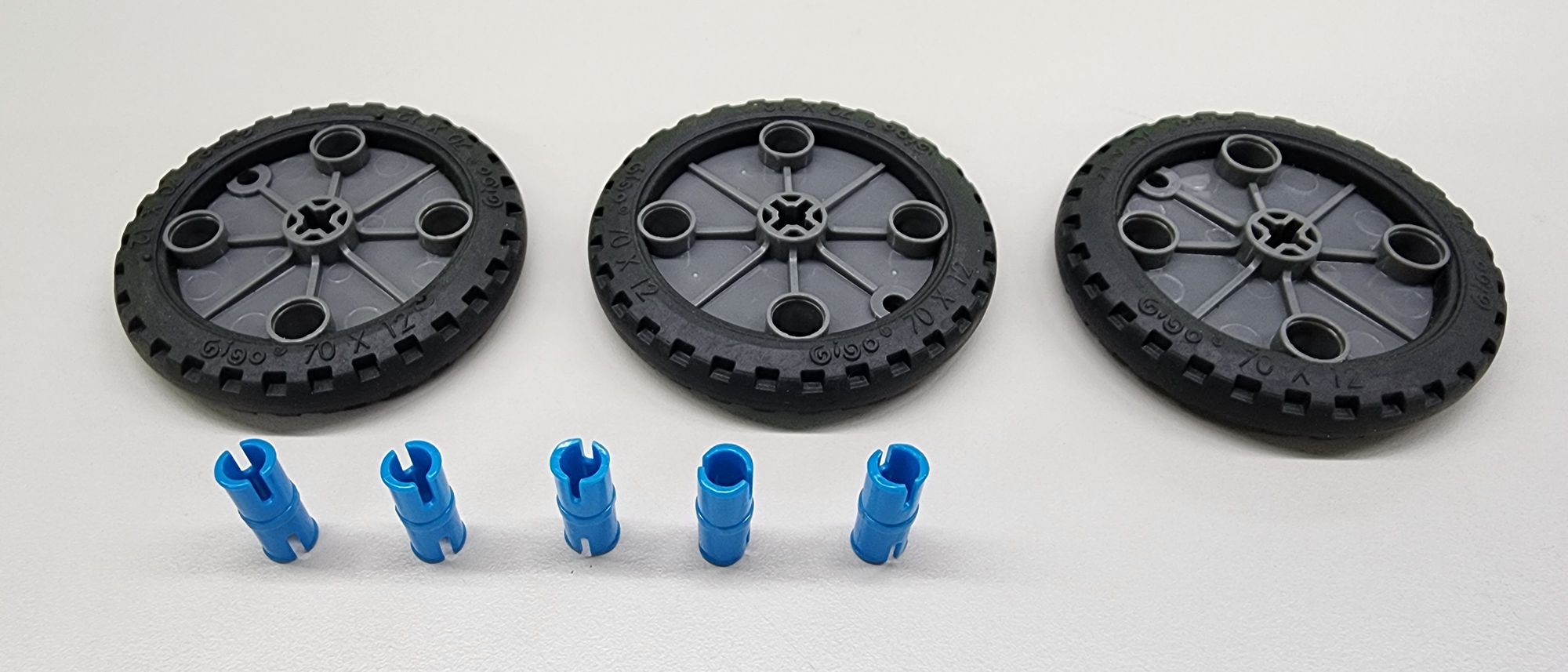
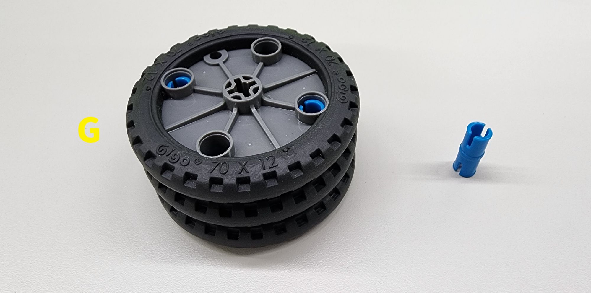
Step 8: We are going to make the weight of the flying pendulum clock. We need to use the C-RACING TIRE and C-20mm AXLE CONNECTOR (Figure 27). Assemble them into part G accordingly and keep a C-20mm AXLE CONNECTOR (Figure 28).
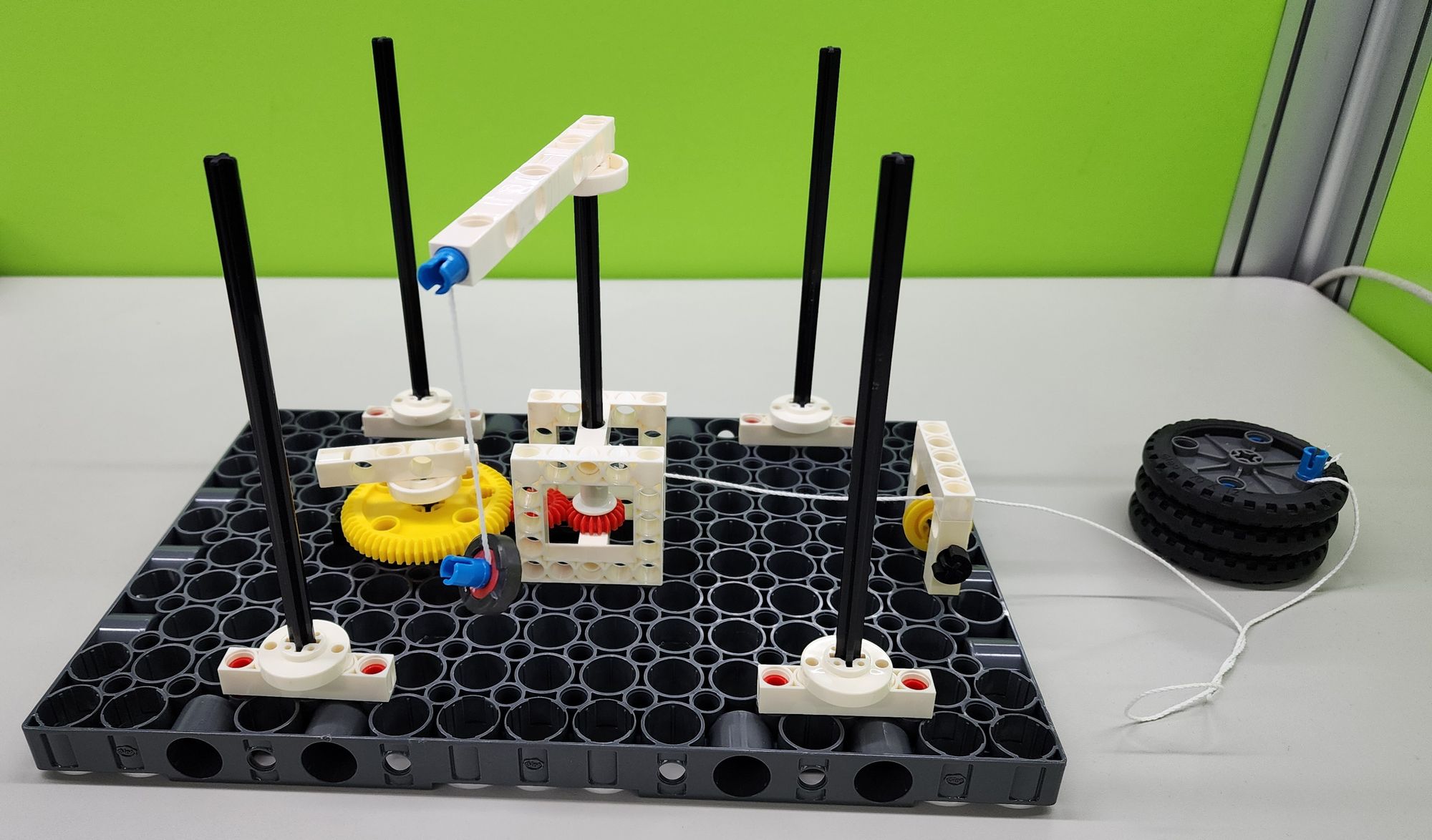
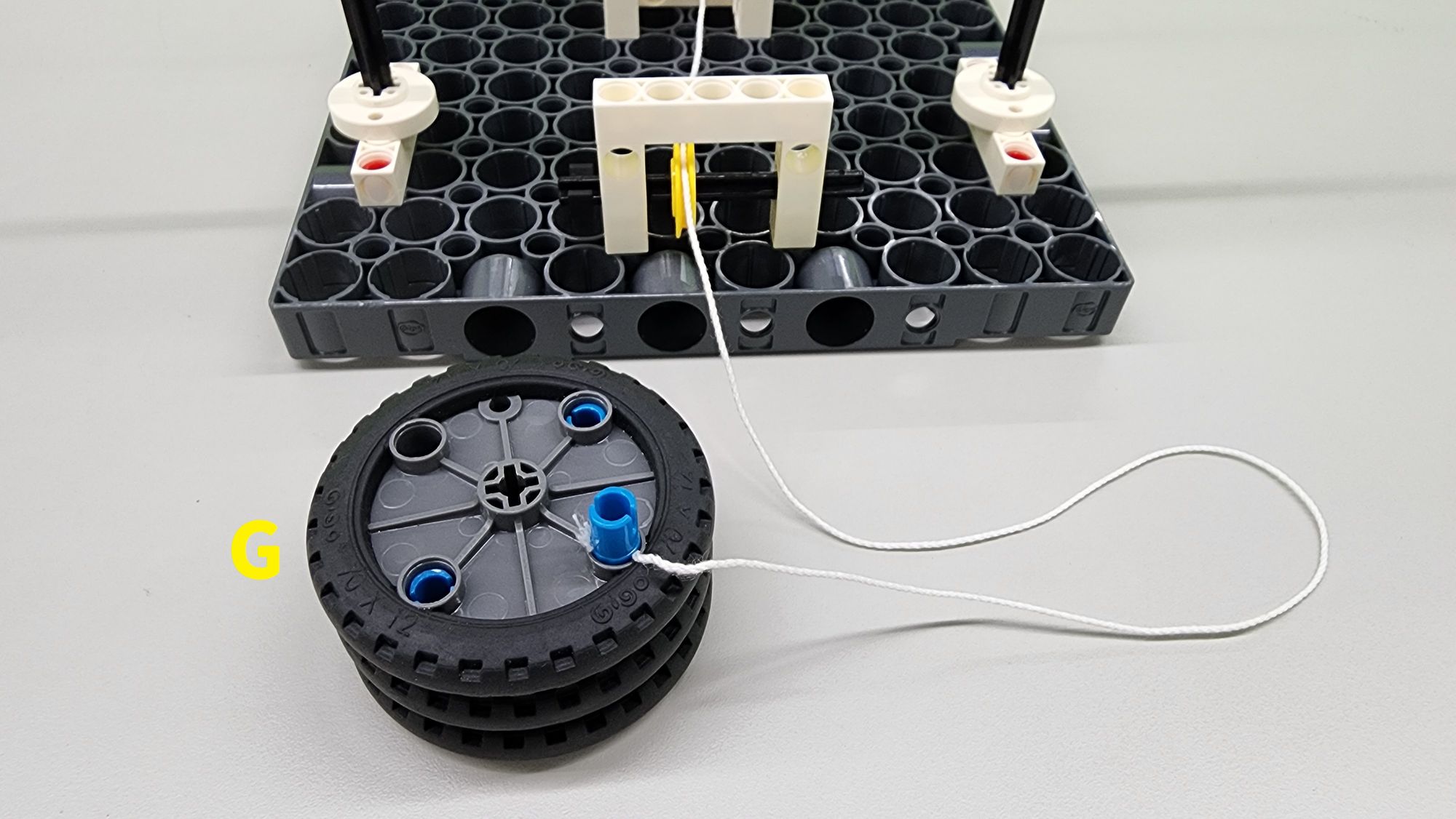
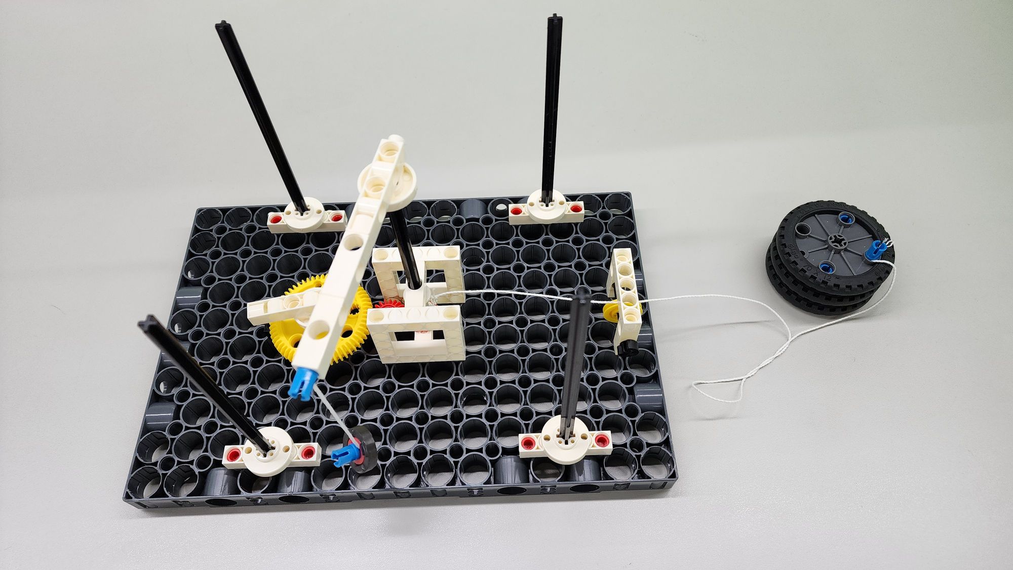
Then, use the C-20mm AXLE CONNECTOR to fix the cotton rope to part G as shown to complete the installation of the weight (Figure 29). In this way, the flying pendulum clock is completed (Figure 30)!
◆ Model operation
Remember how we had to 'wind up' the gravity pendulum clock before operating it?
That’s right! The flying pendulum clock also requires winding—by rolling up a heavy object.
To do this, place the model at the edge of a table and hang the weight underneath, ensuring the cotton rope properly enters the groove of the C-OD23mm PULLEY. Next, remove the bracket above the C-150mm AXLEⅠ and rotate the axle counterclockwise. Once all the cotton rope is wound using the winder, reinstall the bracket.
Now, the winding process is complete! (See Video 2.)
Once the clock is wound up, we can observe the fascinating motion of the flying pendulum clock.
When running smoothly, the pendulum winds around the four pillars in sequence, creating a rhythmic movement (Video 3), much like an escapement mechanism. This consistent motion is then transmitted to the pointer through a series of gears.
As you watch the pointer, you’ll notice it rotates at a steady frequency, just like the second hand of a clock (Video 4). Now, try this: How many rotations does the pointer complete in one full cycle? How much time has passed?
◆ Conclusion
This flying pendulum clock model helps us understand that even the same invention can incorporate different mechanisms and principles. Take clocks for example—they come in many forms based on their timing methods and structures, such as water clocks, hourglasses, pendulum clocks, electronic clocks, atomic clocks, and radio clocks. Each type has its own strengths and limitations, allowing us to choose the most suitable one for our needs.
As technology advances, clocks have evolved from large structures to compact wristwatches. What kinds of clocks do you think we might see in the future?
That’s all for today’s exploration! If you enjoyed this article, don’t forget to share it with your friends. See you next time—bye!
◆ Scientific Principles
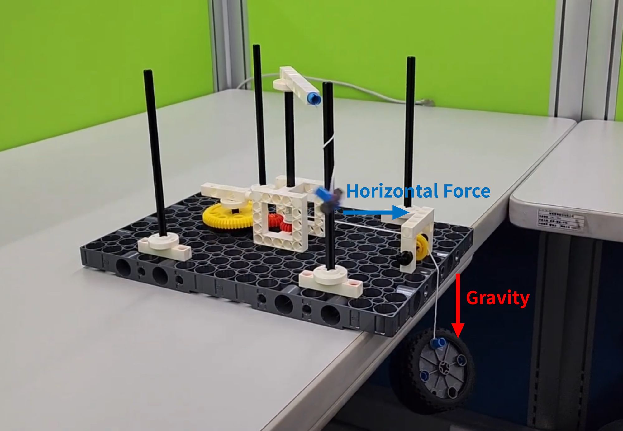
The flying pendulum clock model operates based on the principles of gravity, fixed pulleys, and inertia.
When we release the heavy object, gravity exerts a downward force. The fixed pulley redirects this force, converting it into a horizontal force (Figure 31). This force drives the axle, bracket, and pendulum to rotate. As the cotton rope strikes a pillar, the pendulum's inertia causes the rope to wrap around it, resulting in the axle rotating at a consistent frequency or with a slight time delay.
Now, let’s experiment!
- What happens if we remove all four pillars—will the axle still rotate regularly?
- Try adjusting variables such as the length of the cotton rope, the pendulum's weight, or the weight of the heavy object. Do these changes affect the axle’s rotation frequency? Observe and find out!
◆ Curriculum Reference:
MS-ETS1-3. Analyze data from tests to determine similarities and differences among several design solutions to identify the best characteristics of each that can be combined into a new solution to better meet the criteria for success.
MS-PS2-2. Plan an investigation to provide evidence that the change in an object’s motion depends on the sum of the forces on the object and the mass of the object.
MS-PS3-5. Construct, use, and present arguments to support the claim that when the kinetic energy of an object changes, energy is transferred to or from the object.
3-PS2-4. Define a simple design problem that can be solved by applying scientific ideas about magnets.
◆ References
 Contributors to Wikimedia projects
 Contributors to Wikimedia projects
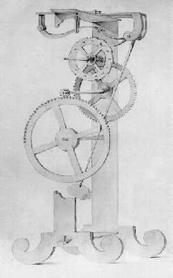


Please sign in to vote.