Science in daily life: EP12 – Claw machine(#1206)

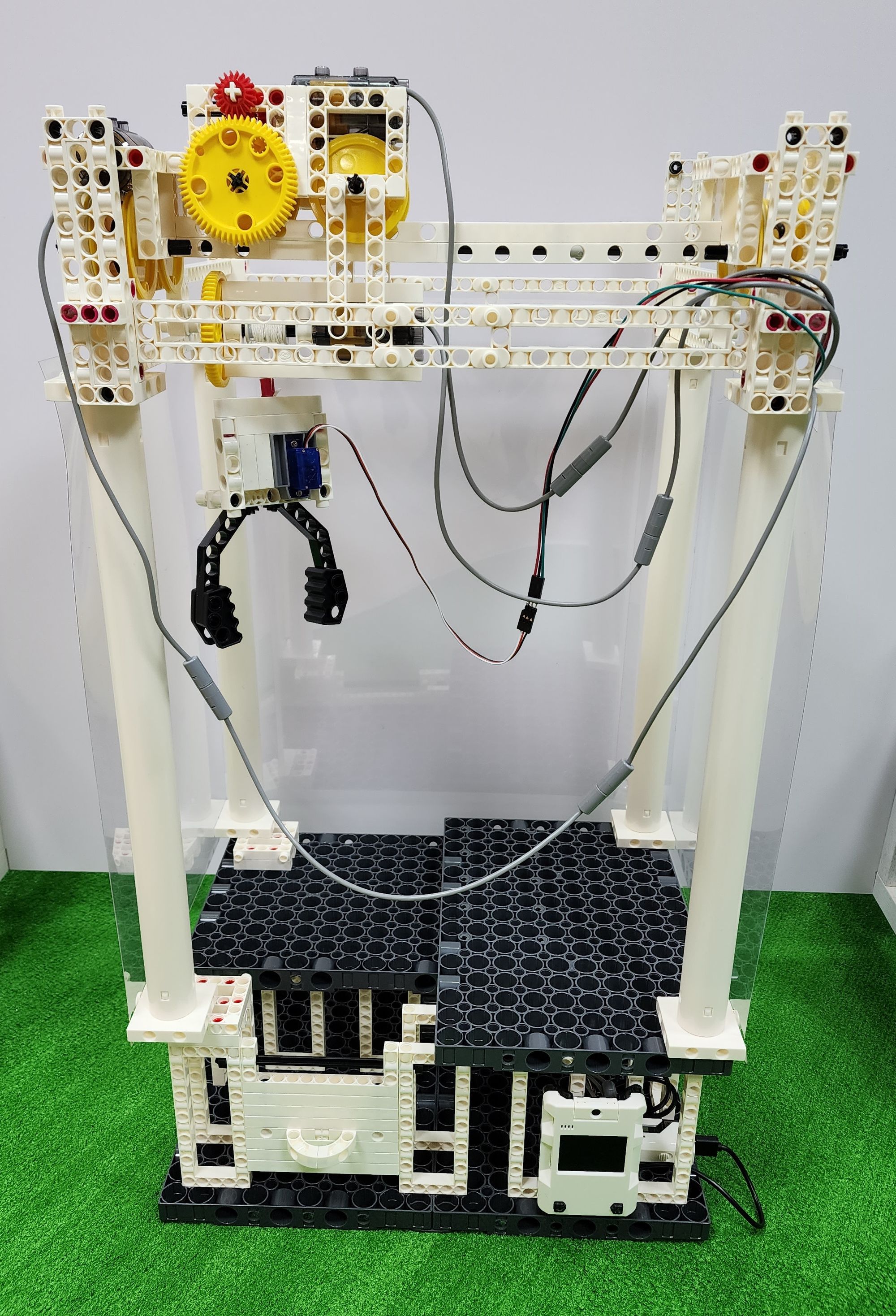
Hello everyone, I'm Teacher Raccoon. Have you noticed the proliferation of claw machine stores in Taiwan in recent years? At its peak, you could even see several of them lining the same street. Have you ever played with a claw machine? It's an entertainment device equipped with a grabbing mechanism. After inserting a ten-dollar coin, you use a joystick to grab items within a limited time frame, such as plush toys, dolls, food, daily necessities, and more. Successfully grabbing an item allows you to obtain it, and the difficulty of success is set by the machine's owner. Figuring out how to grab items with the least amount of money spent tests players' skills and luck. Now, let Teacher Raccoon guide you step by step on how to make a claw machine!

◆Assembly Steps
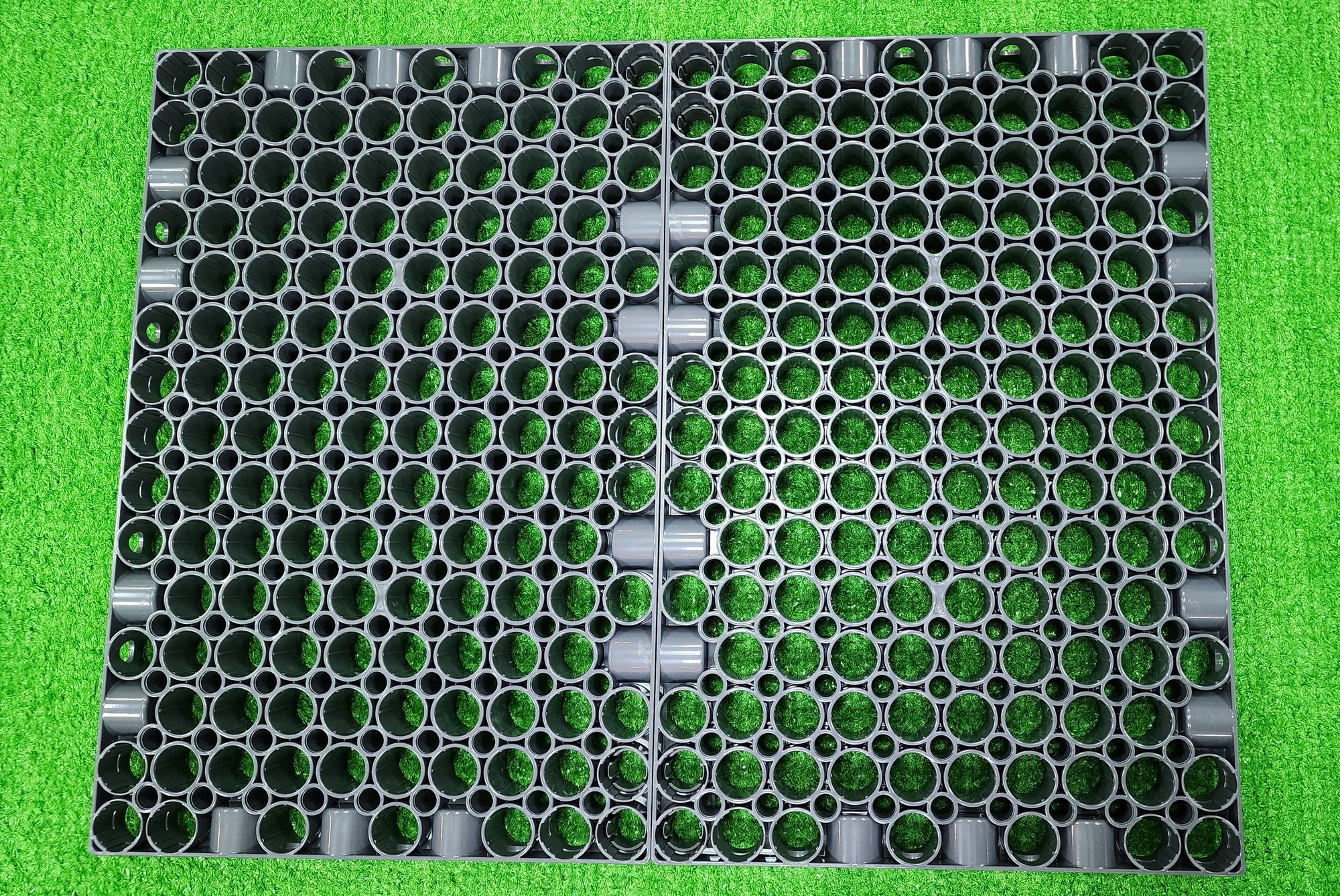
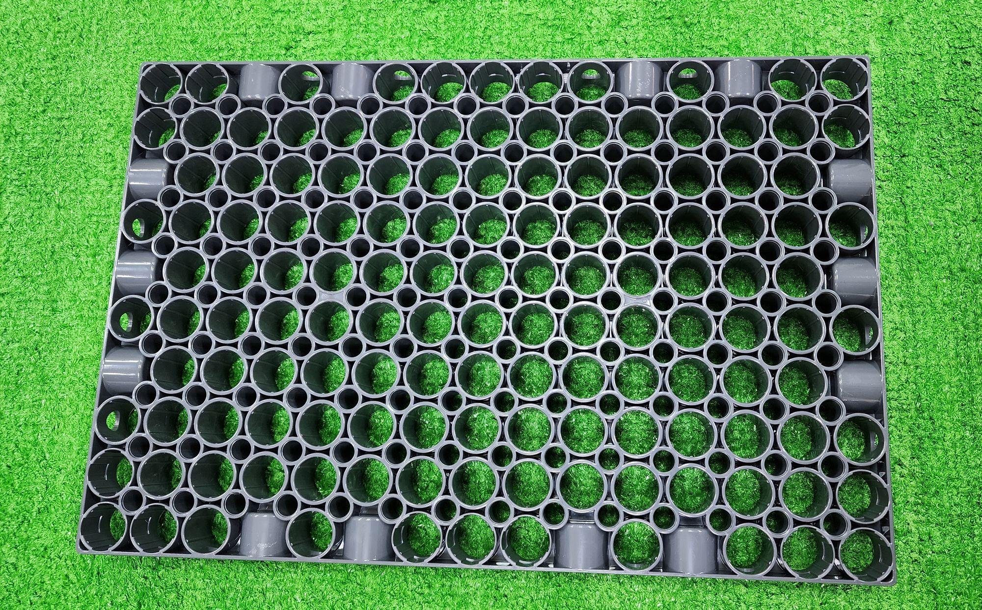
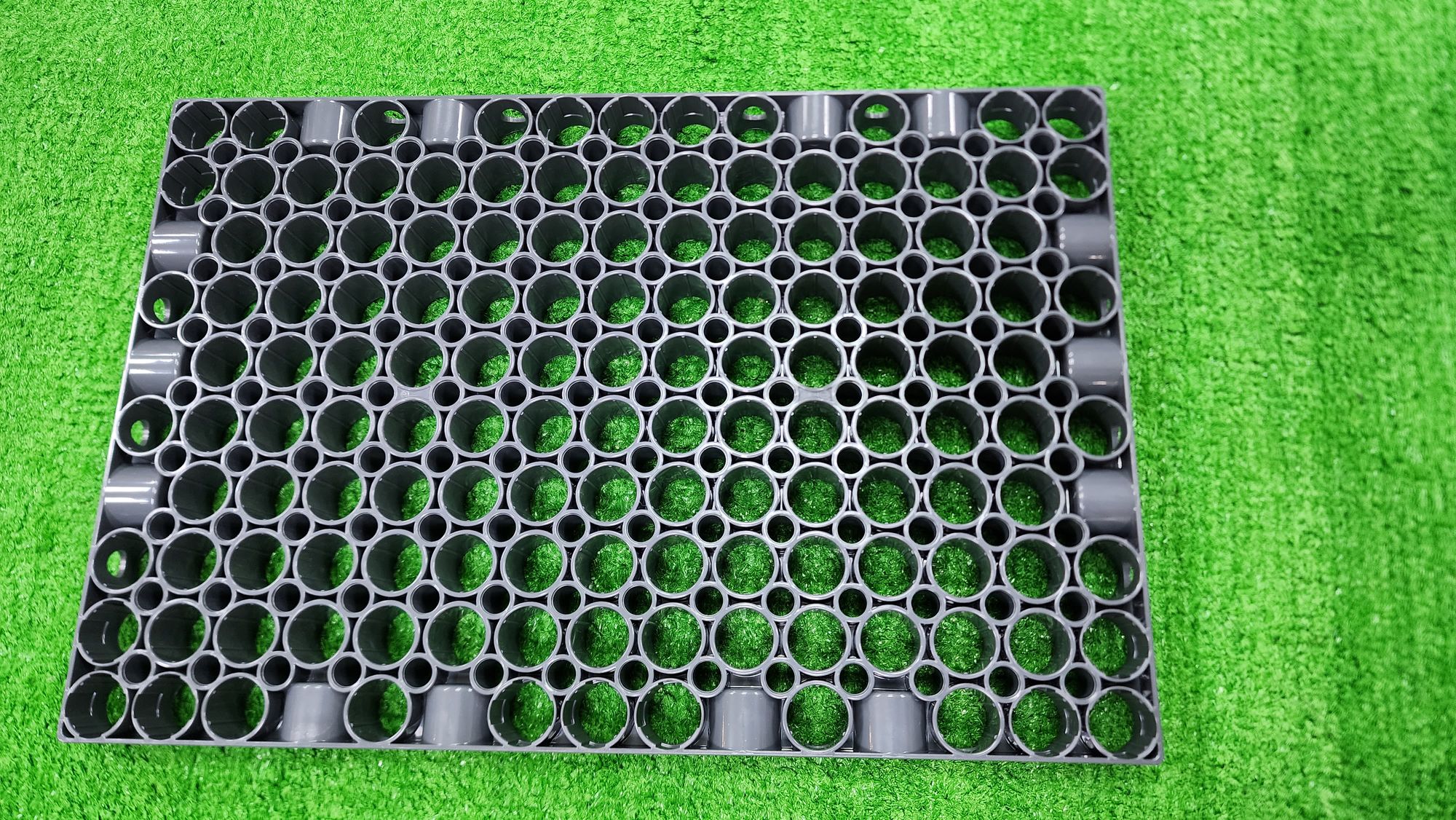
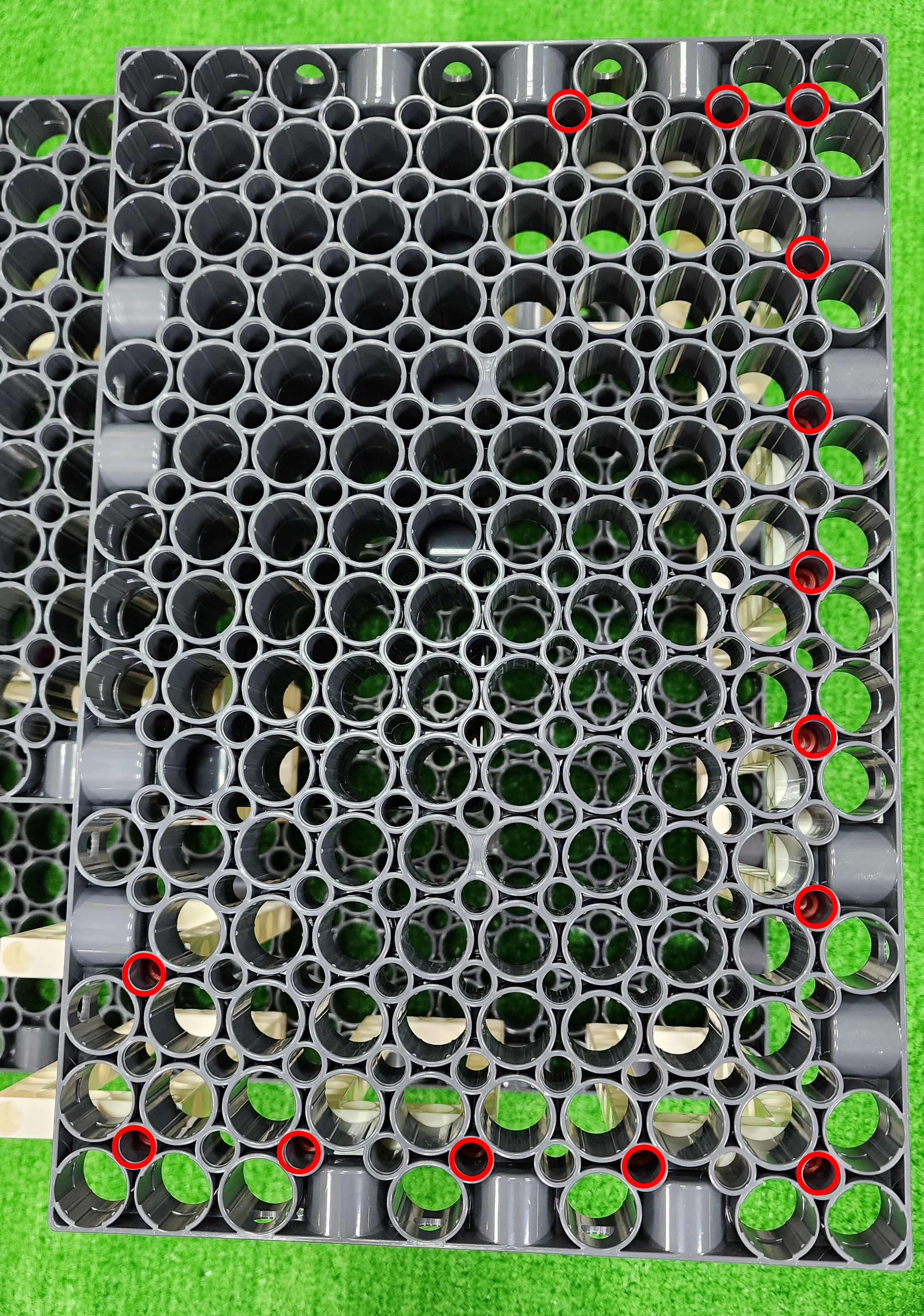
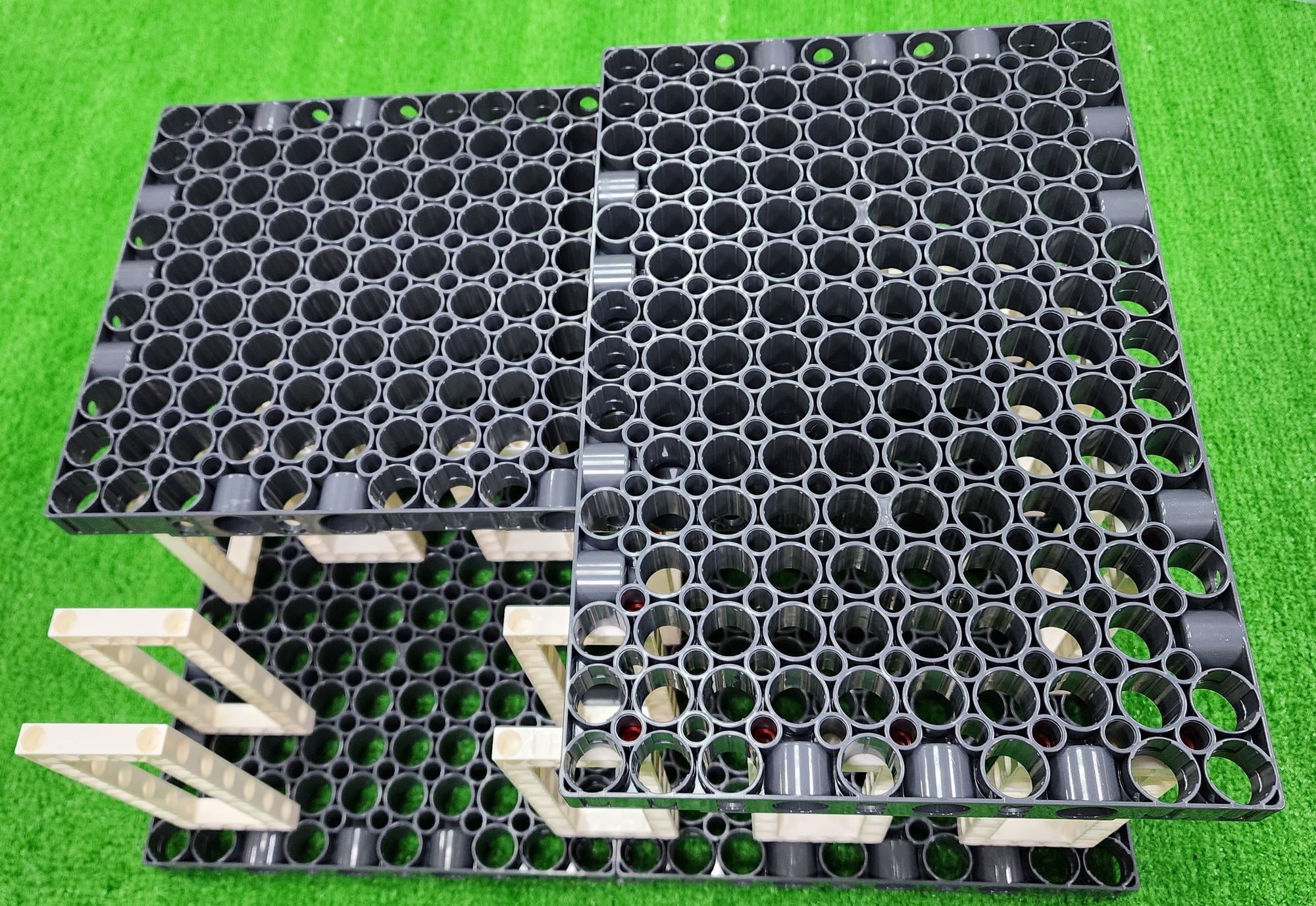
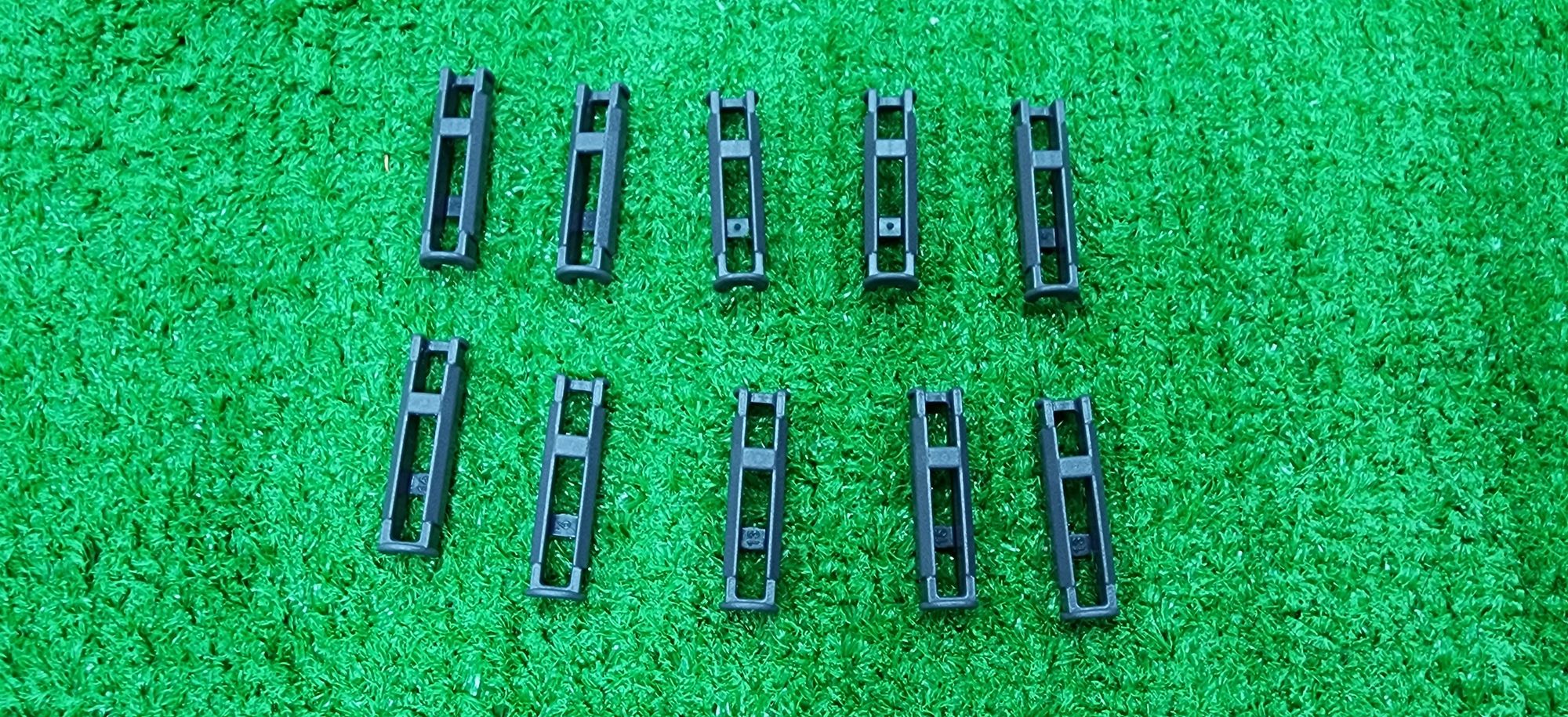
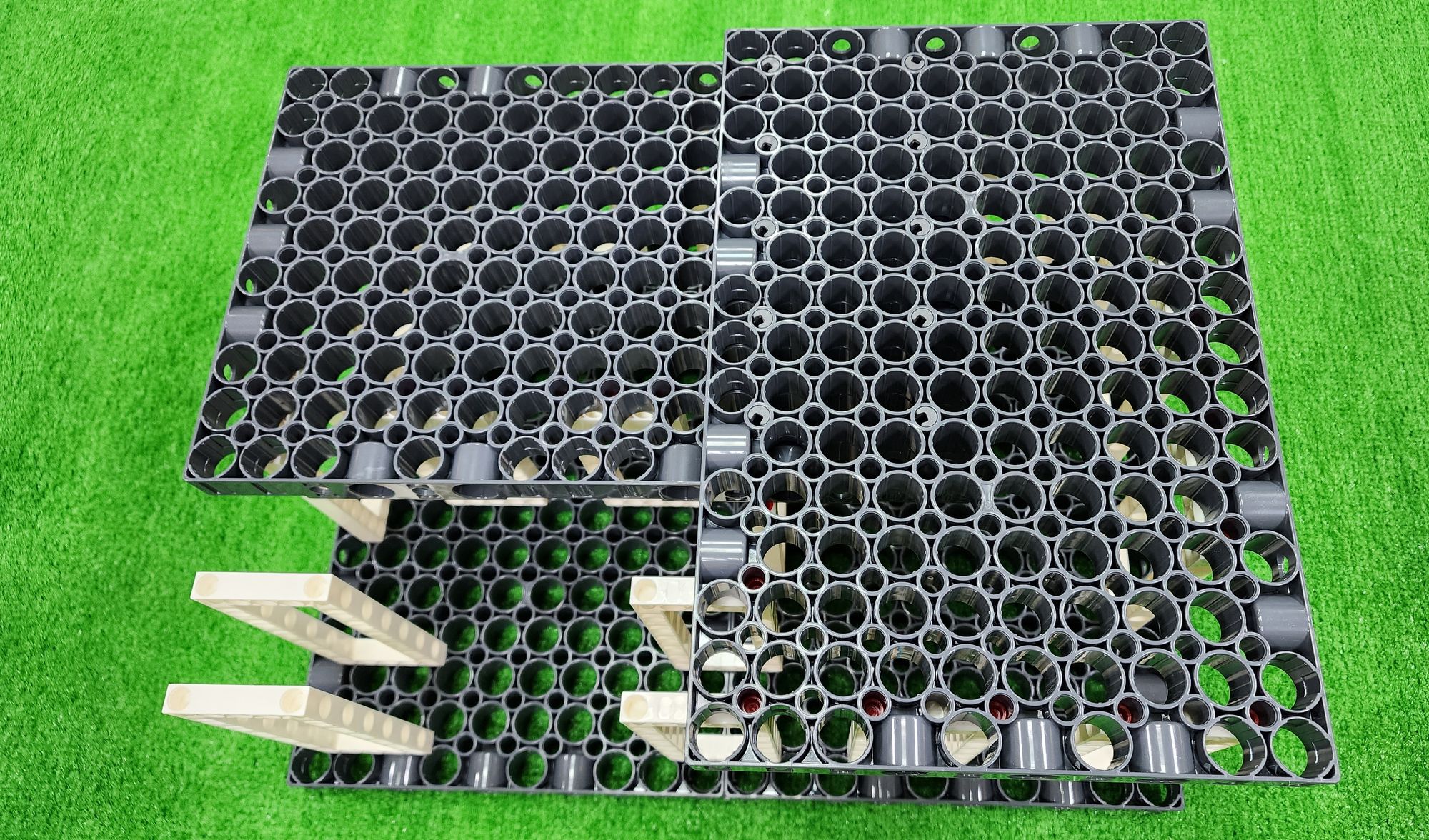
Step 1: We create the base of the claw machine. We'll need the C-JUMBO BASE GRID and the C-JUMBO BASE GRID CONNECTOR (Figure 1).
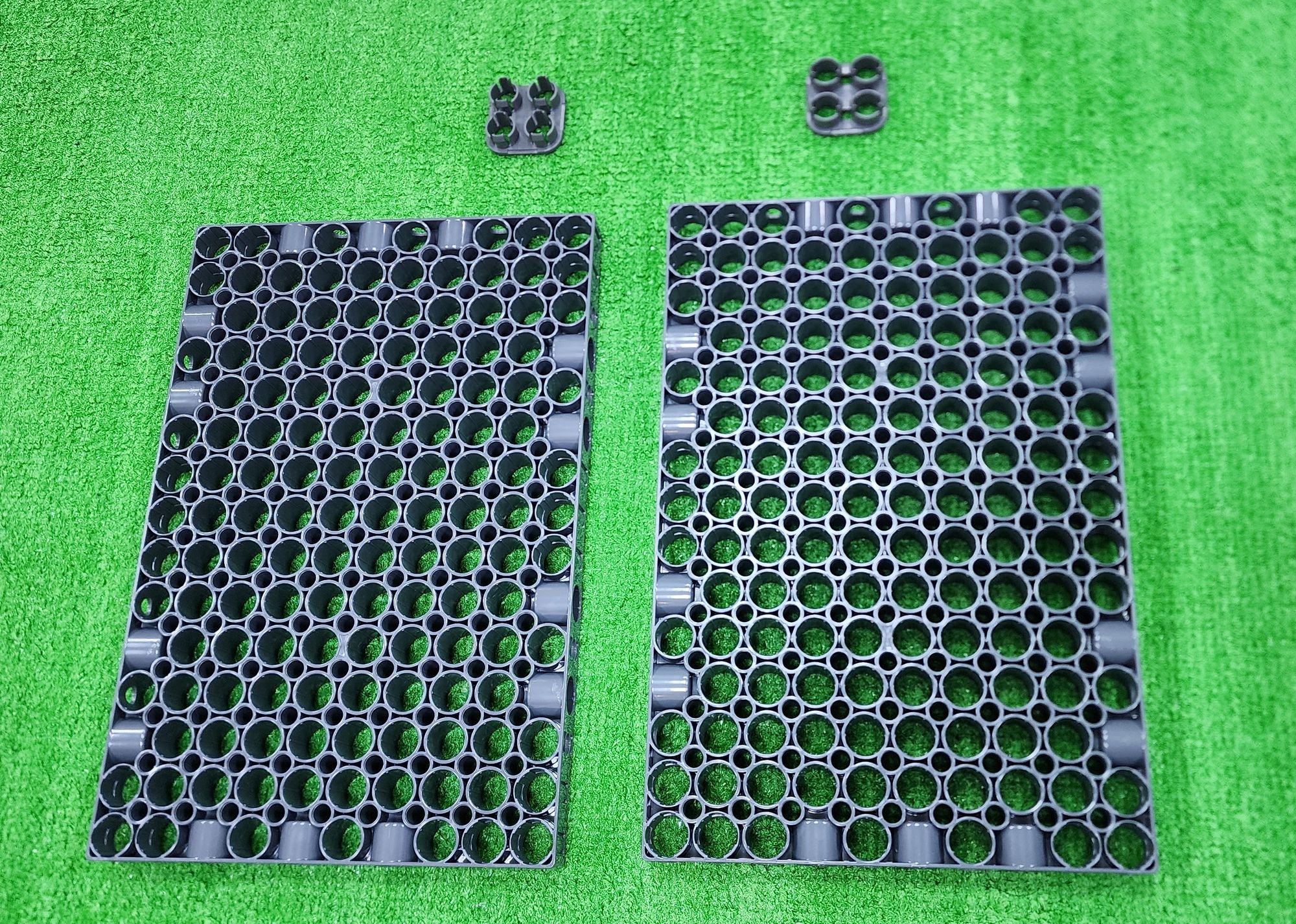
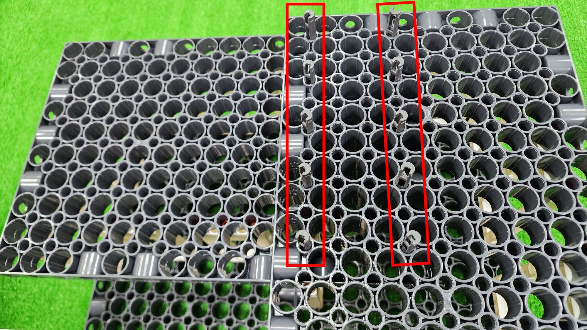
Join the two C-JUMBO BASE GRID together, and install the large base plate connector underneath the C-JUMBO BASE GRID CONNECTOR (see Figure 2, Figure 3).
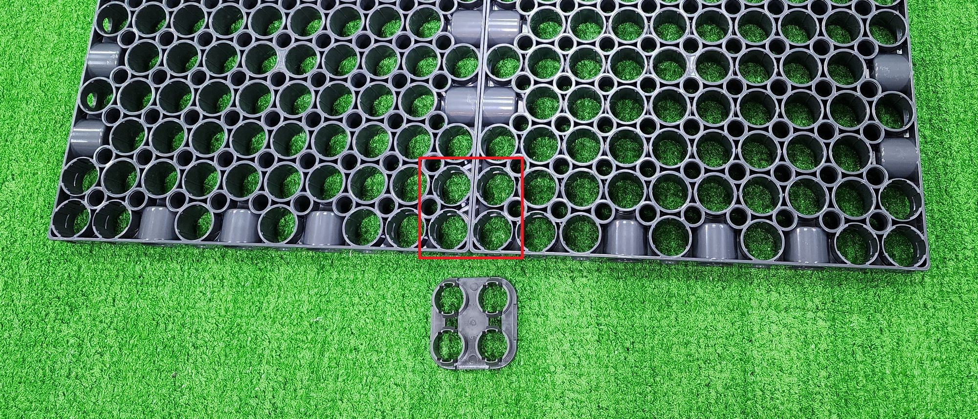
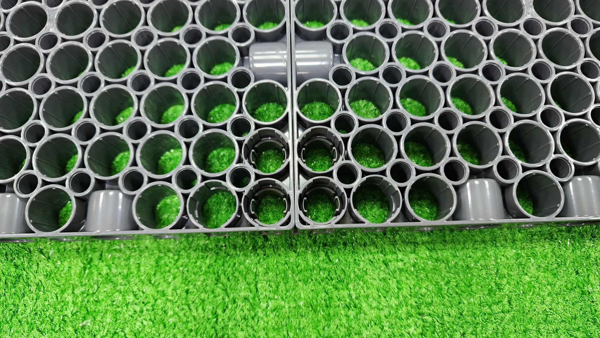
After installing both C-JUMBO BASE GRID CONNECTOR underneath the C-JUMBO BASE GRID, the base of the claw machine is complete (Figure 4).
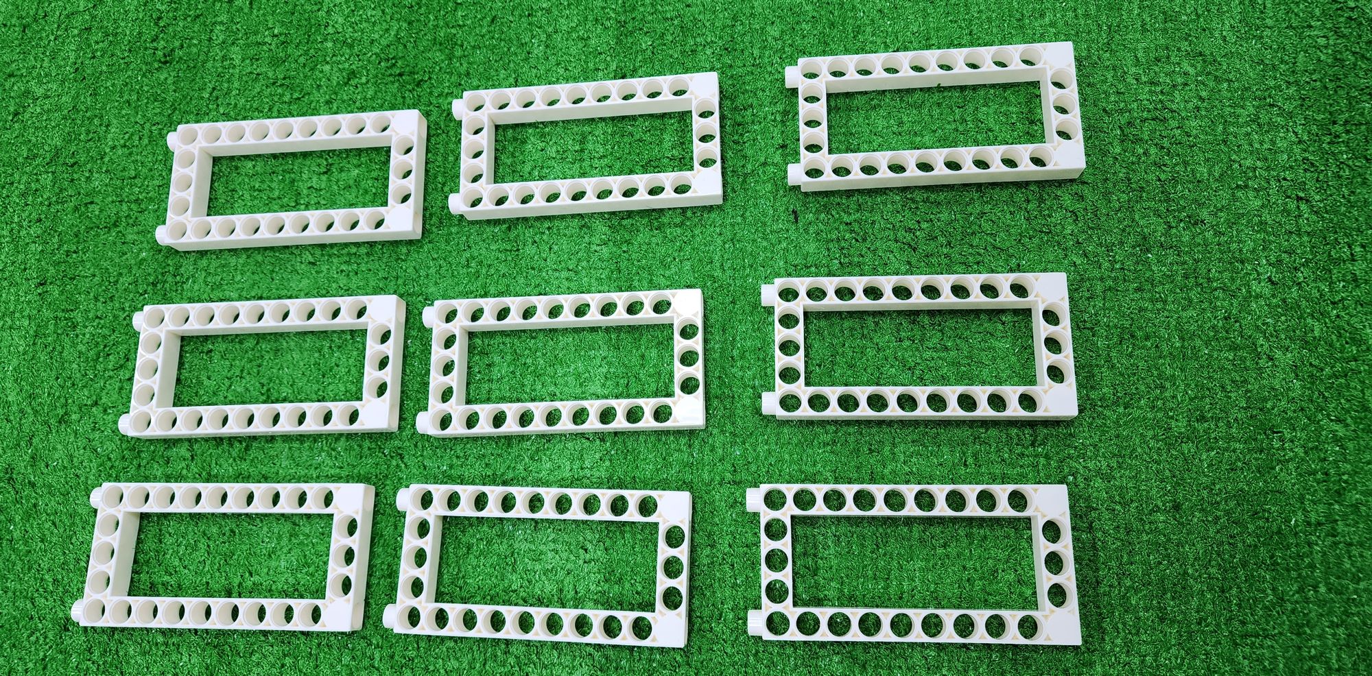
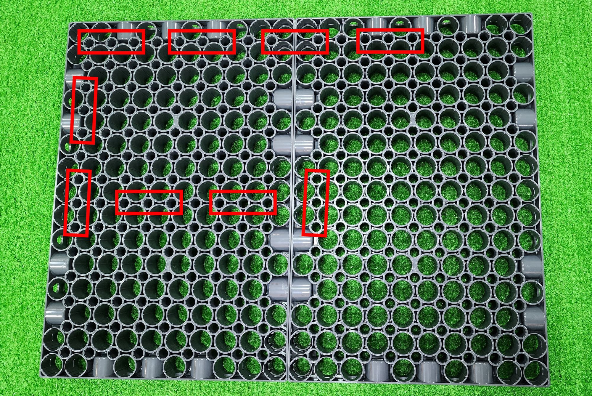
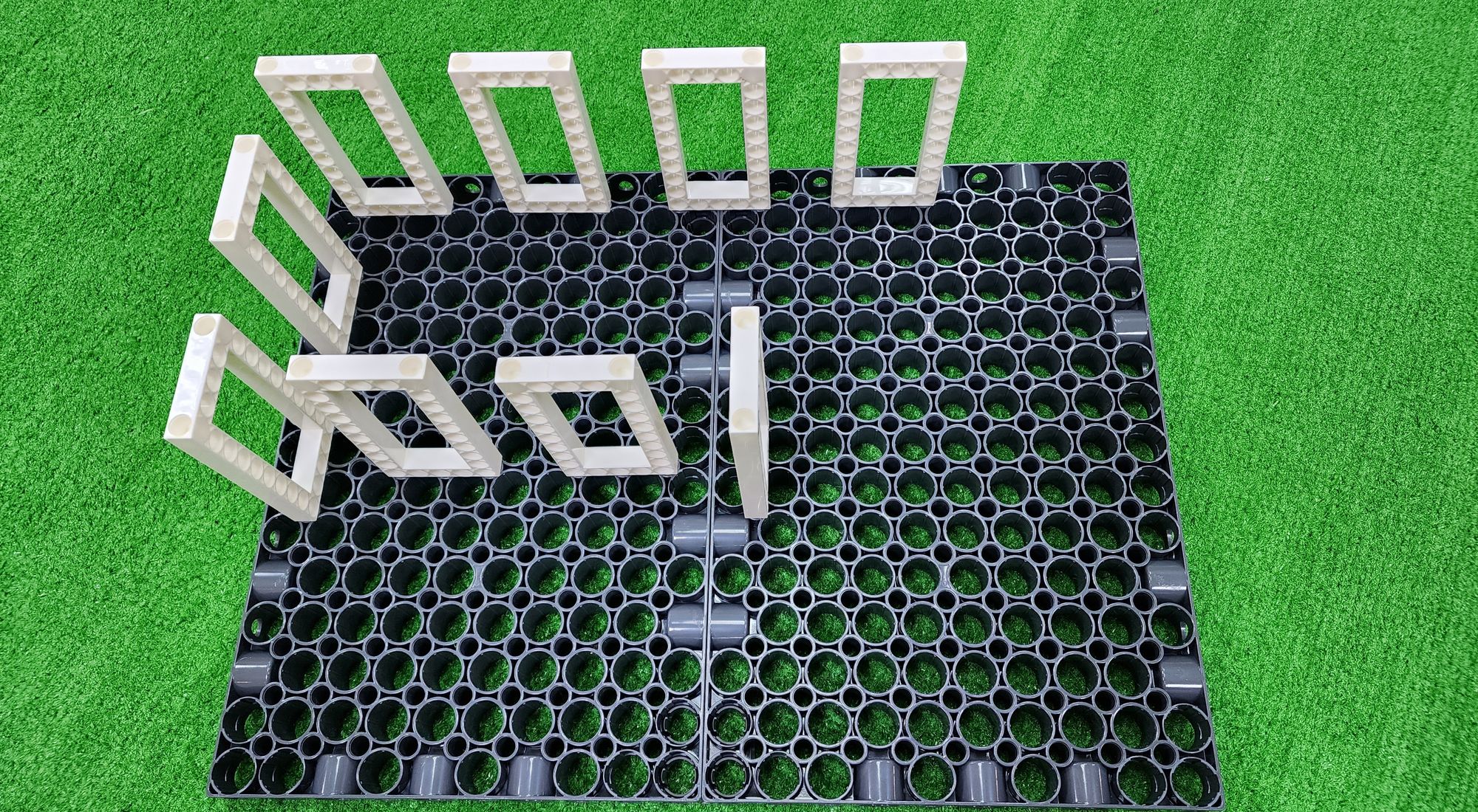
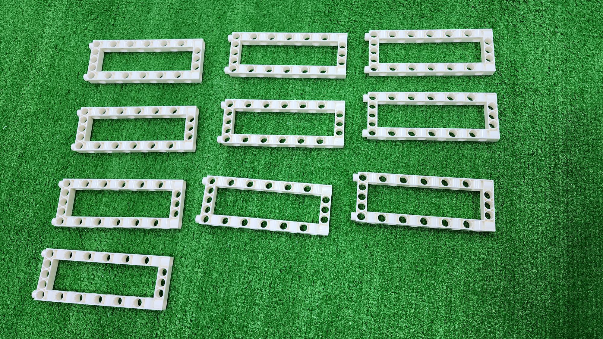
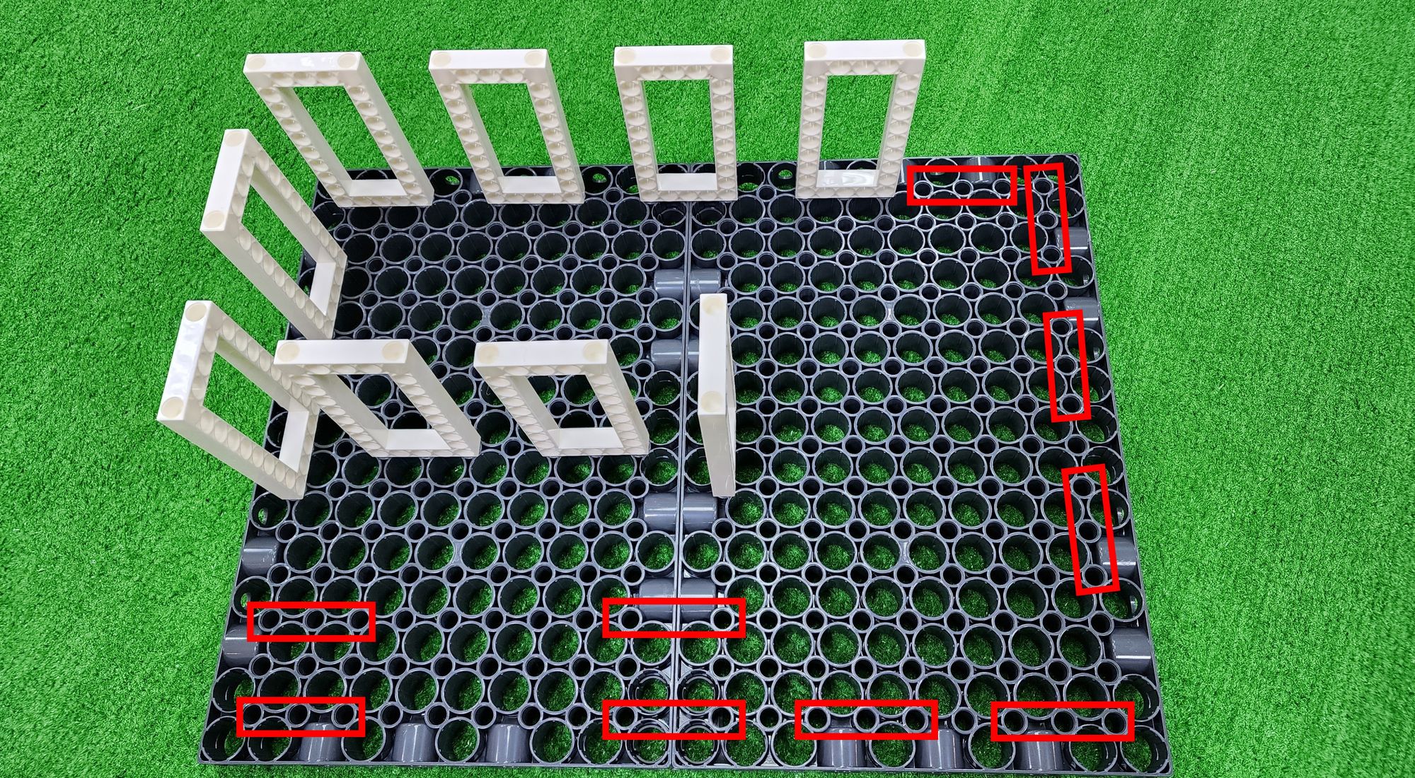
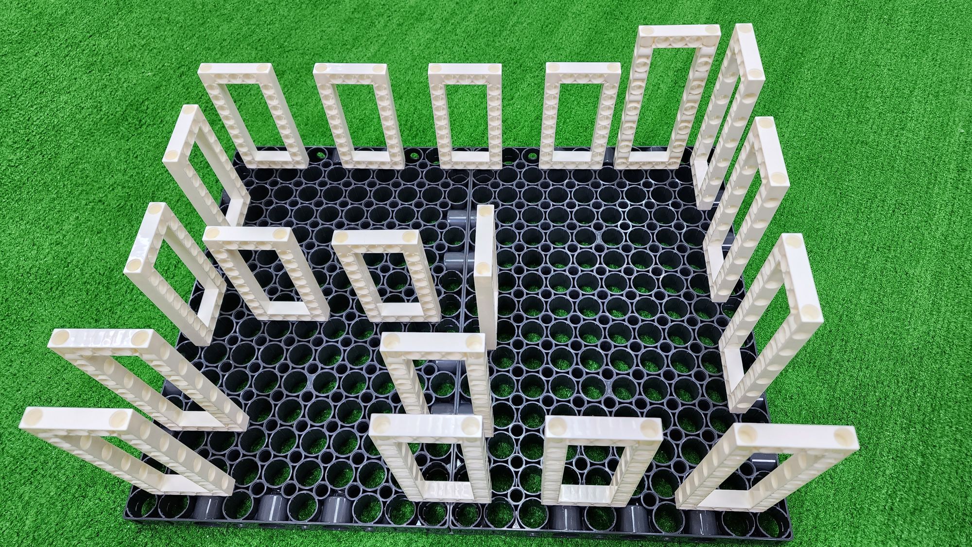
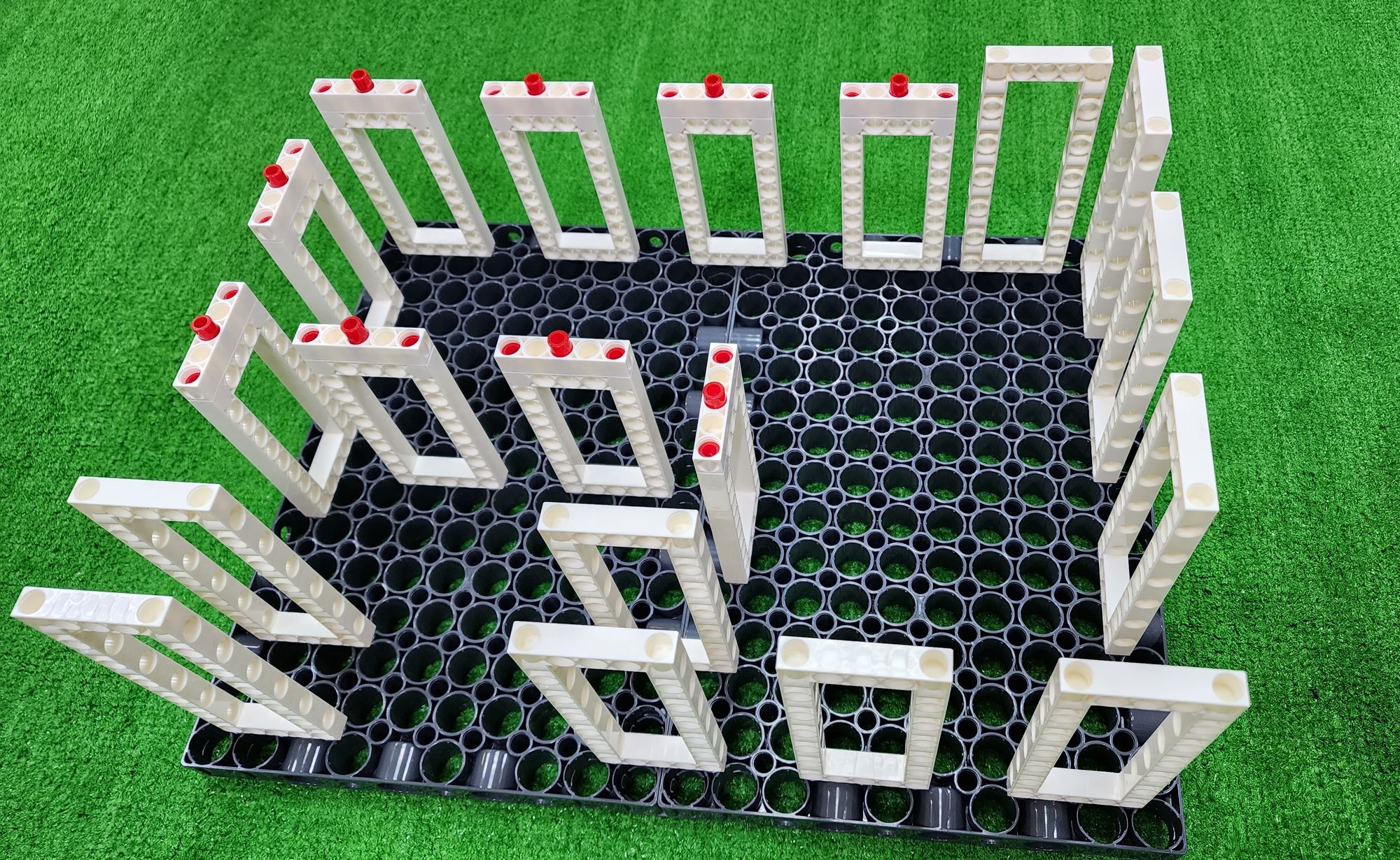
Step 2: We raise the structure of the claw machine to install the storage platform. We will need to use the C-5×10 FRAME (Figure 5). Install them according to the positions shown in the figure onto the top of the C-JUMBO BASE GRID(Figure 6, Figure 7).
Next, we need to use the C-5×13 DUAL FRAME (Figure 8). Similarly, install them according to the positions shown in the figure onto the top of the C-JUMBO BASE GRID (Figure 9, Figure 10).
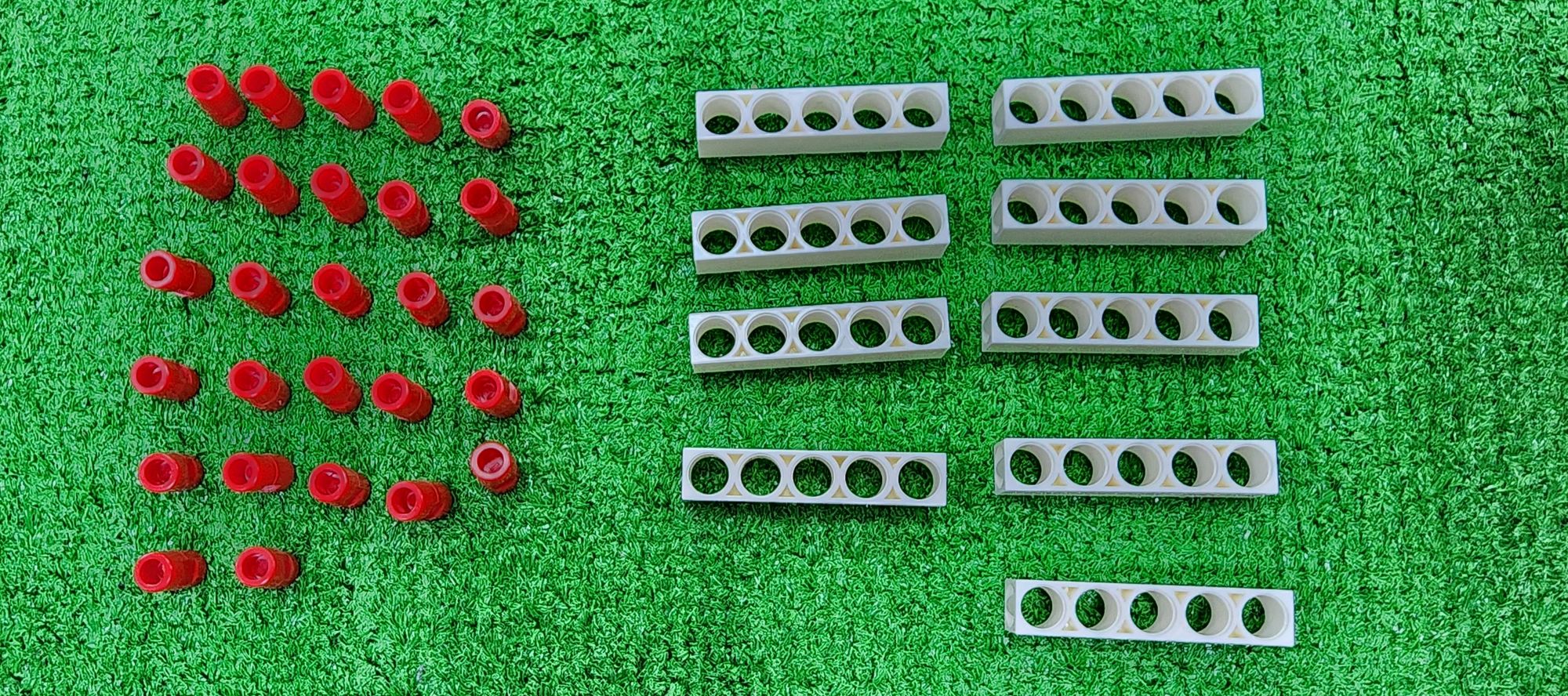
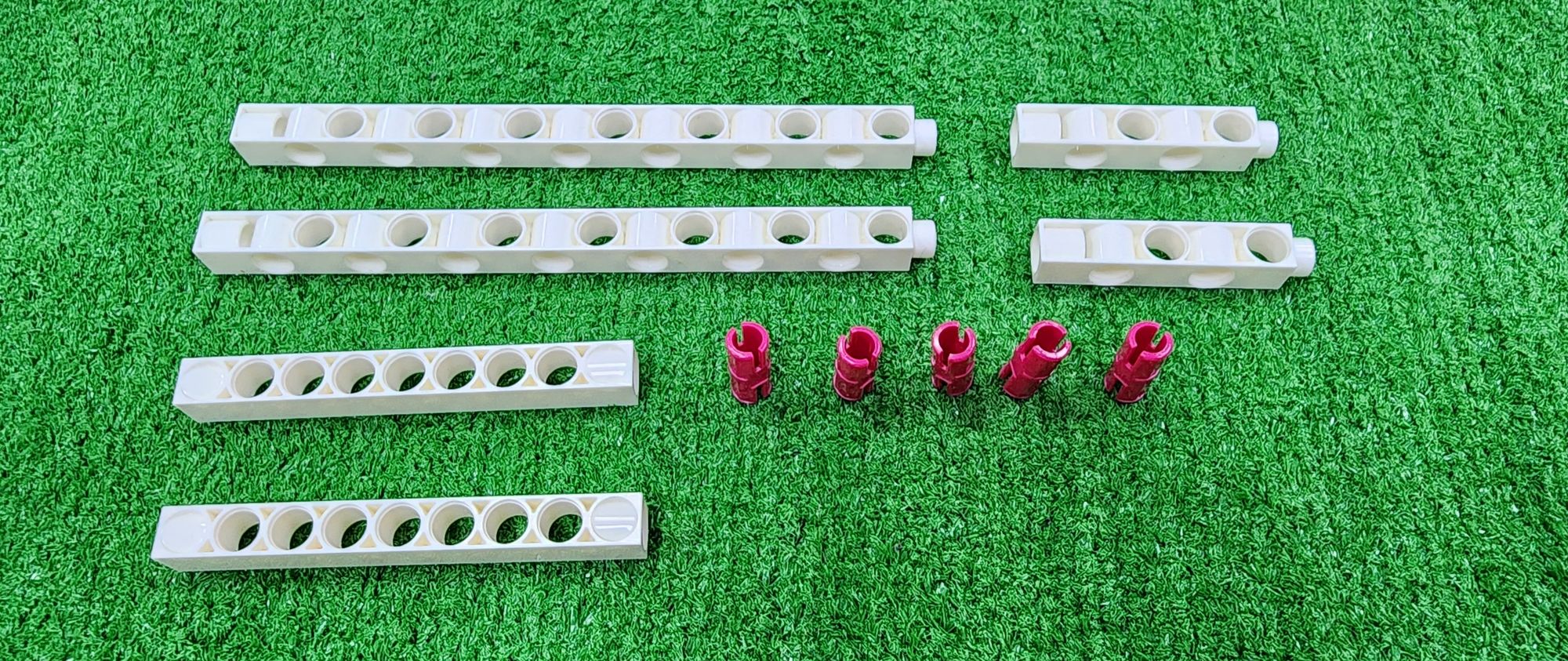
Step 3: We need to use the C-5 HOLE ROD and C-LONG PEG (Figure 11) to assemble them into nine parts (Figure 12), for connecting the storage platform.
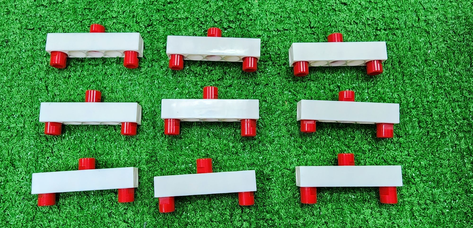
Next, install the completed nine parts onto the top of the C-5×10 FRAME (Figure 13).
Step 4: We now install the left side storage platform, for which we need to use a piece of C-JUMBO BASE GRID (Figure 14).
Place the C-JUMBO BASE GRID on top of the C-5×10 FRAME, and attach the C-LONG PEG underneath the C-JUMBO BASE GRID (Figure 15), completing the fixation of the left side storage platform (Figure 16).
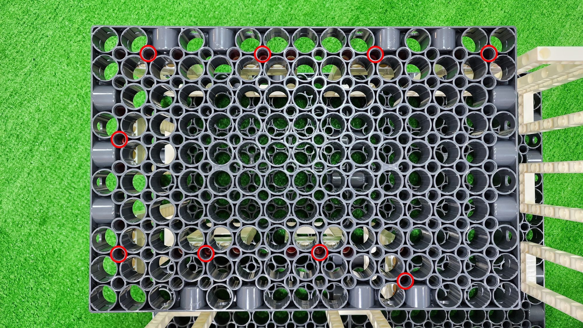
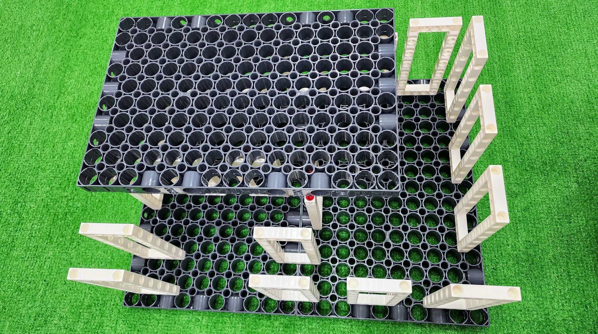
Step 5: We connect the right-side storage platform. This requires using fourteen C-LONG PEG (Figure 17). Place them on top of the C-5×13 DUAL FRAME (Figure 18).
Step 6: We install the right-side storage platform, using another piece of C-JUMBO BASE GRID (Figure 19).
Place the C-JUMBO BASE GRID on top of the C-5×13 DUAL FRAME, and attach the C-LONG PEG underneath the C-JUMBO BASE GRID (Figure 20) to fix the right-side storage platform (Figure 21).
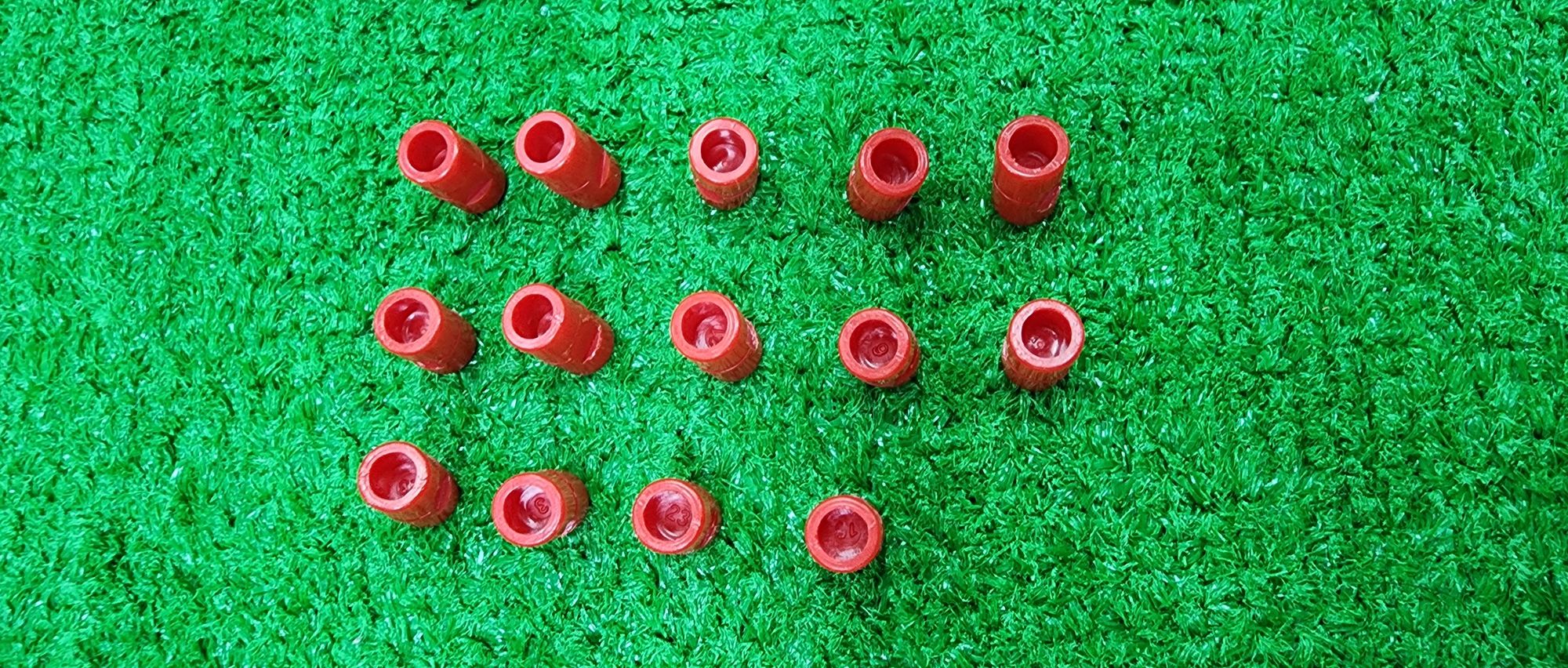
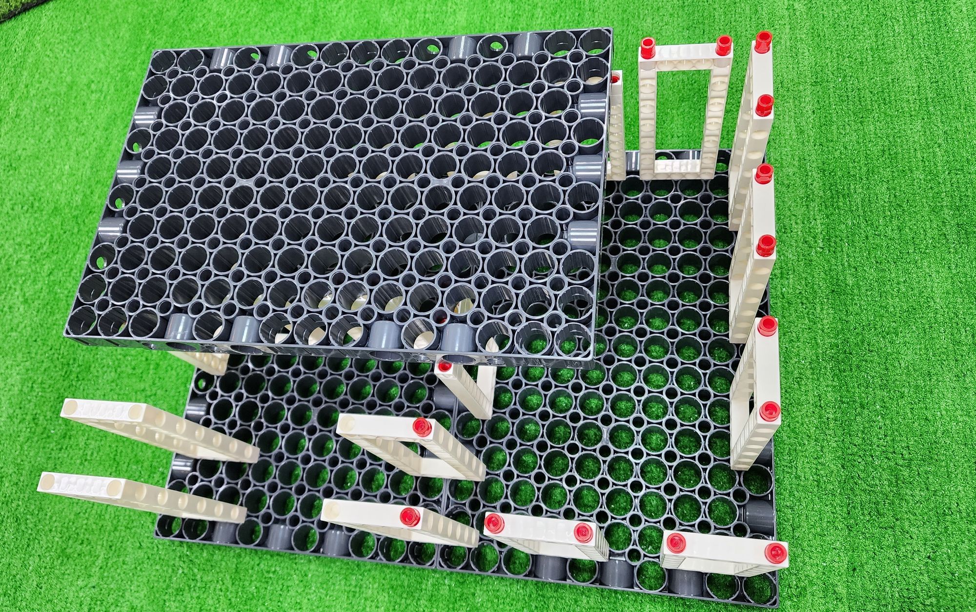
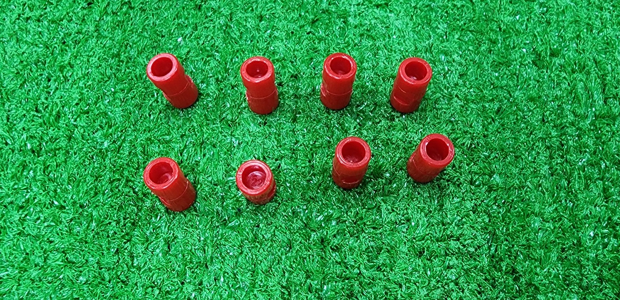
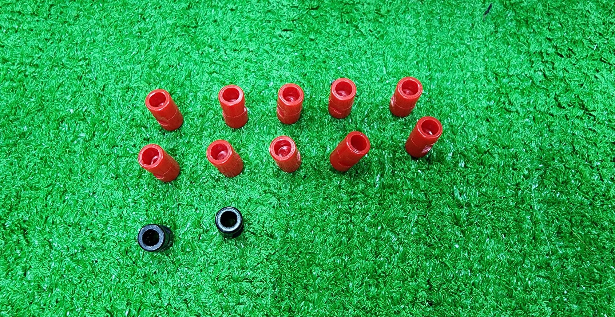
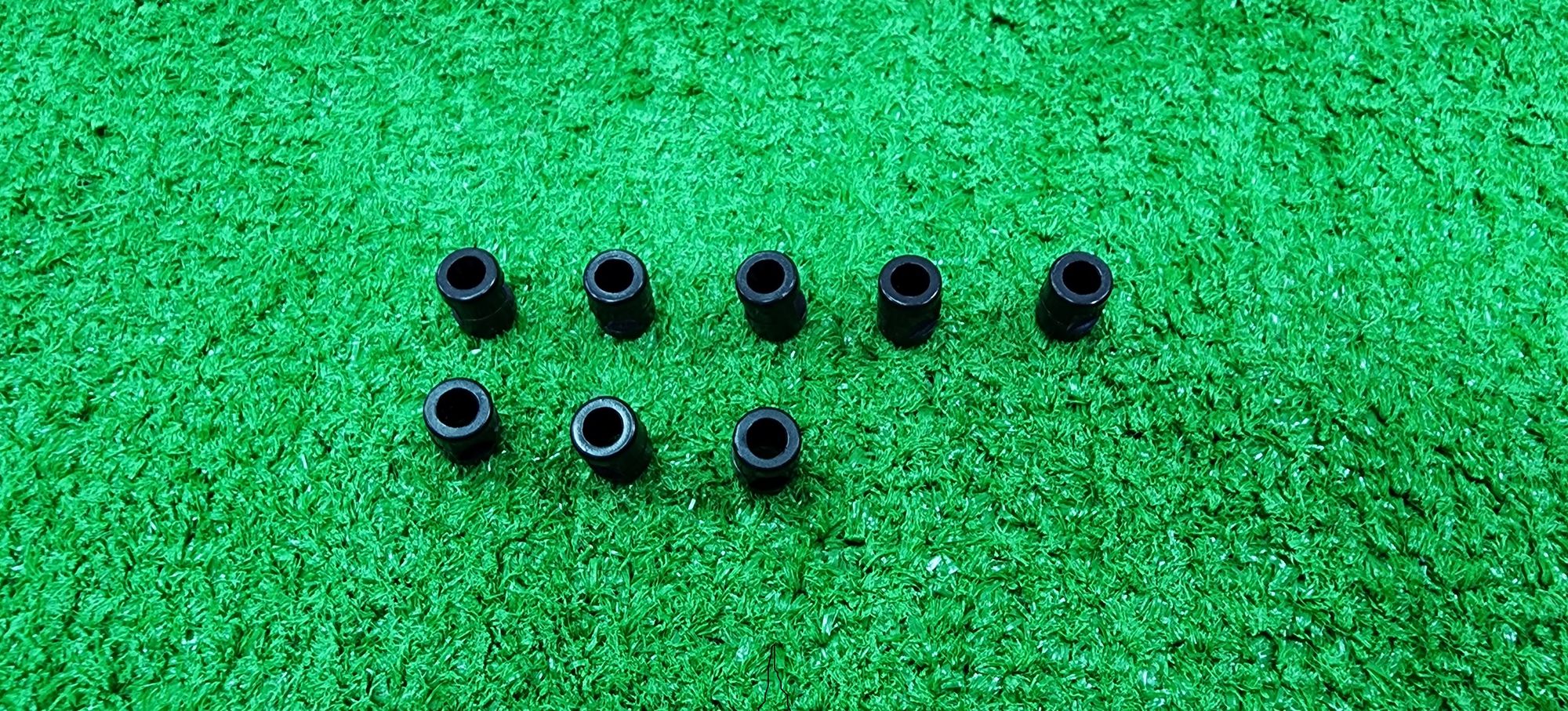
Step 7: We then secure the left and right storage platforms, requiring the use of a component called C-30mm STATIC CONNECTOR TUBE (7066-W10-A1S) (Figure 22).
Insert the C-30mm STATIC CONNECTOR TUBE into the C-JUMBO BASE GRID as shown (Figure 23), and fully push them down to secure the left and right storage platforms (Figure 24).
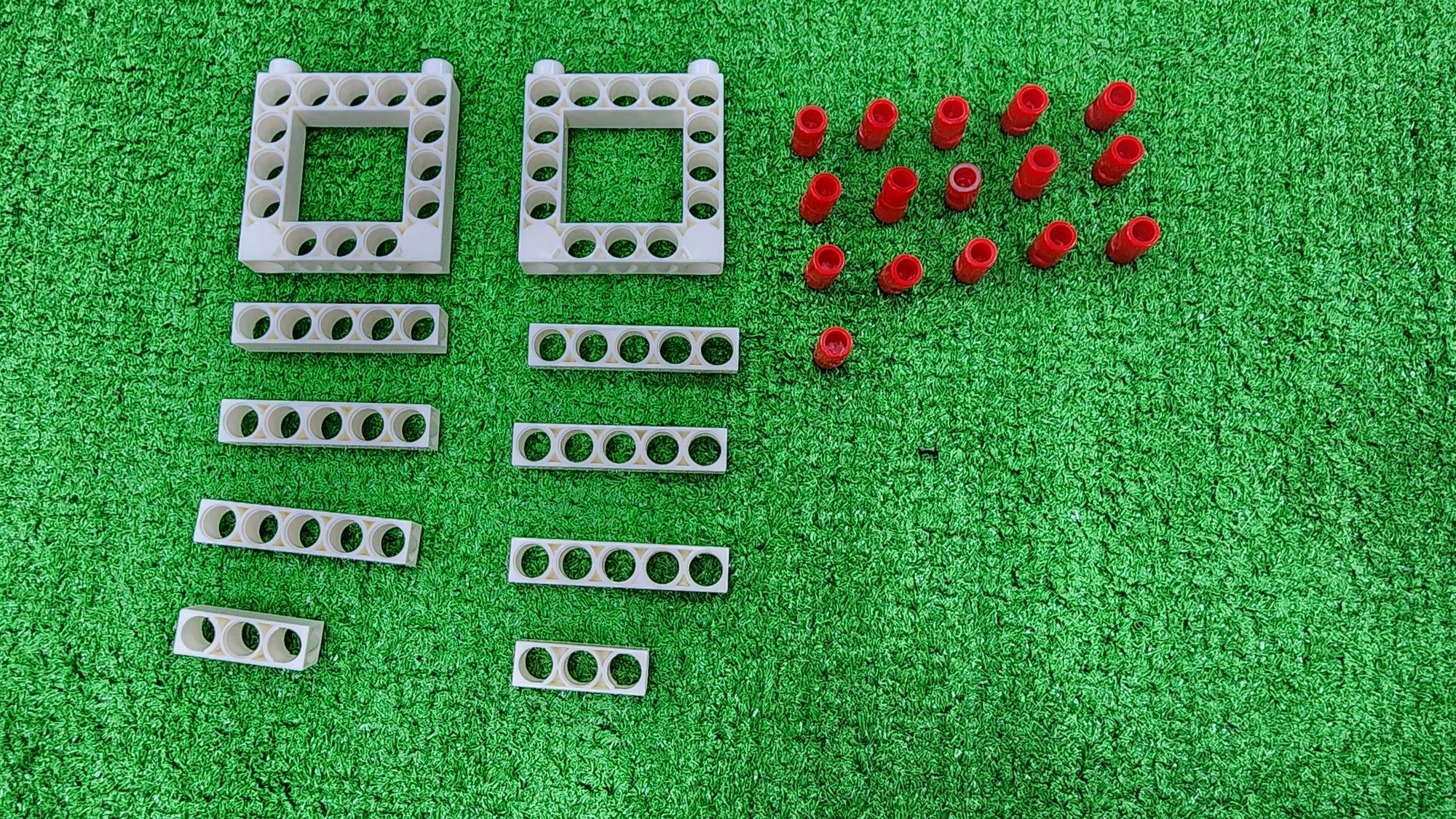
Step 8: We create the support base for the front left and rear left of the claw machine. We need to use C-5×5 FRAME, C-5 HOLE ROD, C-3 HOLE ROD, and C-LONG PEG (Figure 25).
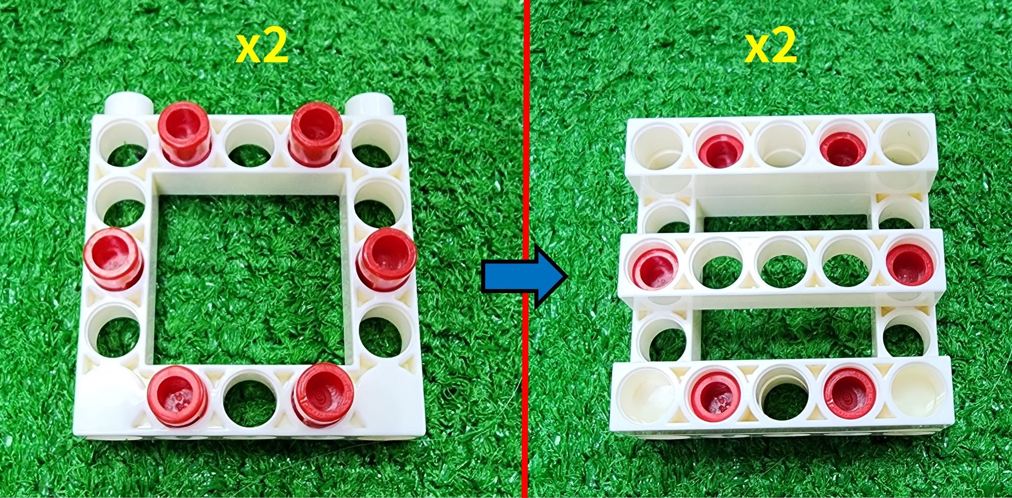
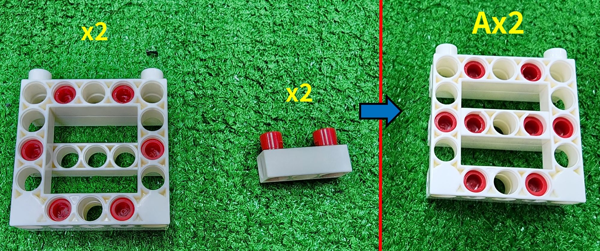
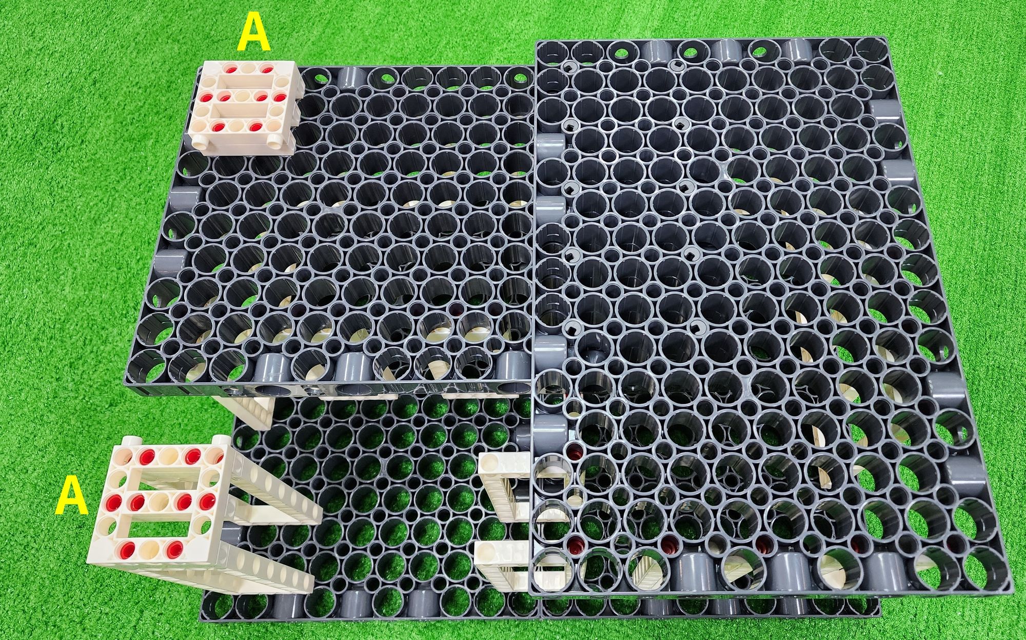
First, assemble the C-5×5 FRAME, C-5 HOLE ROD, and C-LONG PEG together (Figure 26). Then, flip it over and install the C-3 HOLE ROD, and C-LONG PEG. This completes the production of two part A (Figure 27).
To secure part A, we will use the C-LONG PEG (Figure 28). Install the C-LONG PEG respectively on the C-5×13 DUAL FRAME at the front left of the claw machine and on top of the C-JUMBO BASE GRID at the rear left (Figure 29).
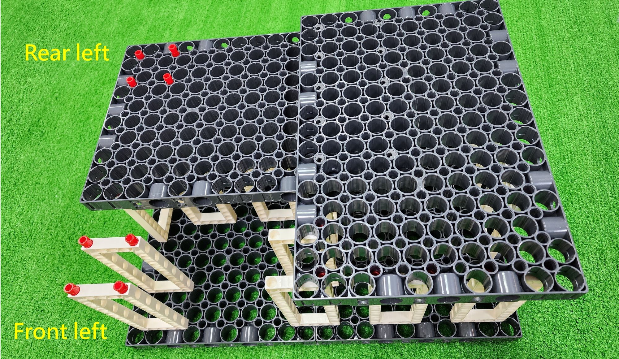
Finally, connect the two part A components with the C-LONG PEG, completing the fixation of the front left and rear left support base (Figure 30).
Step 9: We now install the brackets, for which we need to use C-LONG PEG, and B-SHORT PEG (Figure 31). Install them at the four corners of the claw machine (Figure 32).
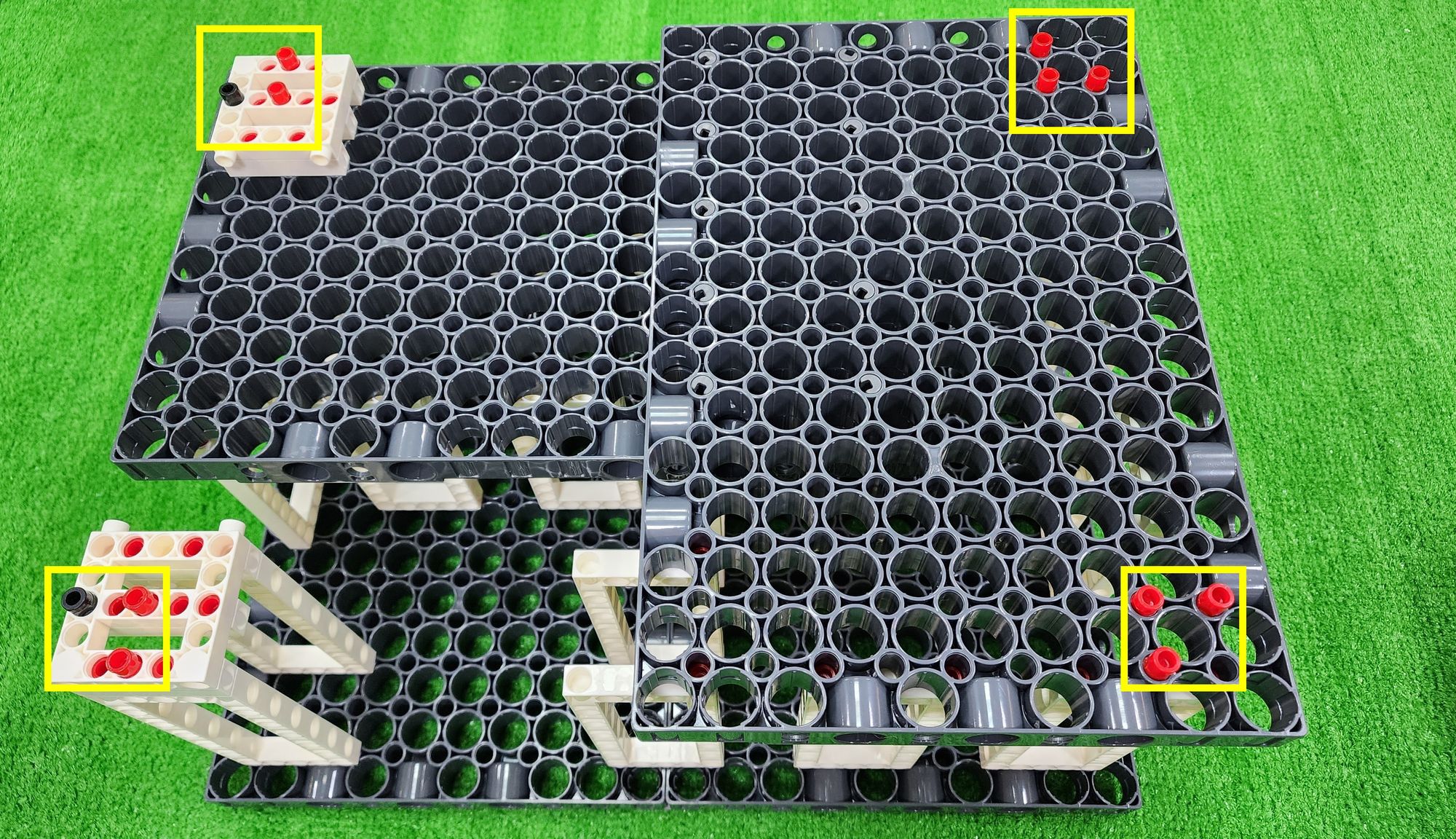
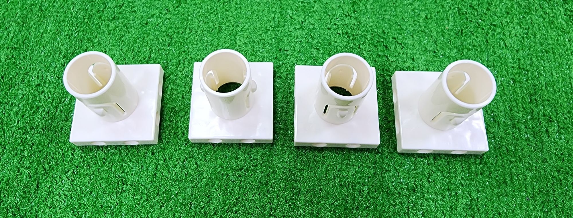
For the brackets, we'll need to use C-TUBE ADAPTER (Figure 33). First, install the C-TUBE ADAPTER at the four corners of the claw machine respectively, and then connect them with the C-LONG PEG, and B-SHORT PEG (Figure 34).
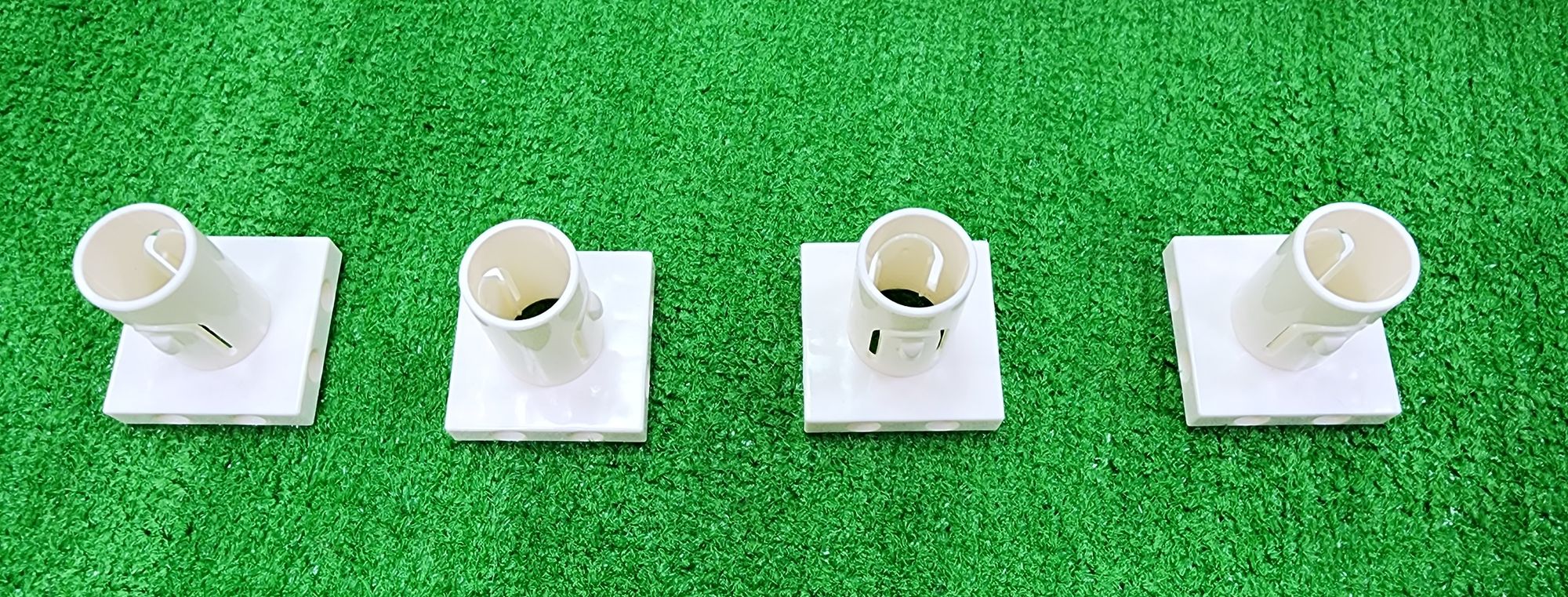
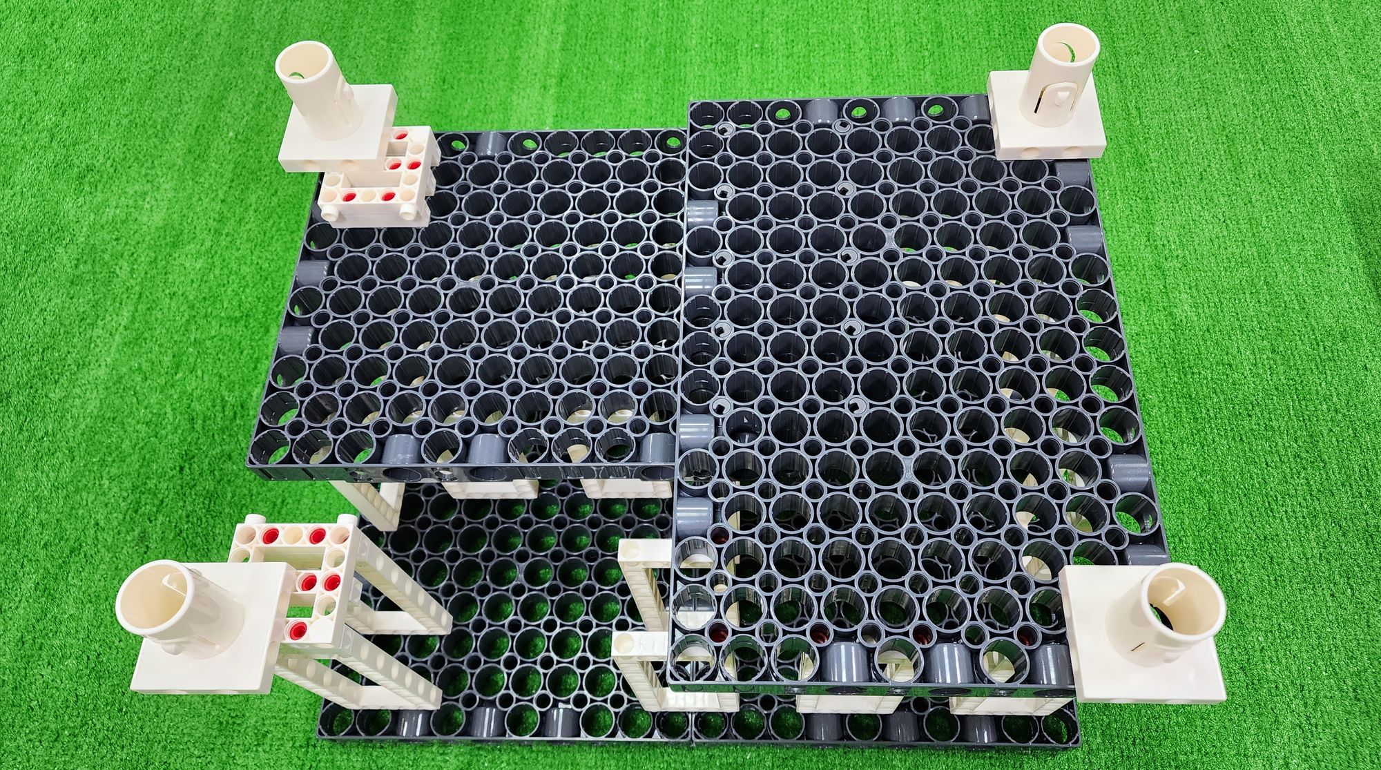
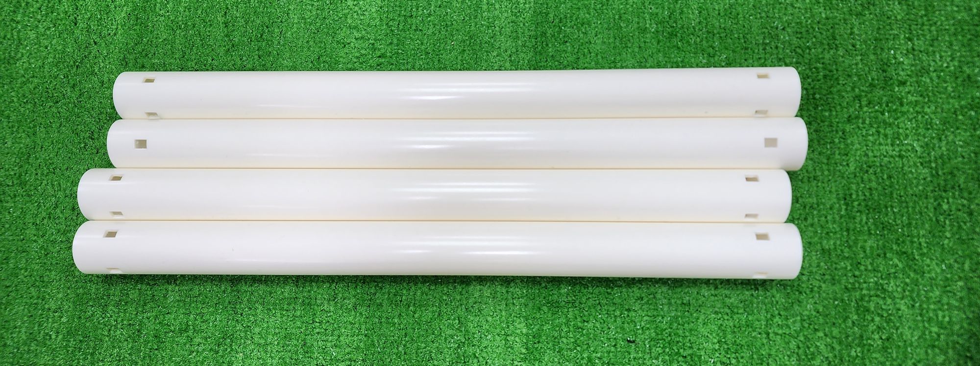
Next, we'll use the E-410mm TUBE (Figure 35). Connect the E-410mm TUBE with the C-TUBE ADAPTER to extend the length of the brackets (Figure 36).
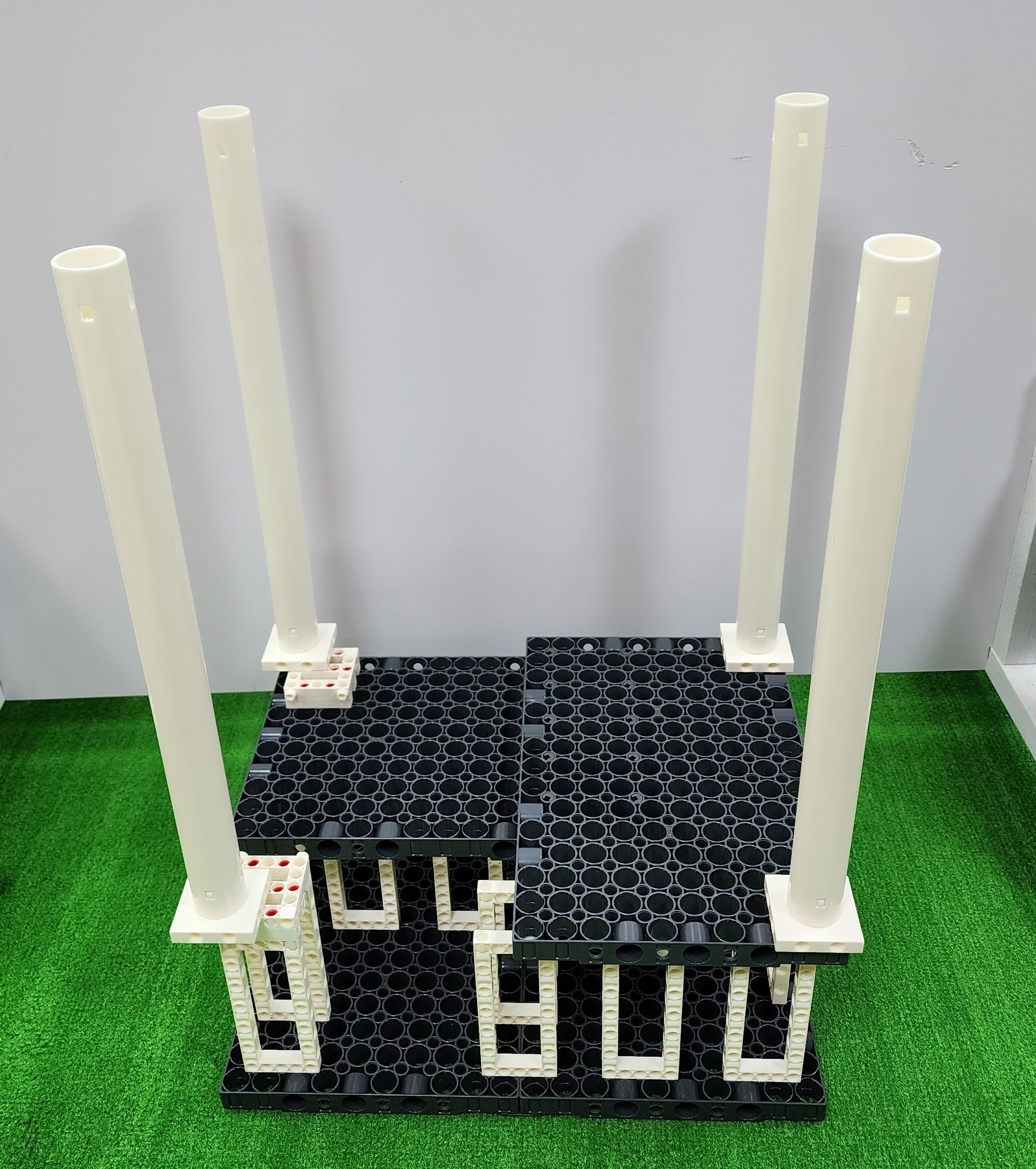
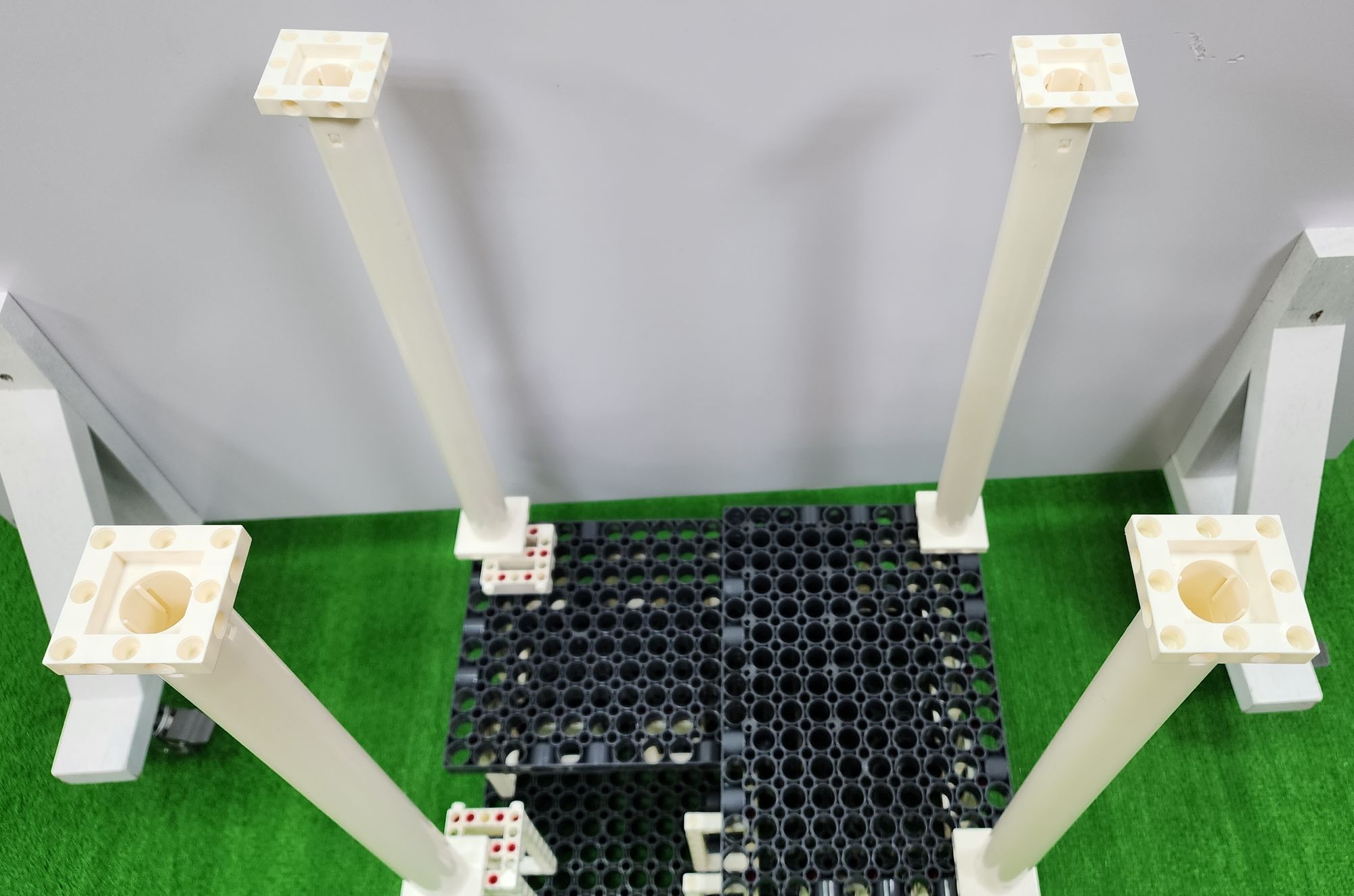
Finally, we'll again use the C-TUBE ADAPTER (Figure 37). Install the C-TUBE ADAPTER on top of each of the four E-410mm TUBE to complete the fabrication of the brackets (Figure 38).
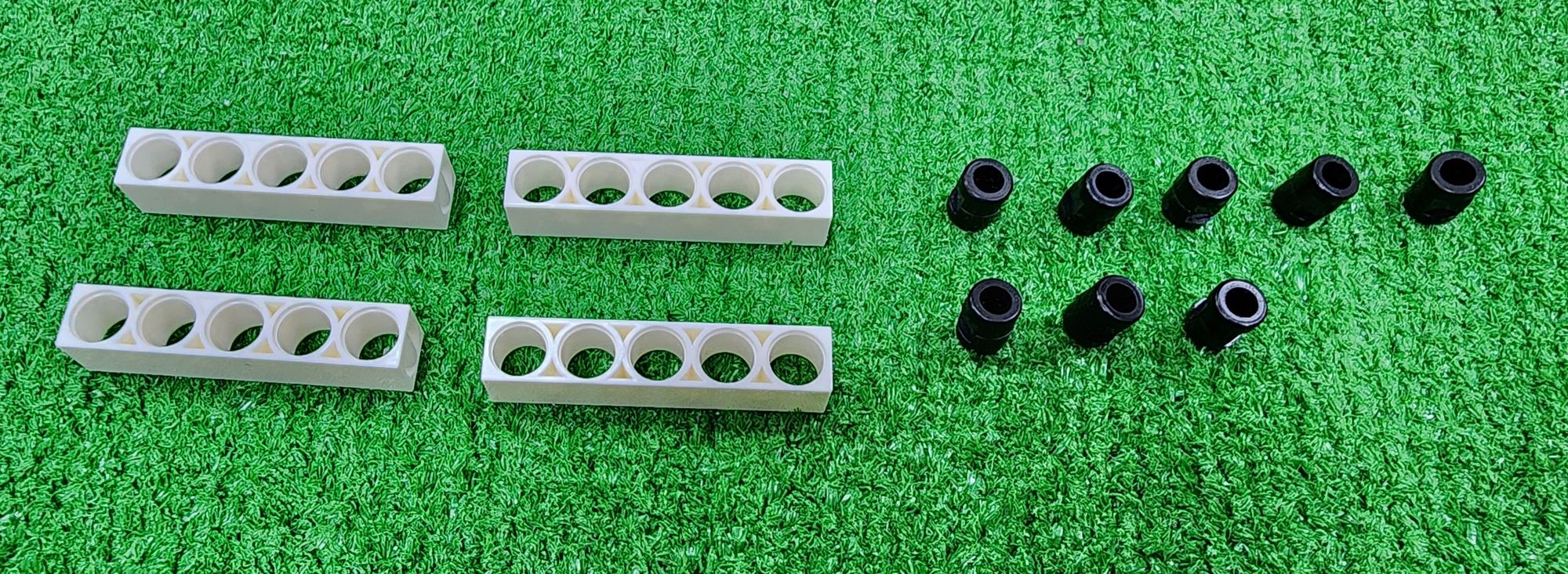
Step 10: We can then add some design elements above the brackets to secure the tracks. First, we need to use C-5 HOLE ROD and B-SHORT PEG (Figure 39). Attach them above the C-TUBE ADAPTER (Figure 40, Figure 41).
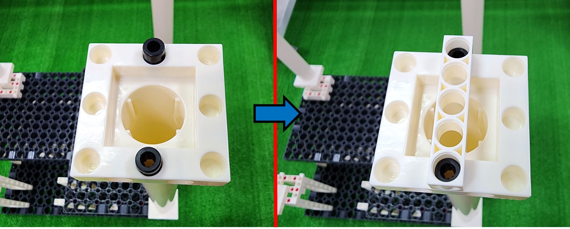
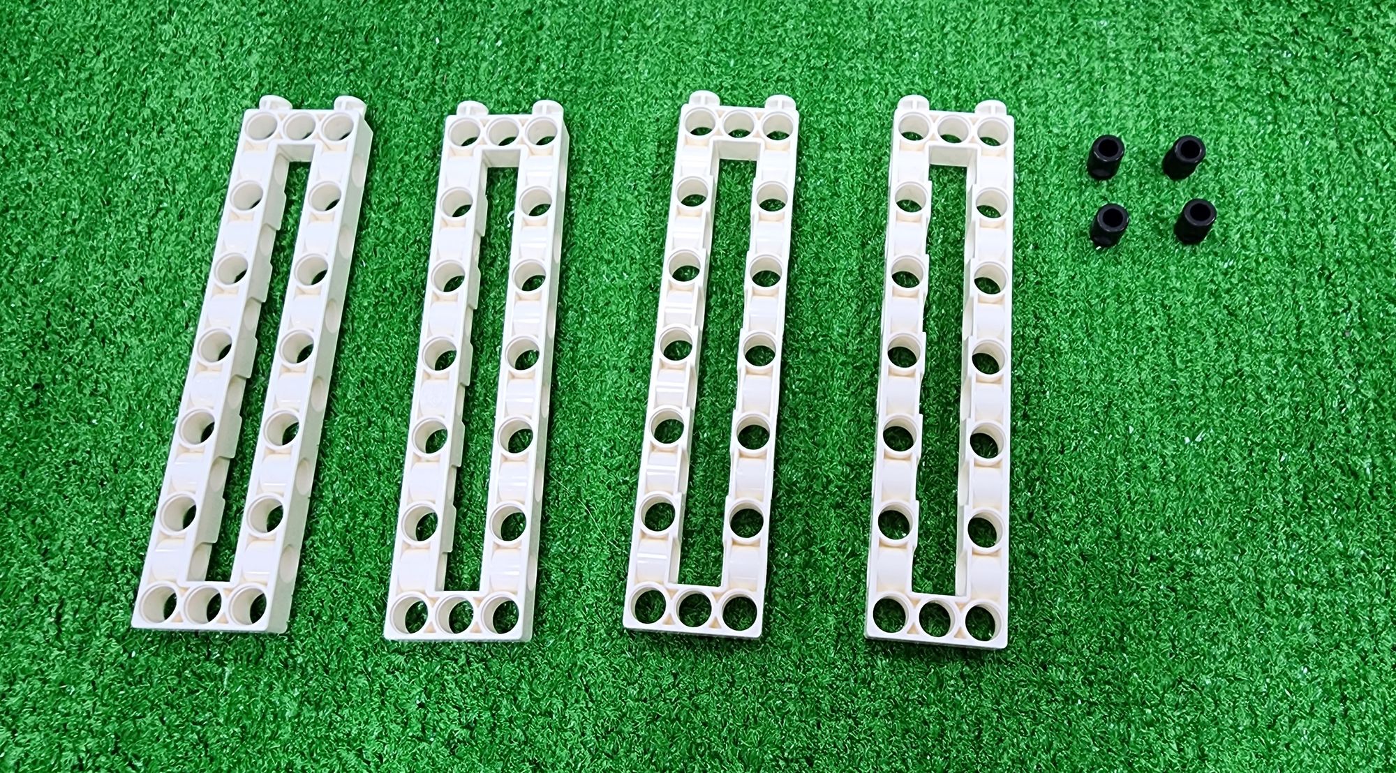
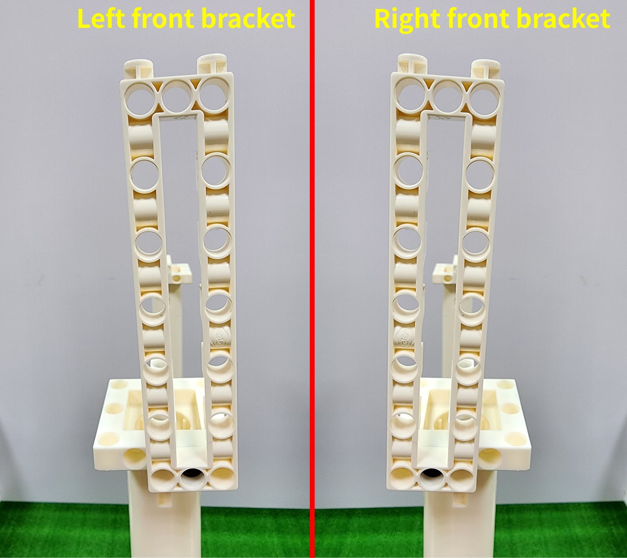
Next, we'll need to use the C-3x13 DUAL FRAME (7406-W10-A1W) and B-SHORT PEG (Figure 42).
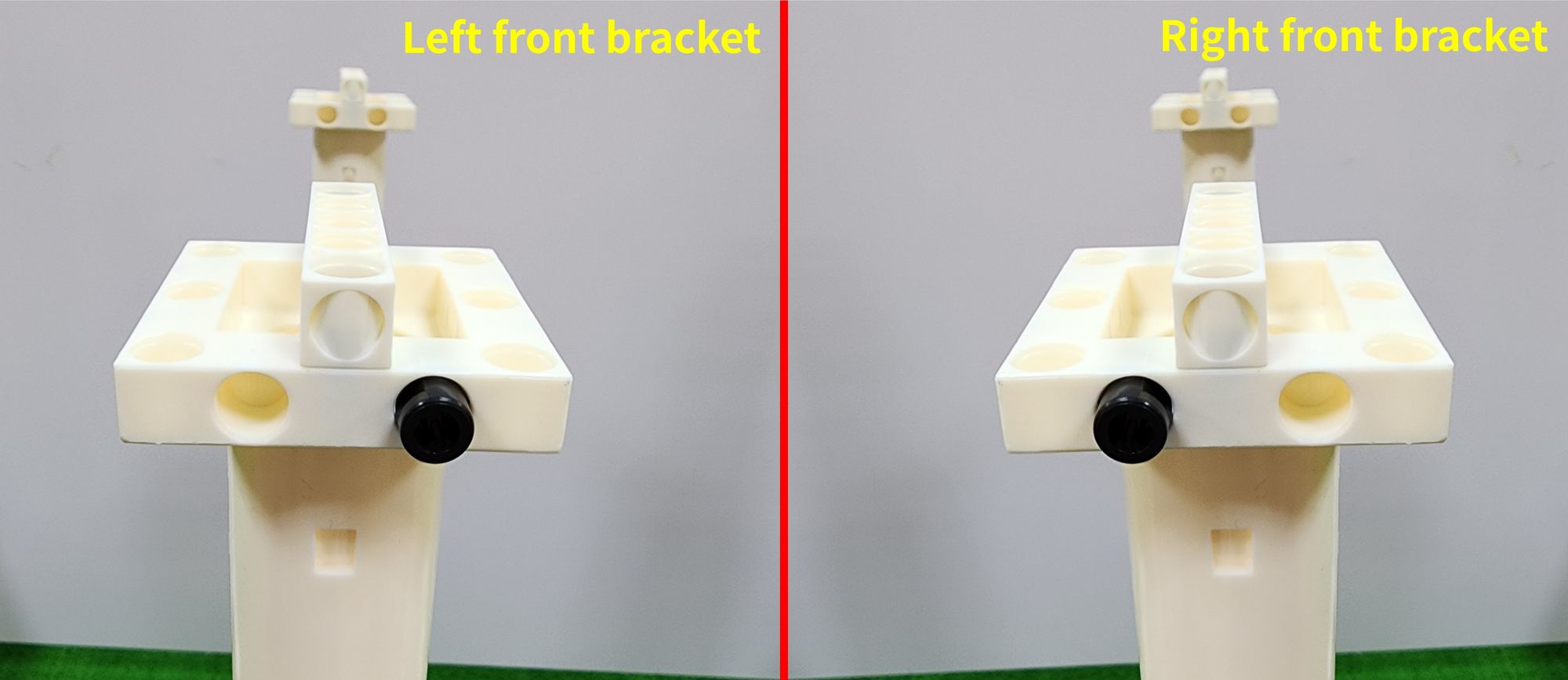
First, install the B-SHORT PEG and the C-3x13 DUAL FRAME onto the C-TUBE ADAPTER. It's important to note the position of the B-SHORT PEG here. The B-SHORT PEG on the left front bracket should be positioned towards the right, while the one on the right front bracket should be positioned towards the left. Both positions should be closer to the inner side of the centerline and symmetrical to each other (Figure 43). Once you've confirmed the correct positions of the B-SHORT PEG, you can then install the C-3x13 DUAL FRAME (Figure 44).
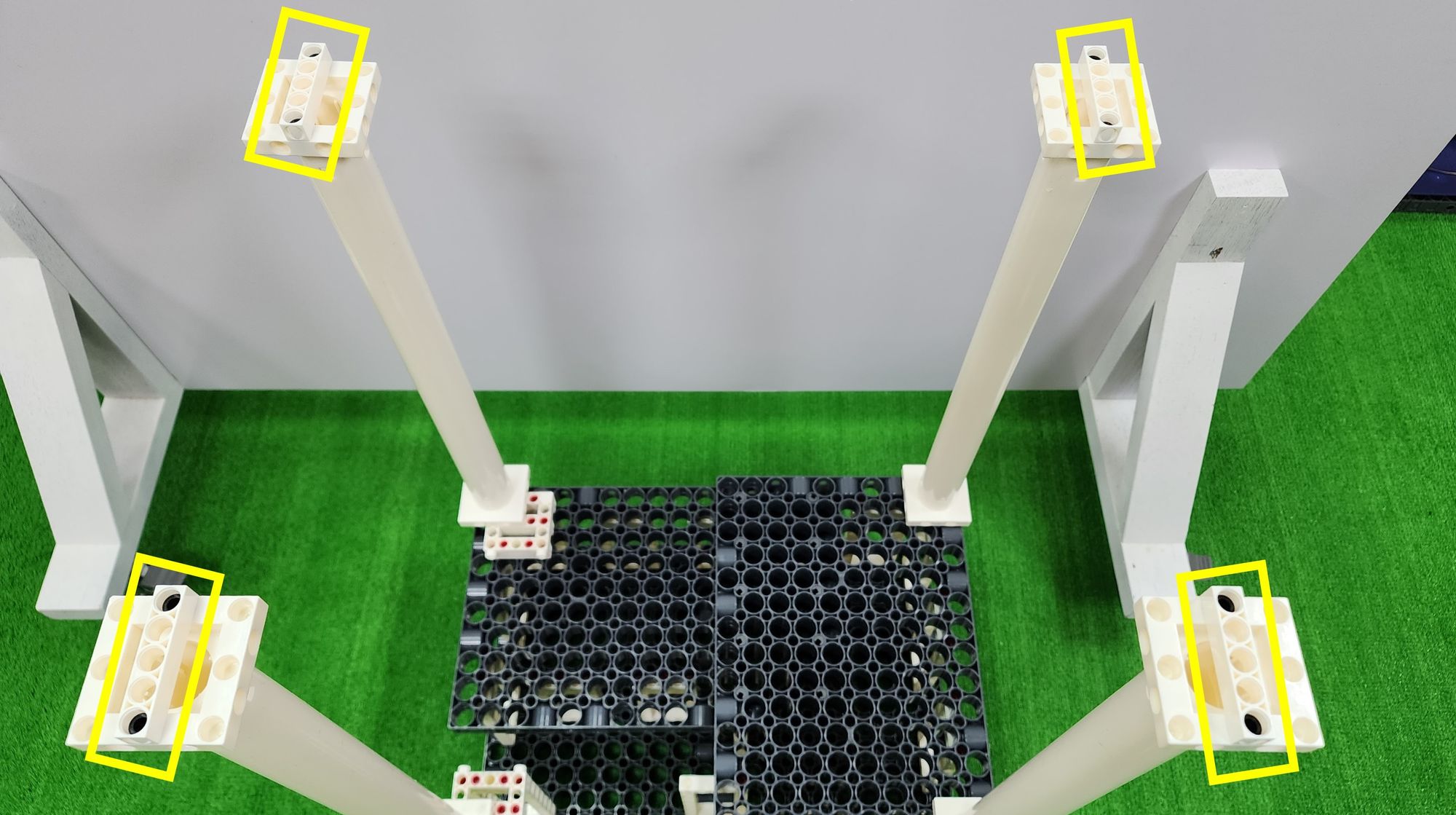
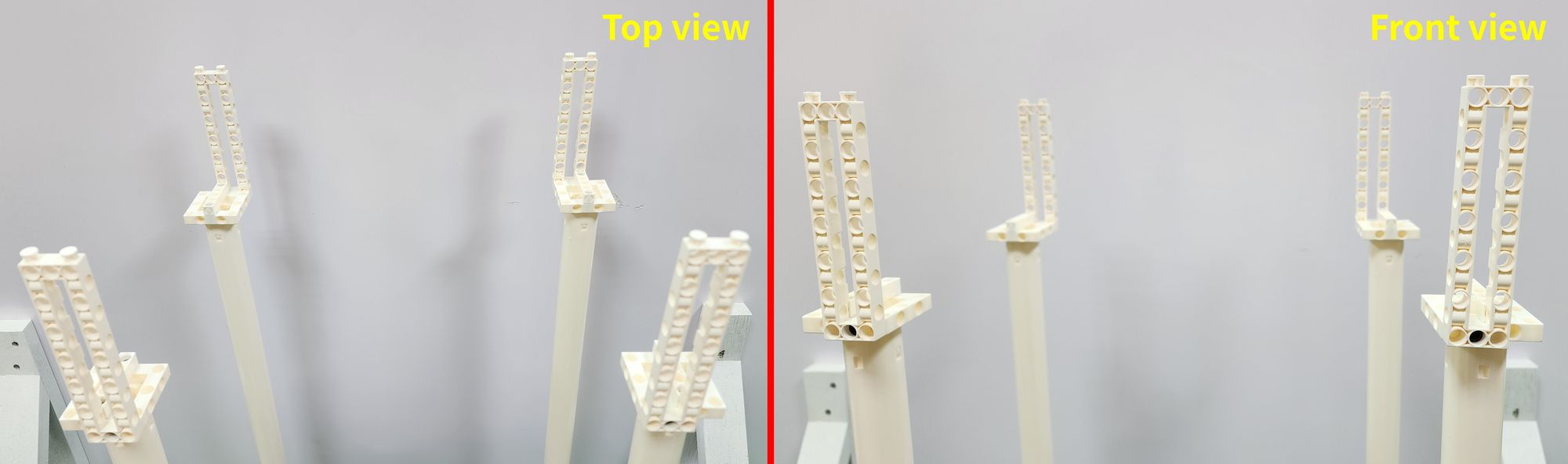
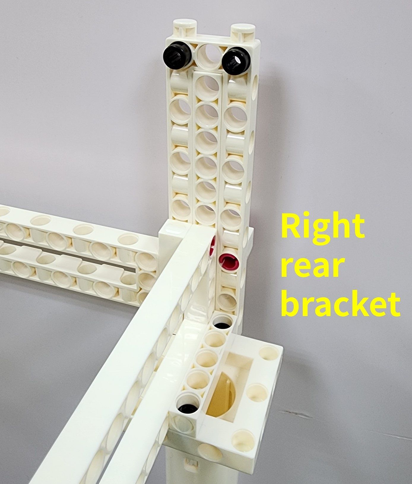
Once we've completed the installation of all the C-3×13 DUAL FRAME, we can double-check their positions, especially those located at the left rear and right rear. They should also be positioned close to the inner side of the centerline and installed at the rear of the claw machine (Figure 45).
Now we're going to make the crossbar and the front and rear tracks. The crossbar (part B) can be used to secure the brackets of the claw machine, making its structure more stable. The front and rear tracks (part C) can hold the carriage, allowing it to move in the forward and backward directions.
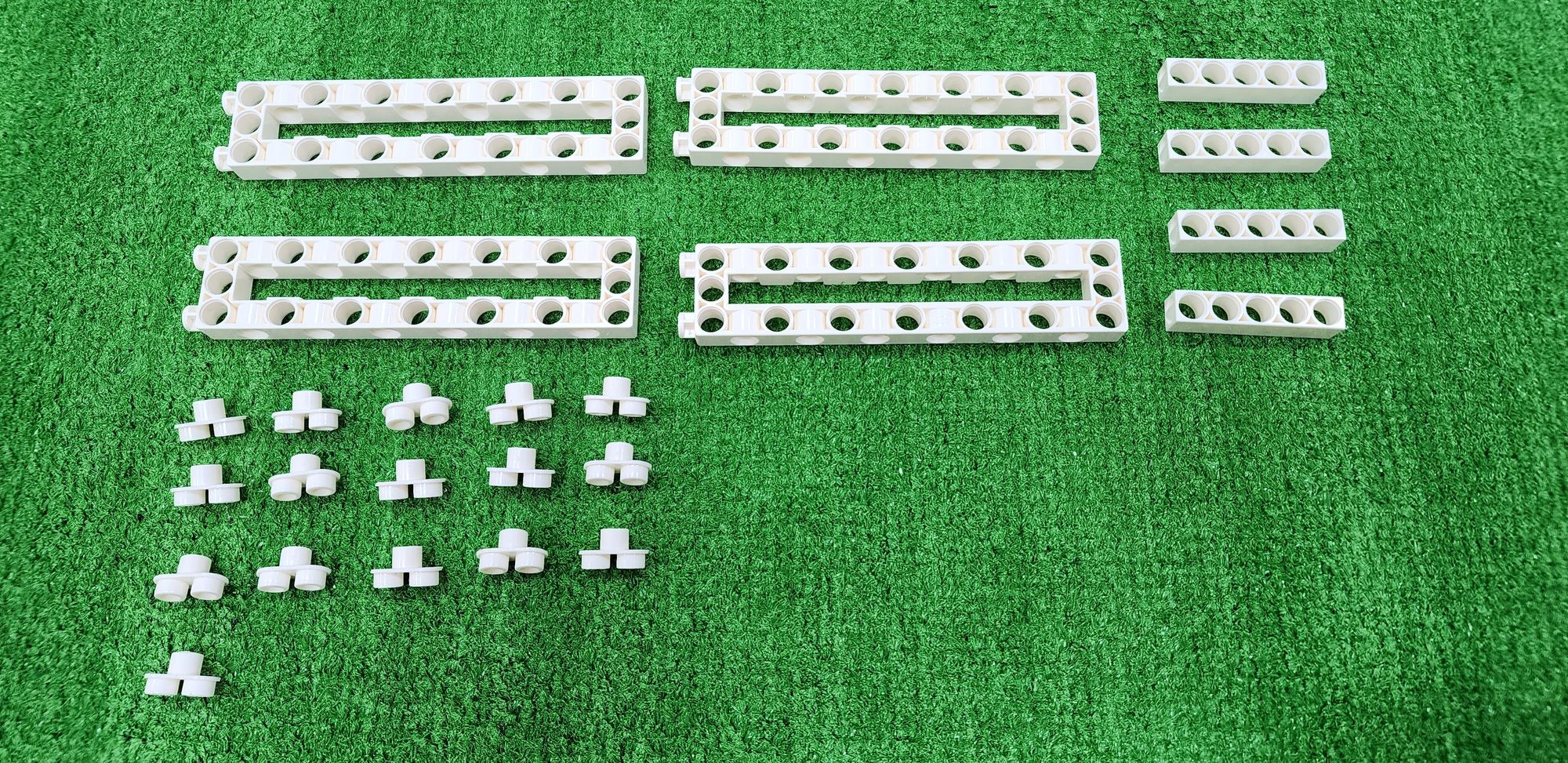
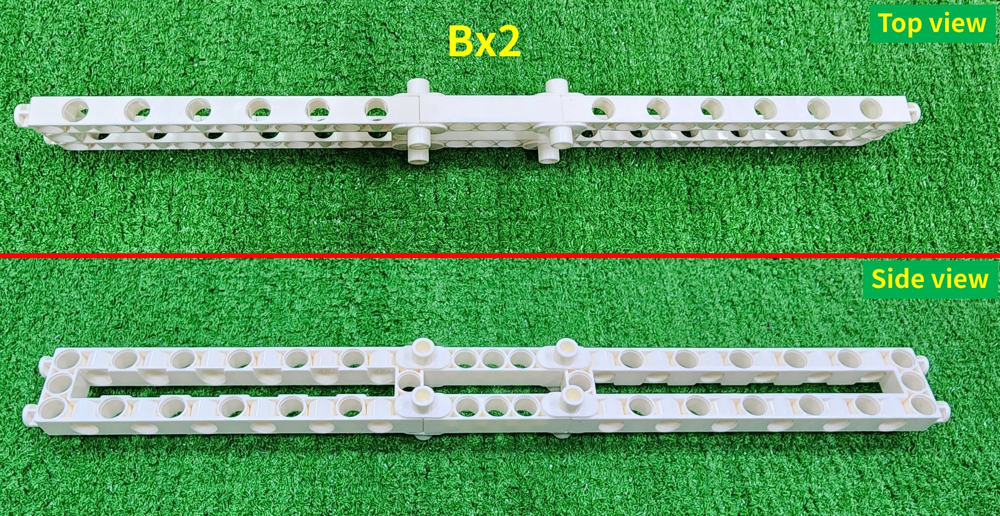
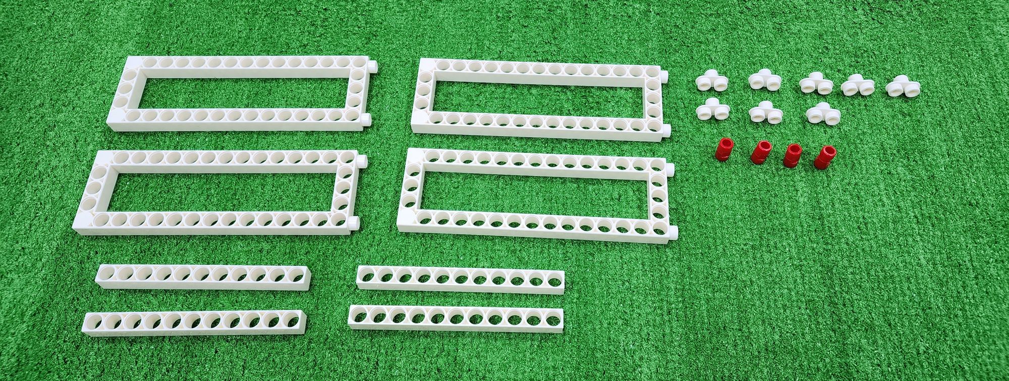
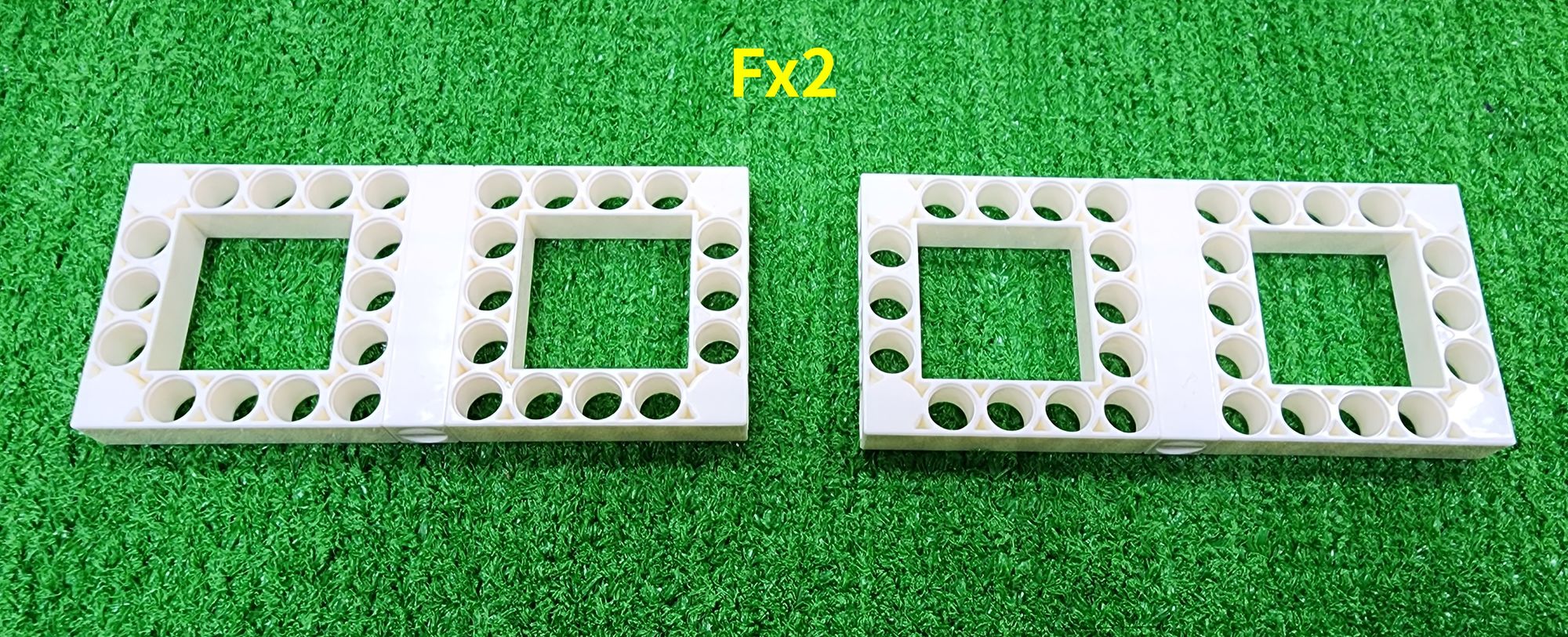
Step 11: We now make the crossbar. We'll need to use the C-3x13 DUAL FRAME, C-5 HOLE ROD, and C-TWO-IN-ONE CONVERTER (Figure 46). Combine them to complete the fabrication of two part B components (Figure 47).
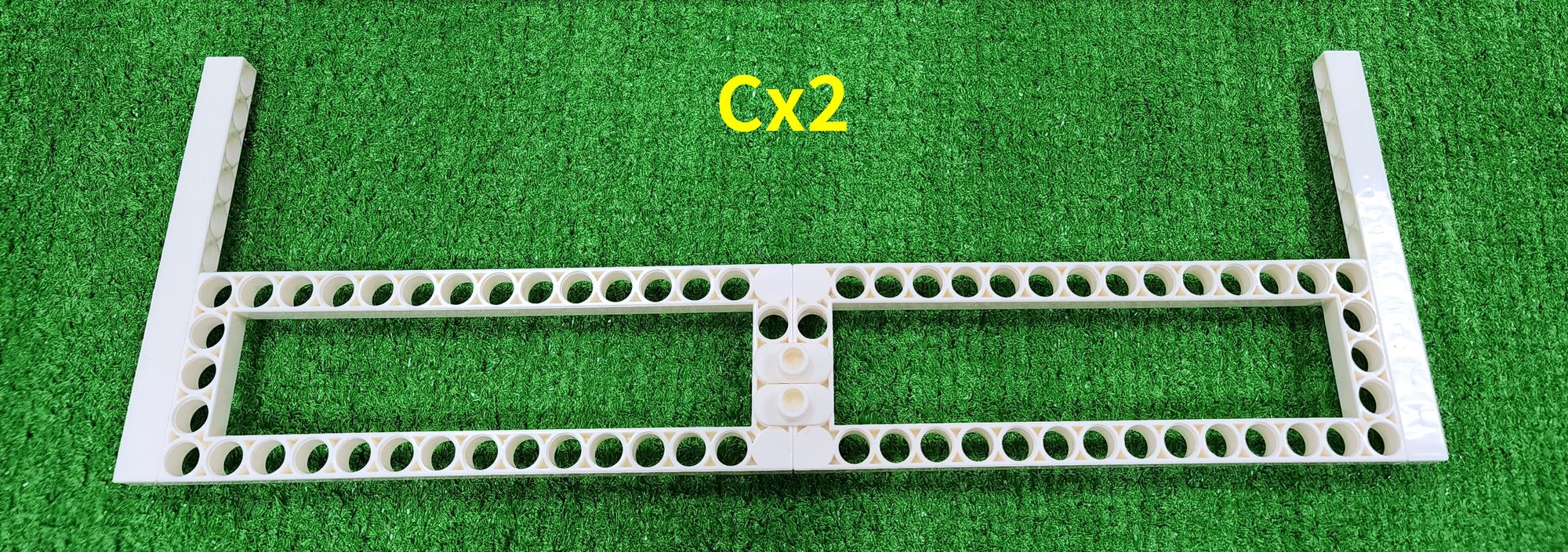
Next, we'll make the front and rear tracks. We'll need to use the C-5×15 FRAME, C-11 HOLE ROD, C-TWO-IN-ONE CONVERTER, and C-LONG PEG (Figure 48). Combine them to complete the fabrication of two part C components (Figure 49).
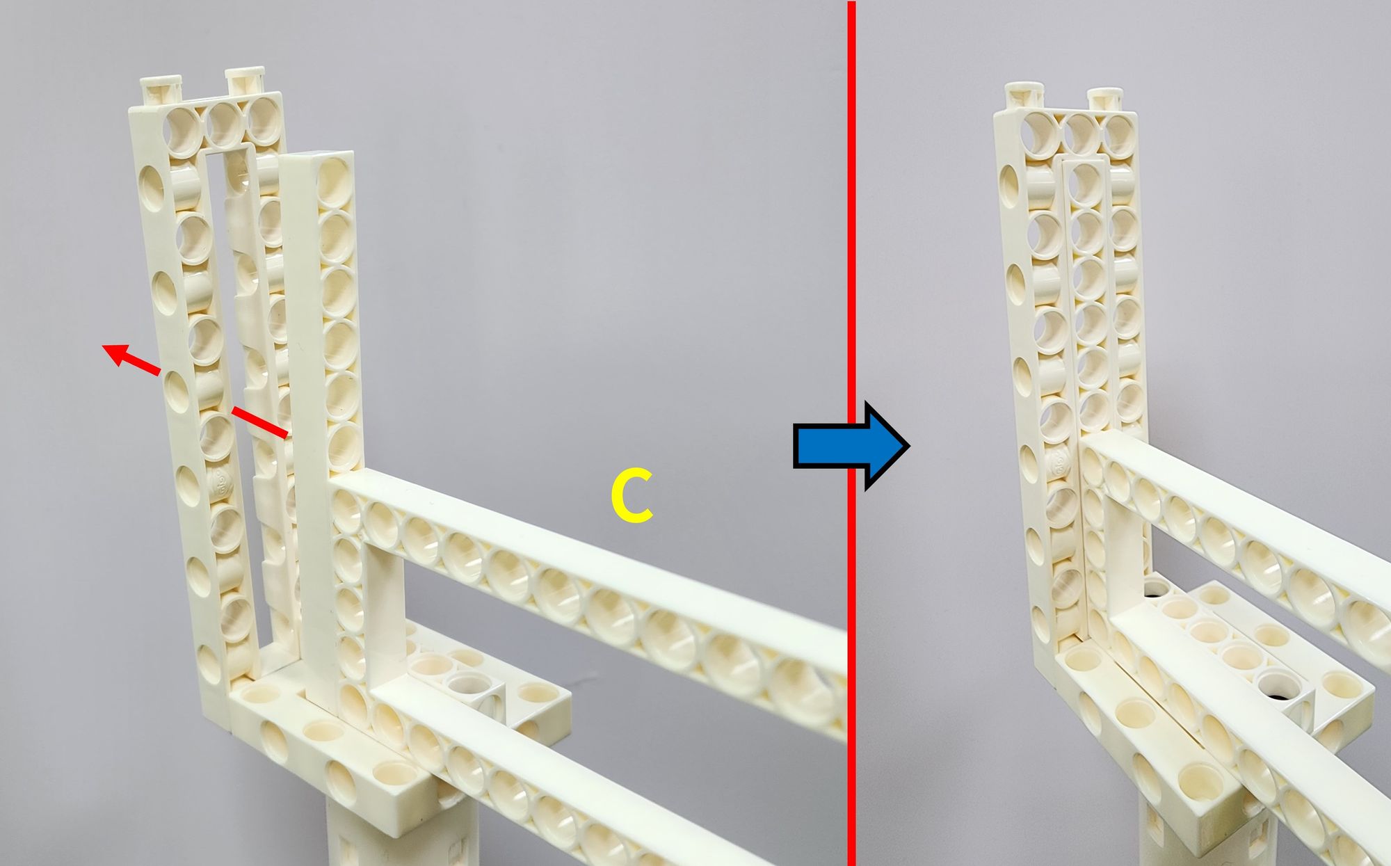
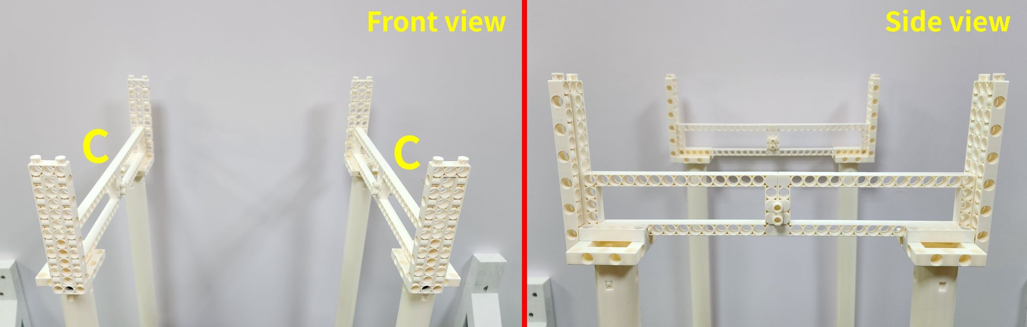
Step 12: We secure the front and rear tracks to the brackets. Place the ends of part C into the holes in the middle of the front and rear C-3x13 DUAL FRAME (Figure 50), and complete the installation of two part C components following this method (Figure 51).
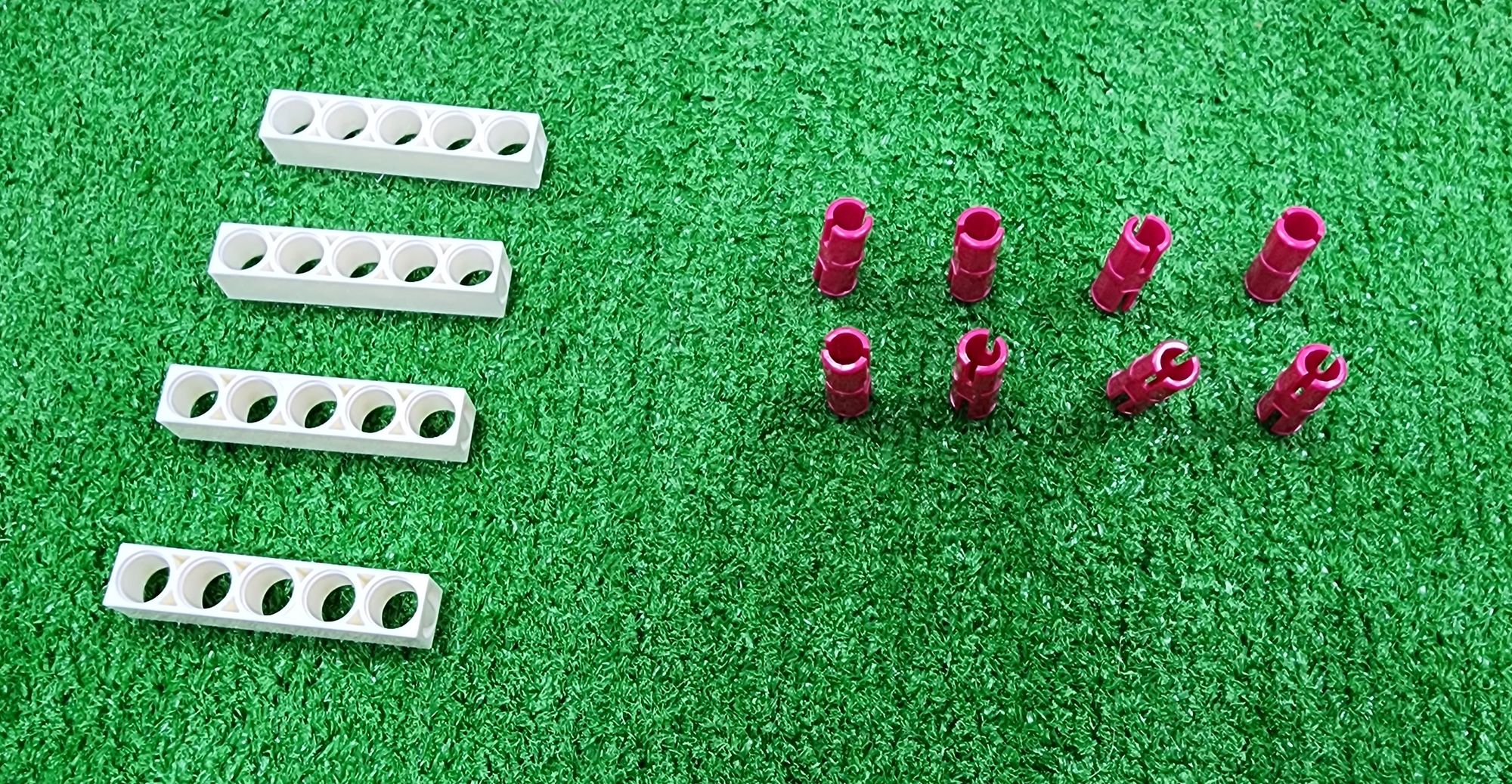
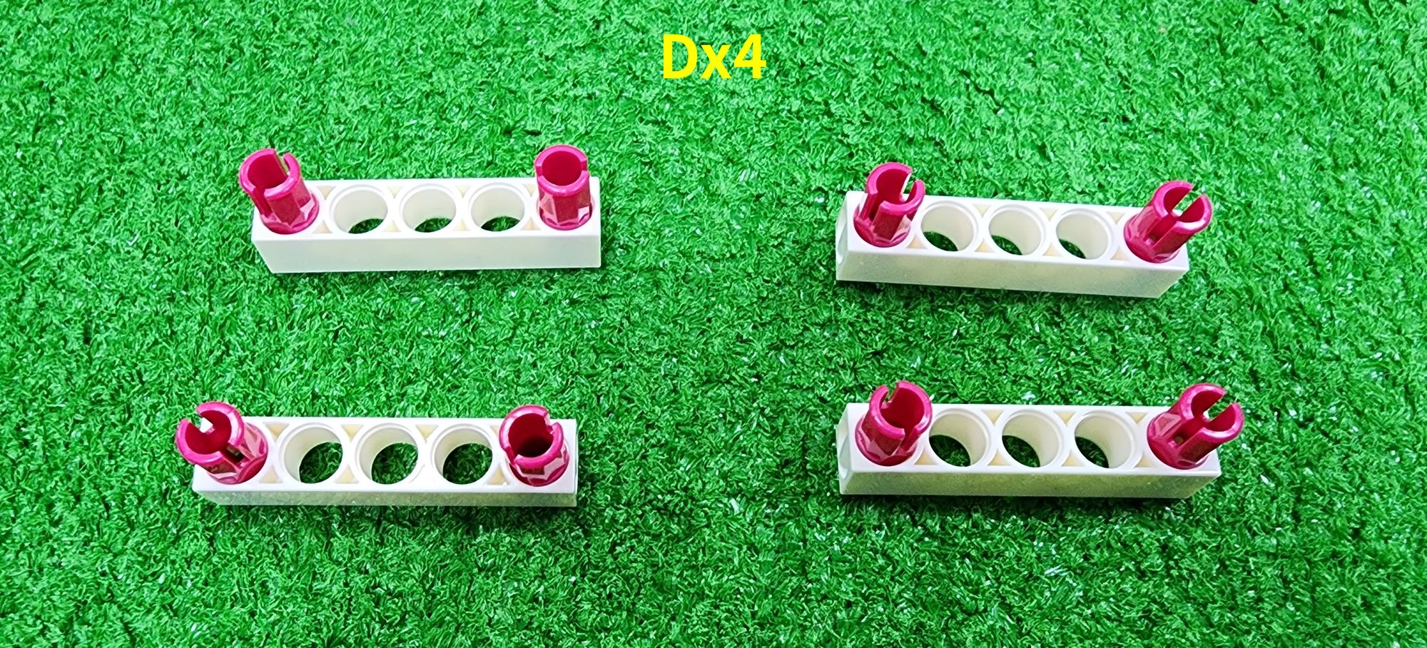
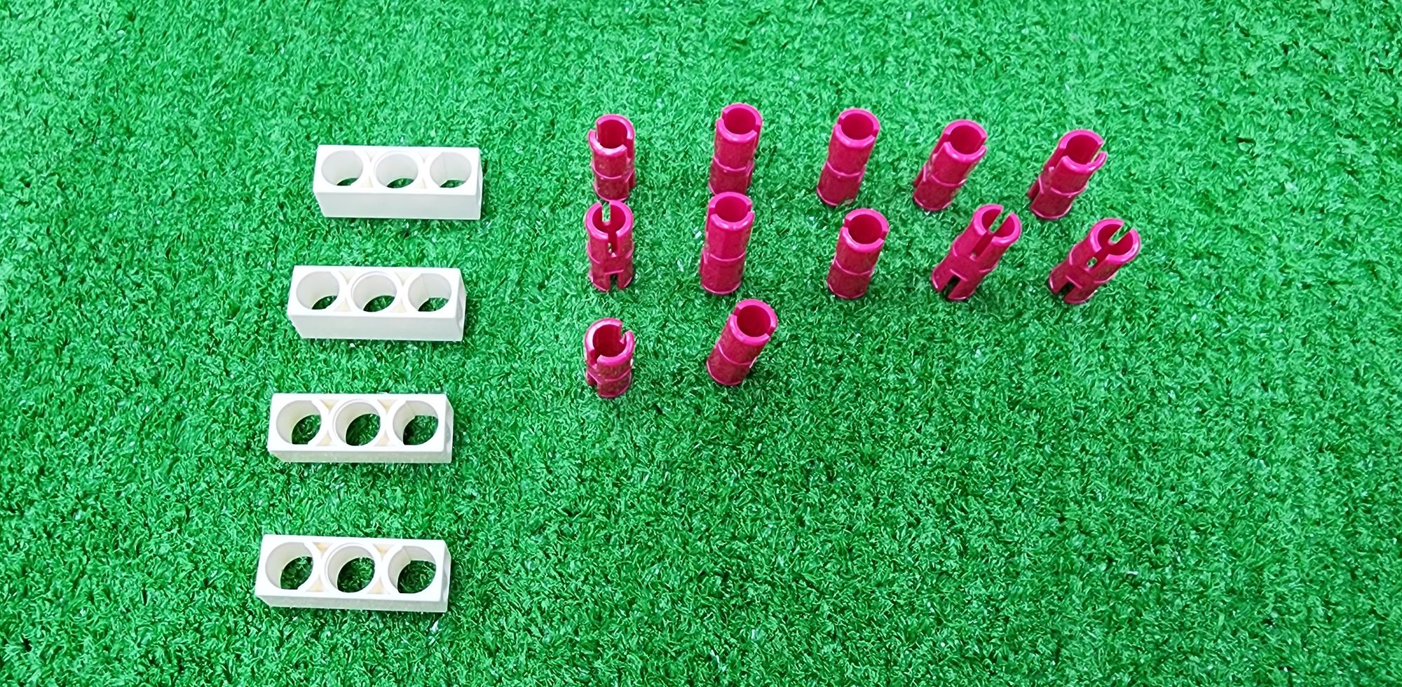
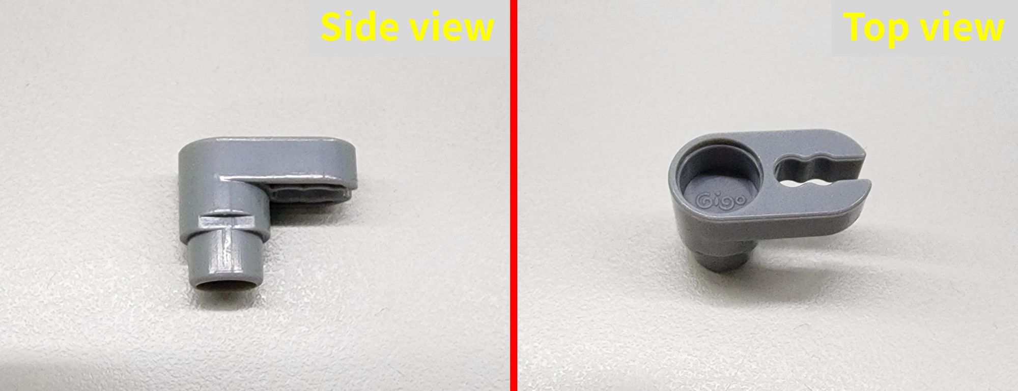
Step 13: We add some design elements above part C to connect part B. We'll need to use C-5 HOLE ROD and C-STATIC AXLE CONNECTOR (1187-W10-E1K) (Figure 52). Combine them to complete the fabrication of four part D components (Figure 53).
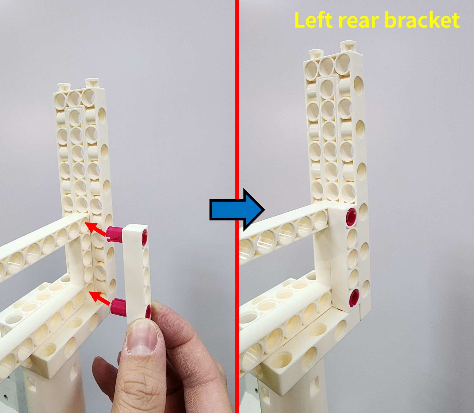
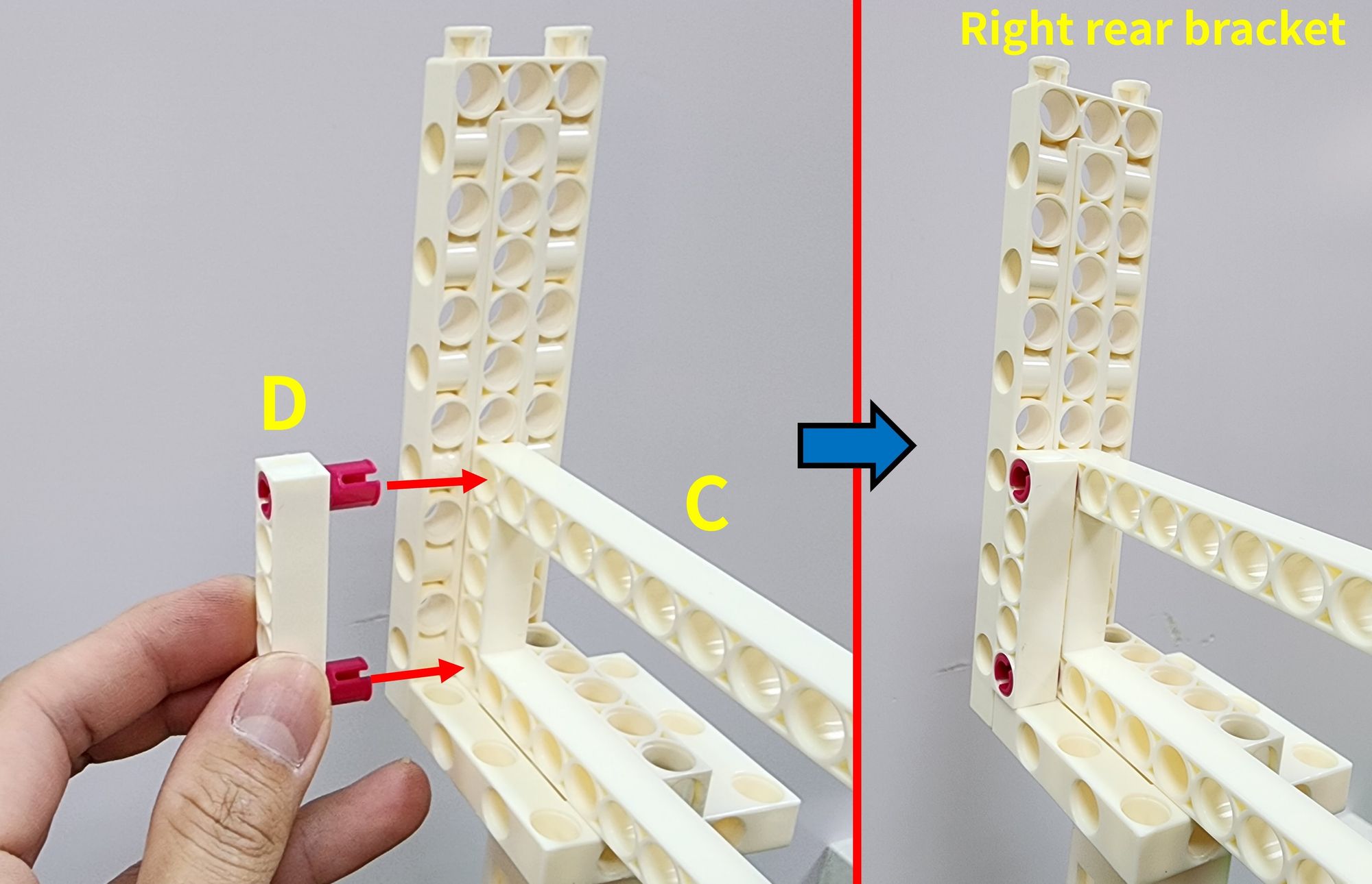
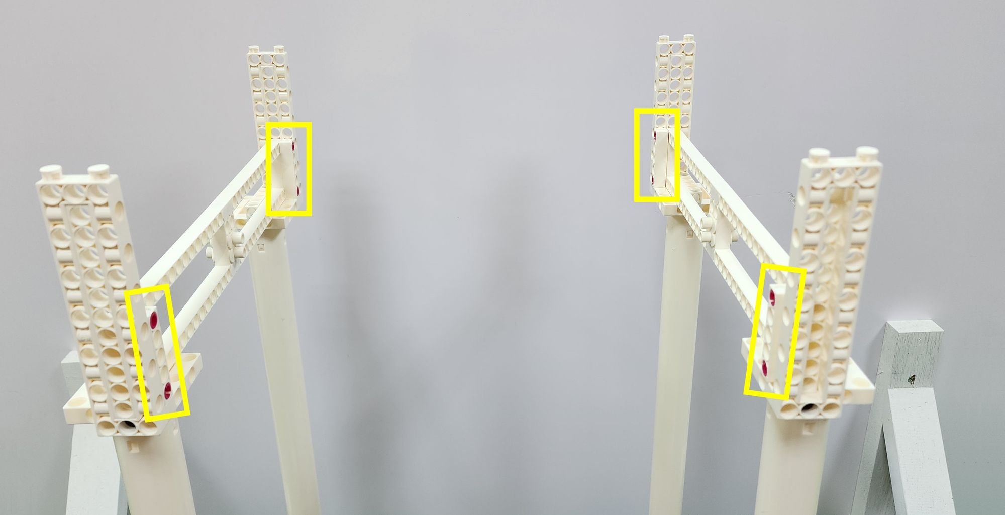
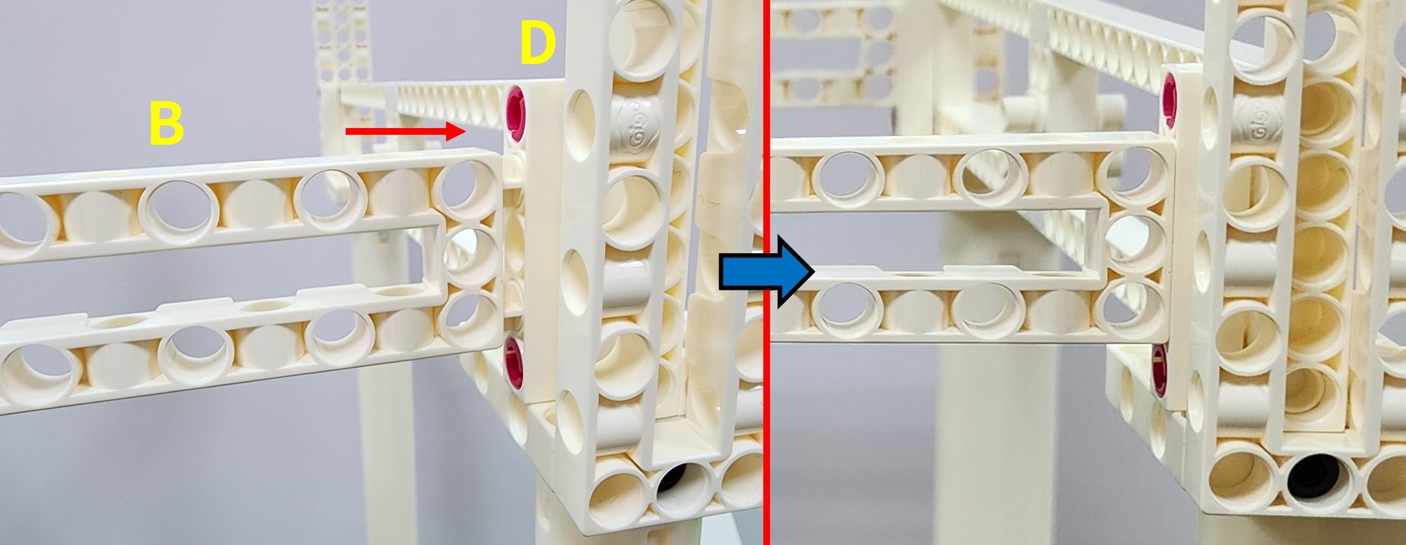
Next, install the completed part D onto part C (Figure 54, Figure 55). After completion, it's essential to check whether part D is correctly installed on the inside of both left and right sets of part C components (Figure 56).
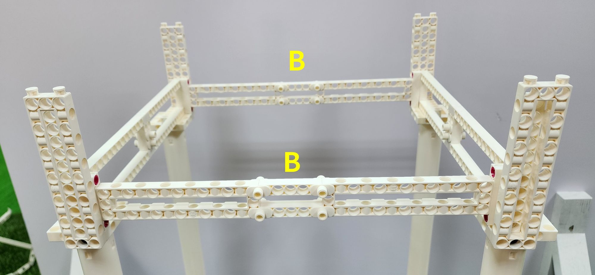
Step 14: We now need to install the crossbar. Attach the recently completed part B to the left and right part D components (Figure 57). This way, the crossbar, brackets, and front and rear tracks can all be connected (Figure 58).
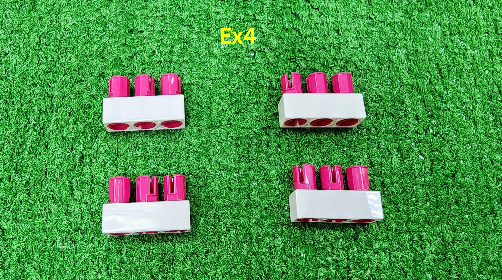
Step 15: We reinforce the front and rear tracks. We need to use C-3 HOLE ROD and C-STATIC AXLE CONNECTOR (Figure 59). Combine them to complete the fabrication of four part E components (Figure 60).
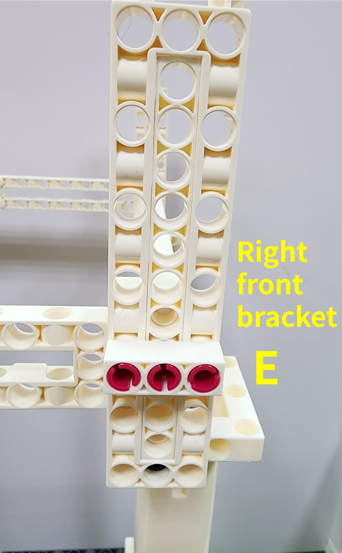
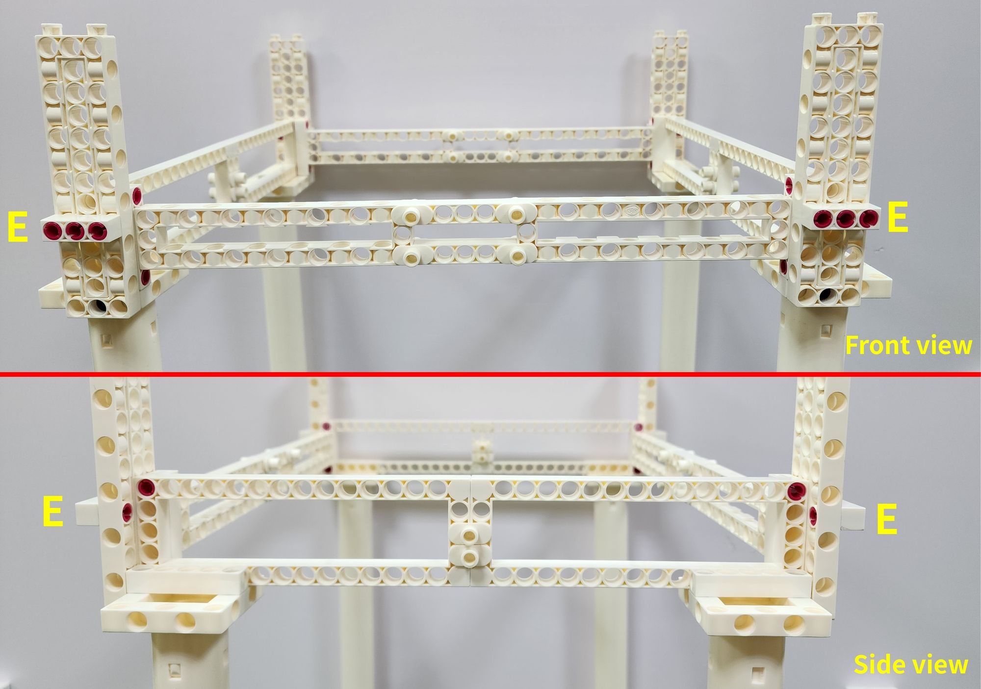
Next, install the completed part E onto part C and the brackets (Figure 61). After completion, it's essential to check whether all four part E components are correctly installed at the front and rear of the claw machine (Figure 62).
Finally, we need to use B-SHORT PEG (Figure 63) to assemble them onto the C-3x13 DUAL FRAME on the brackets (Figure 64).
After completion, it's essential to check whether the B-SHORT PEG are correctly installed on the inside of the claw machine (Figure 65). This design is intended to block the carriage on the tracks, preventing it from derailing when moving to the edges.
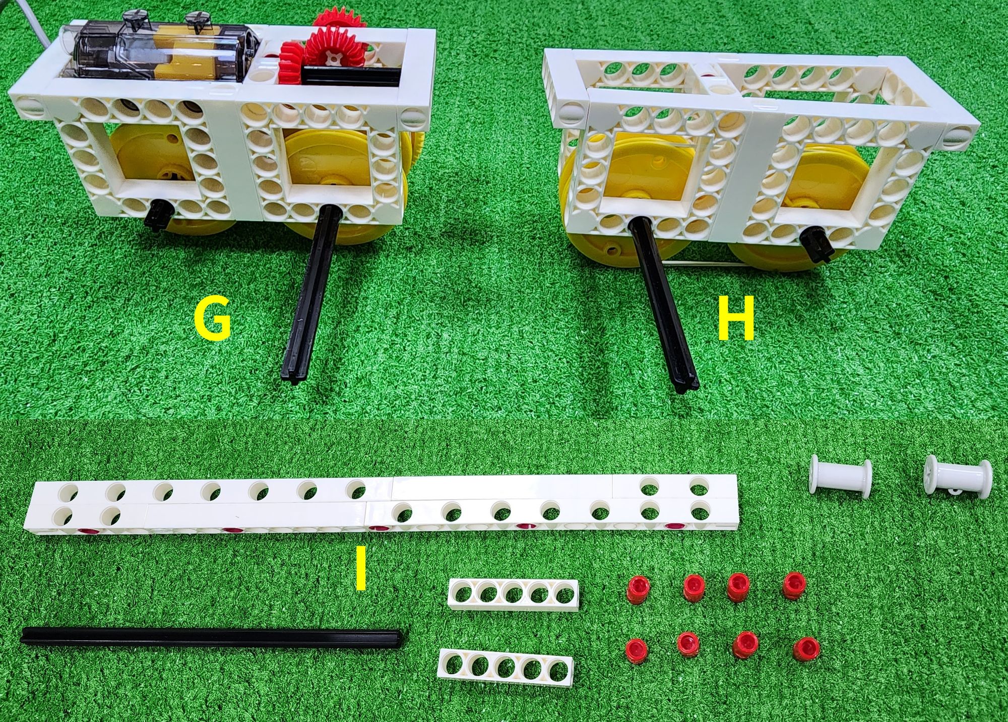
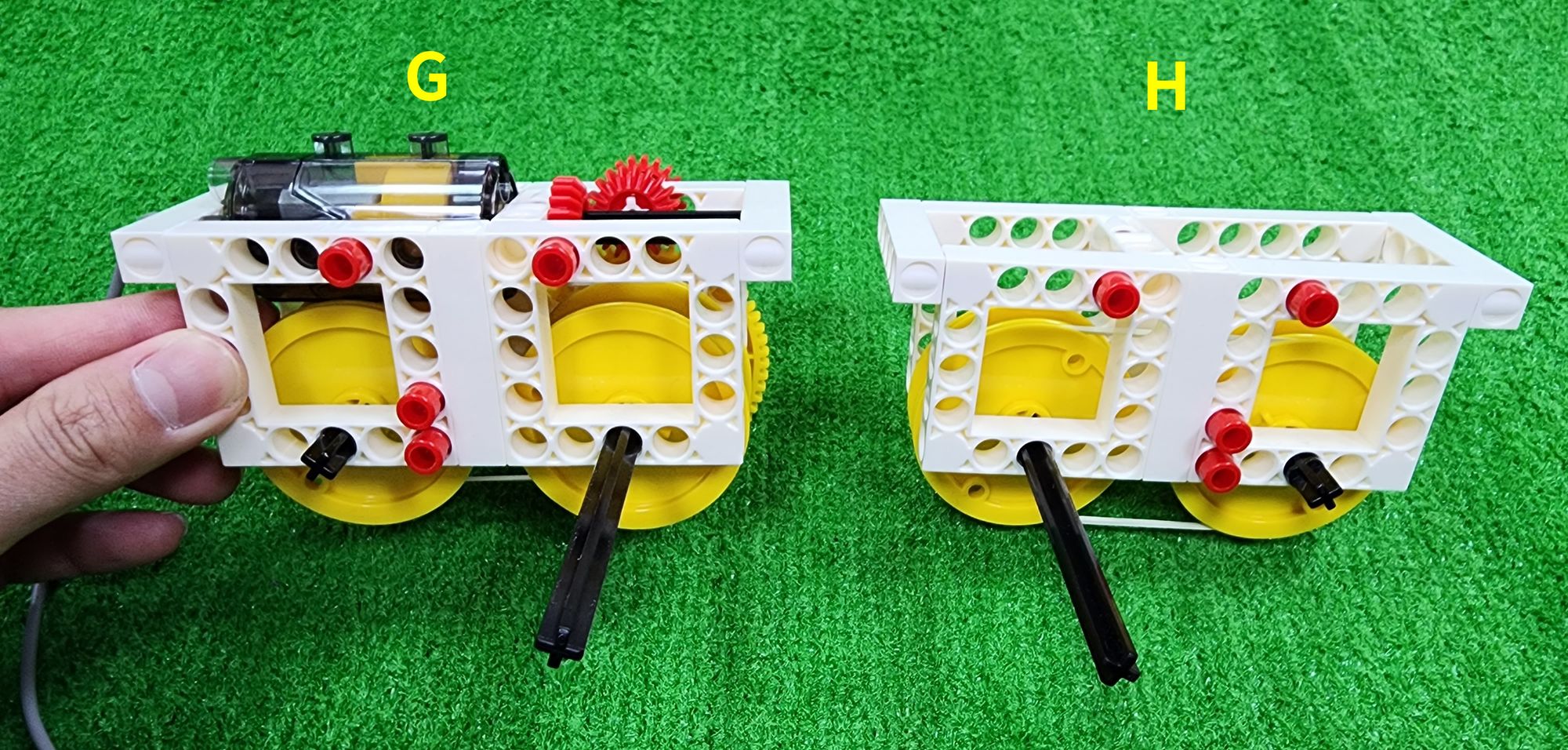
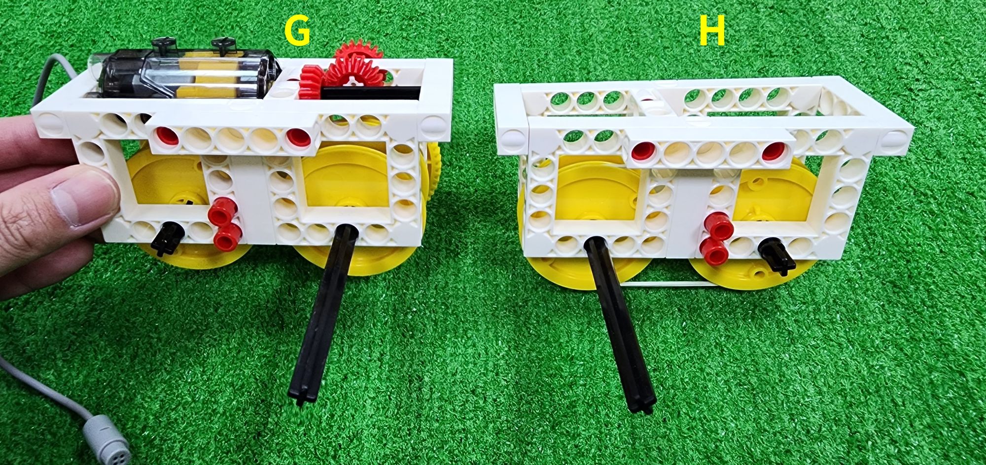
Now we're going to make the front and rear carriages for the claw machine. The front and rear carriages will travel above the front and rear tracks, allowing the claw machine's claw to move forward and backward. They mainly consist of part G, left and right tracks (part I), and part H.
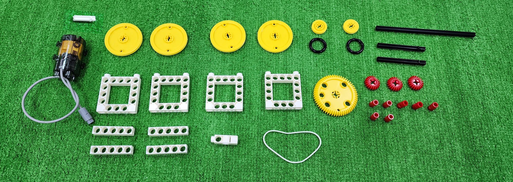
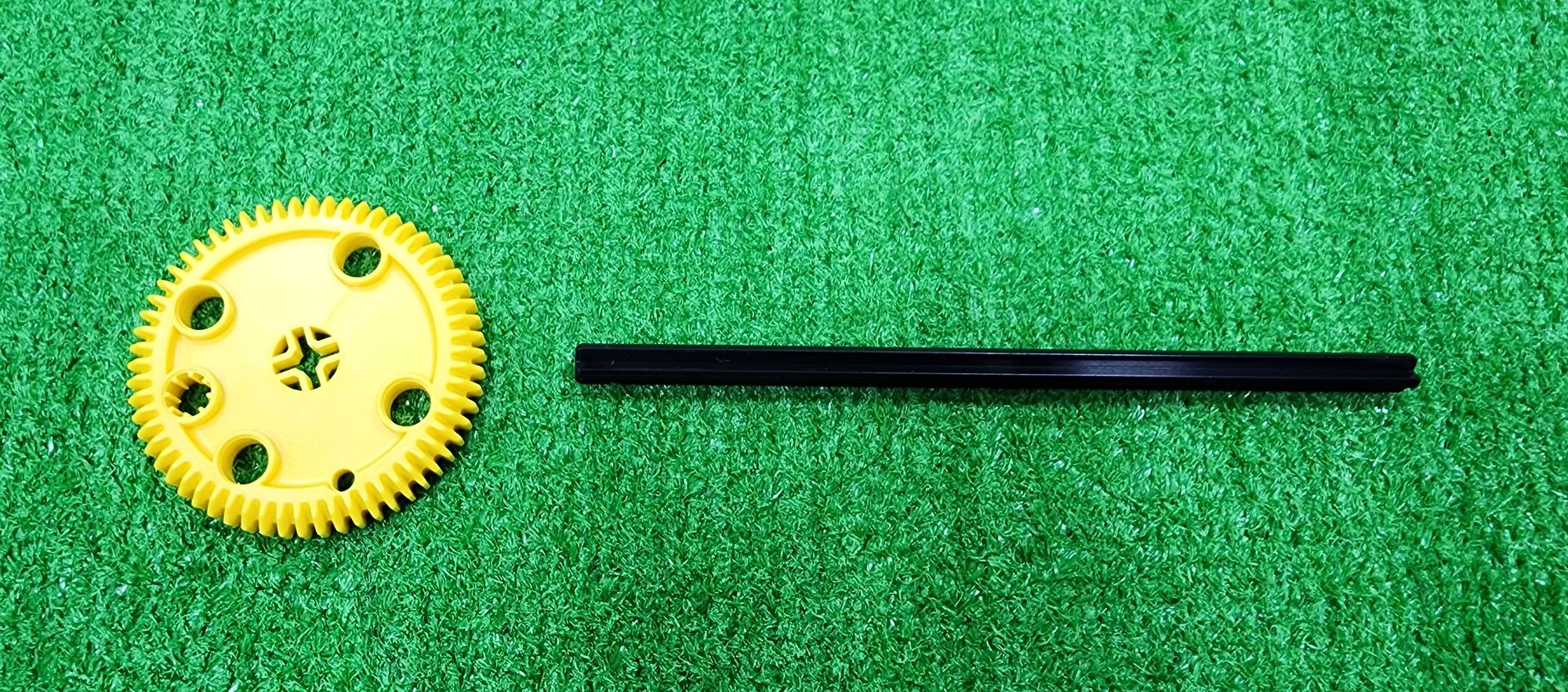
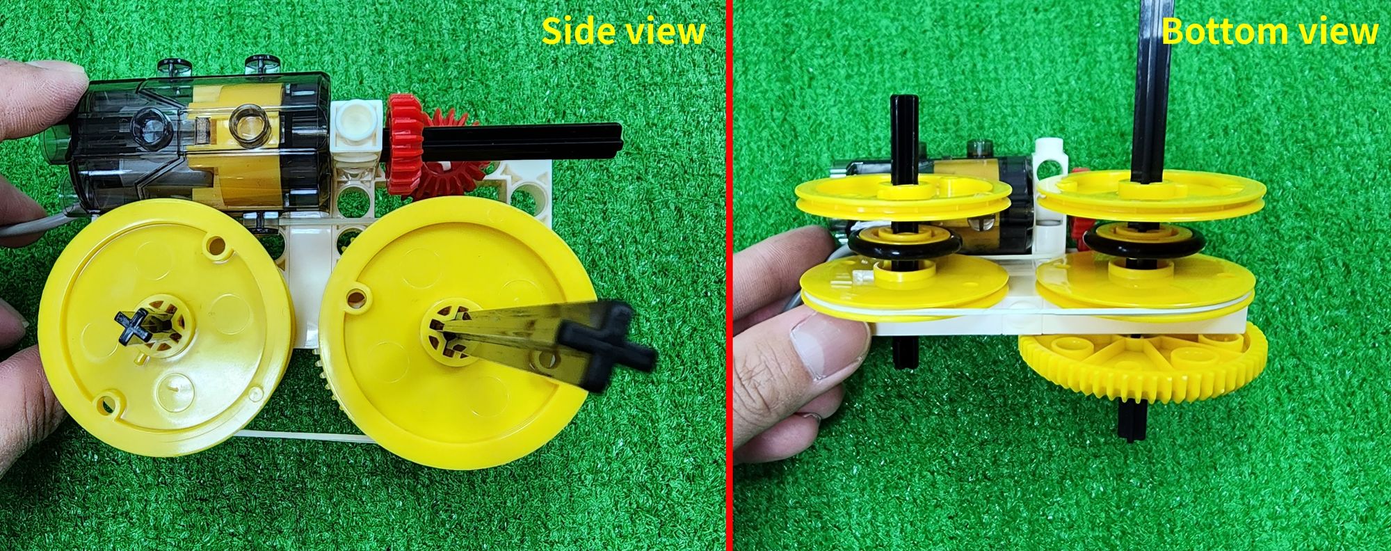
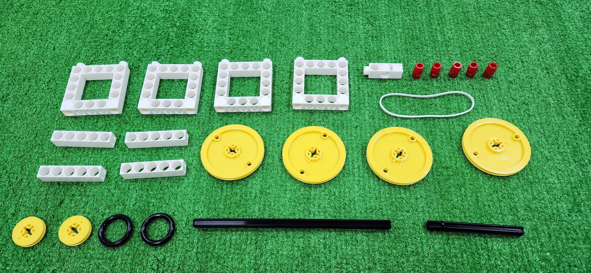
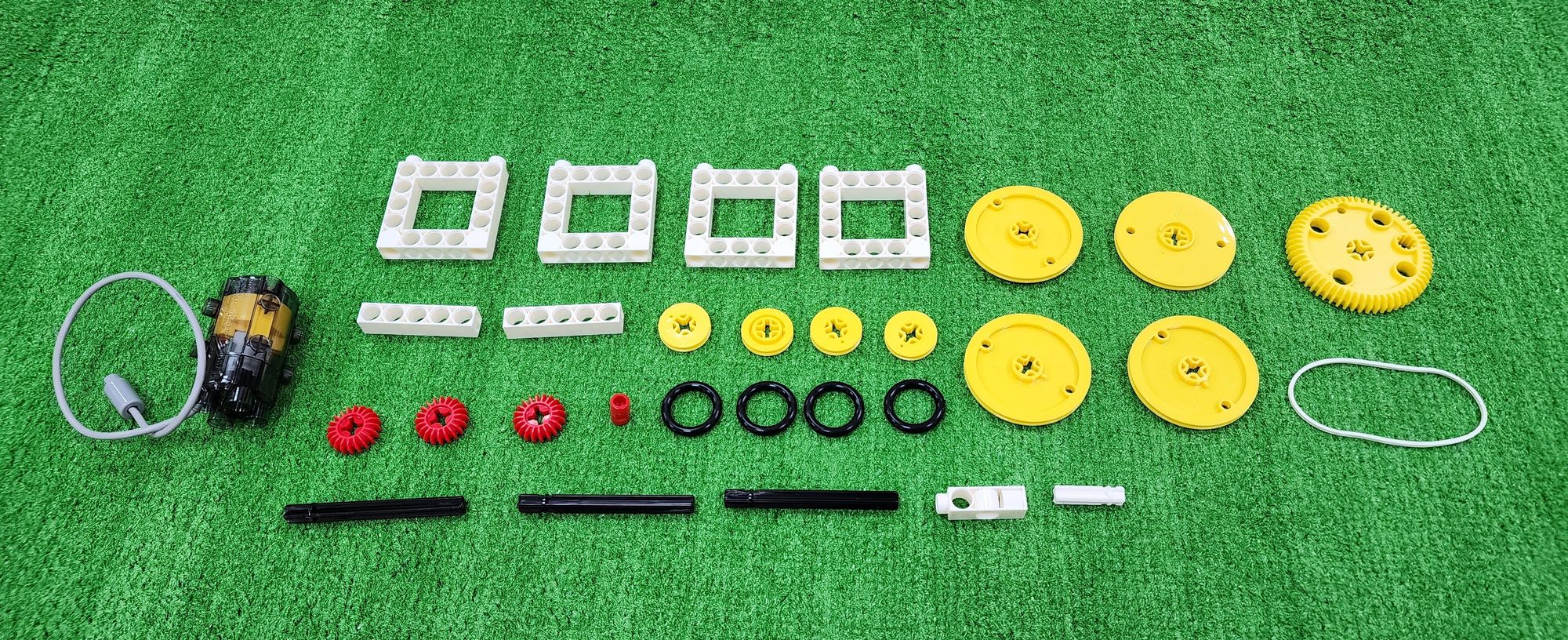
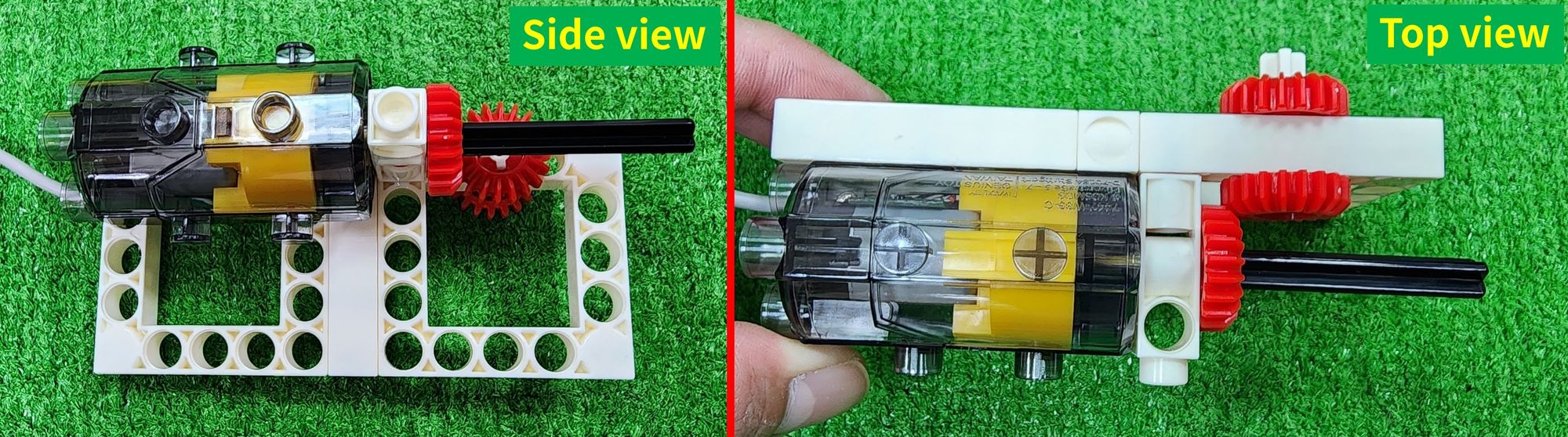
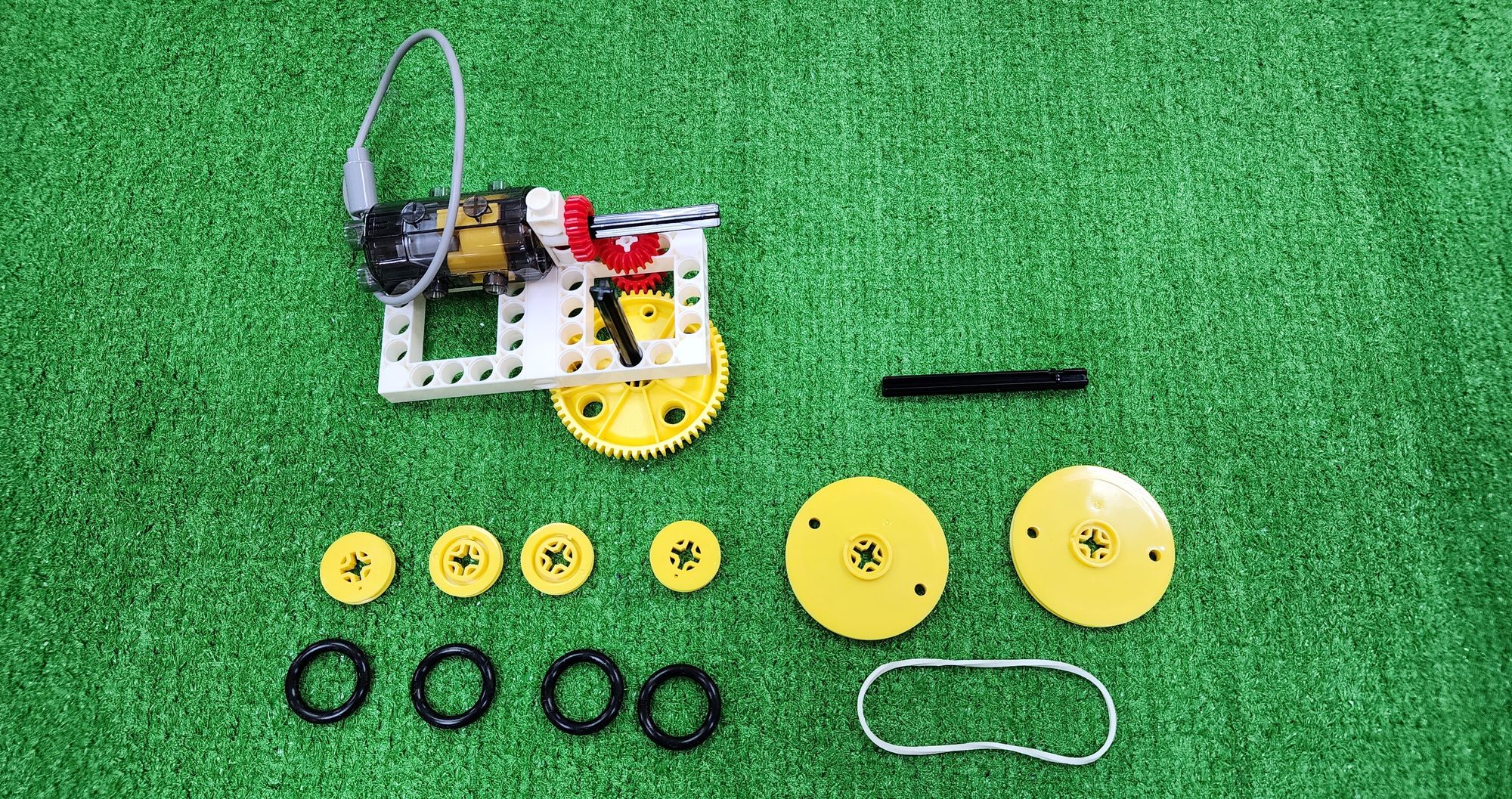
First, let's make part G. part G is the main power source for the front and rear carriages. For the one located on the left side of the claw machine, we'll need to use C-5×5 FRAME, C-5 HOLE ROD, C-3 HOLE DUAL ROD, C-70mm AXLE Ⅱ, C-150mm AXLE Ⅰ, C-MOTOR AXLE, C-20T GEAR, C-60T GEAR, C-OD53mm PULLEY, C-OD23mm PULLEY, C-OD26 O-RING, C-LONG PEG, C-70mm RUBBER BAND, and a C-50X PLANETARY GEARBOX (Figure 66).
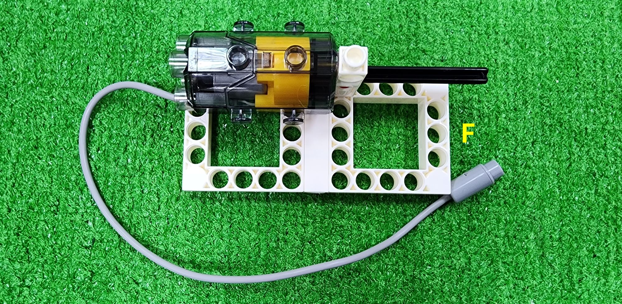
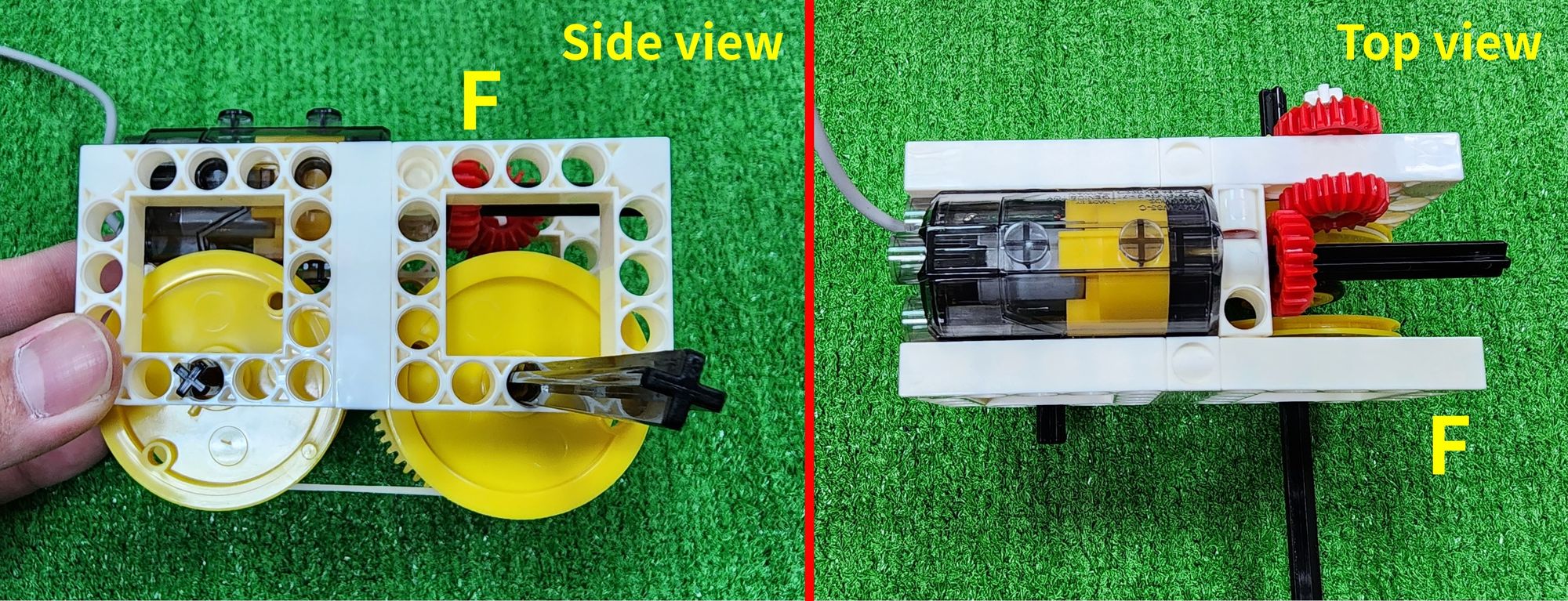
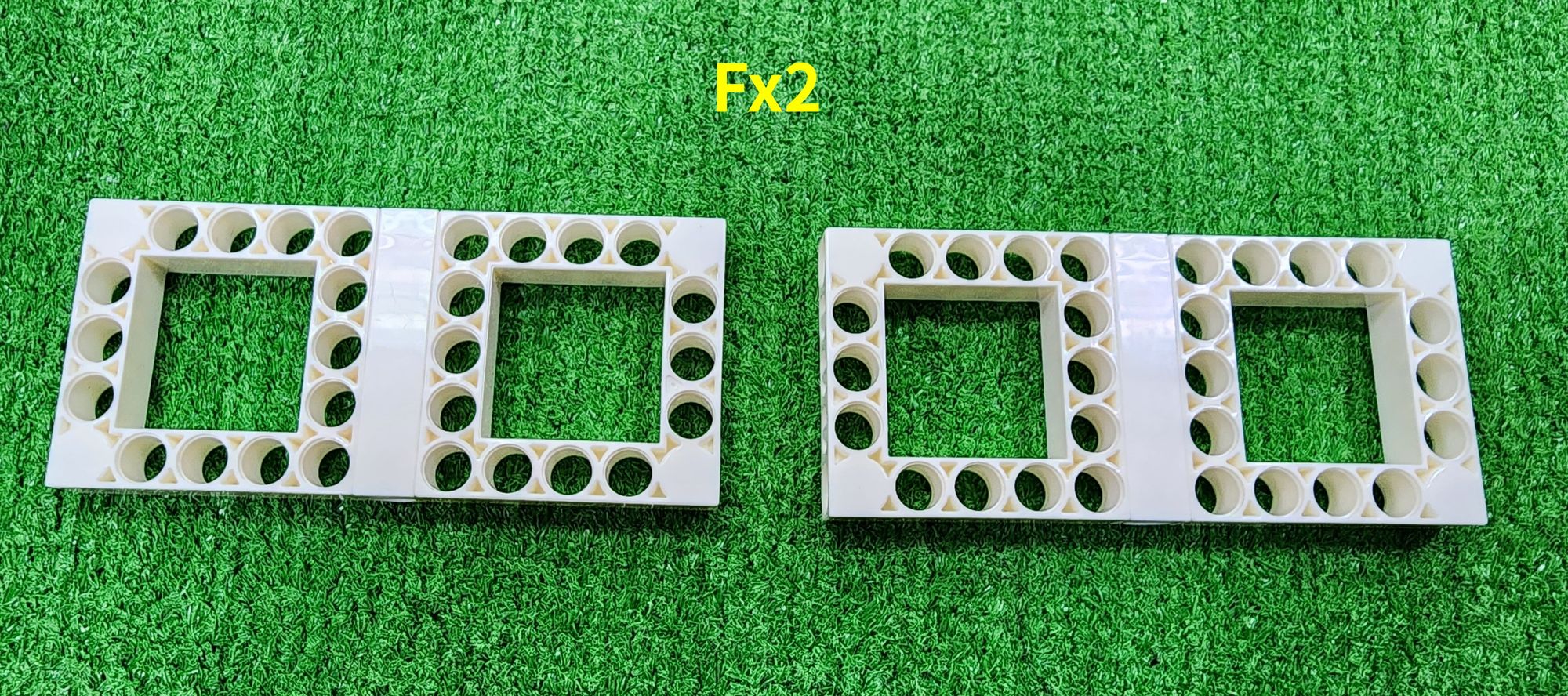
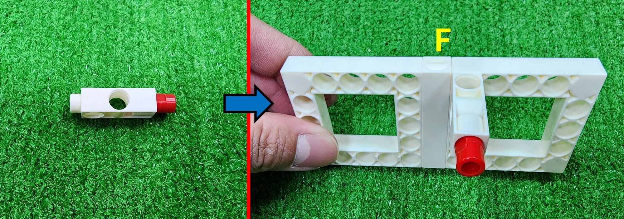
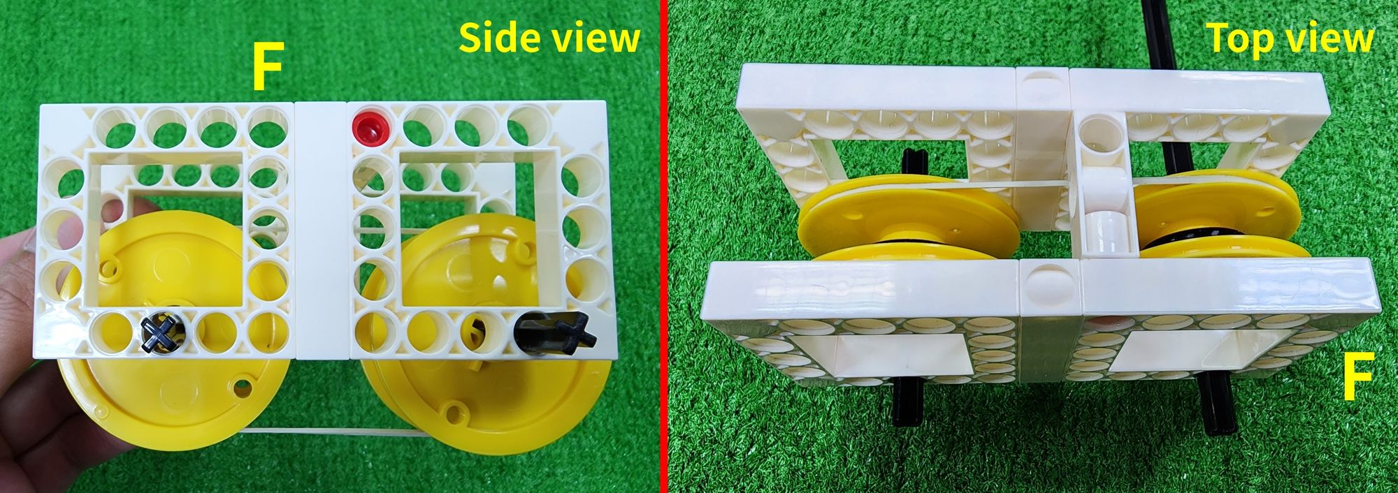
Step 16: We assemble the C-5×5 FRAME and the C-5 HOLE ROD to complete the fabrication of two part F components (Figure 67).

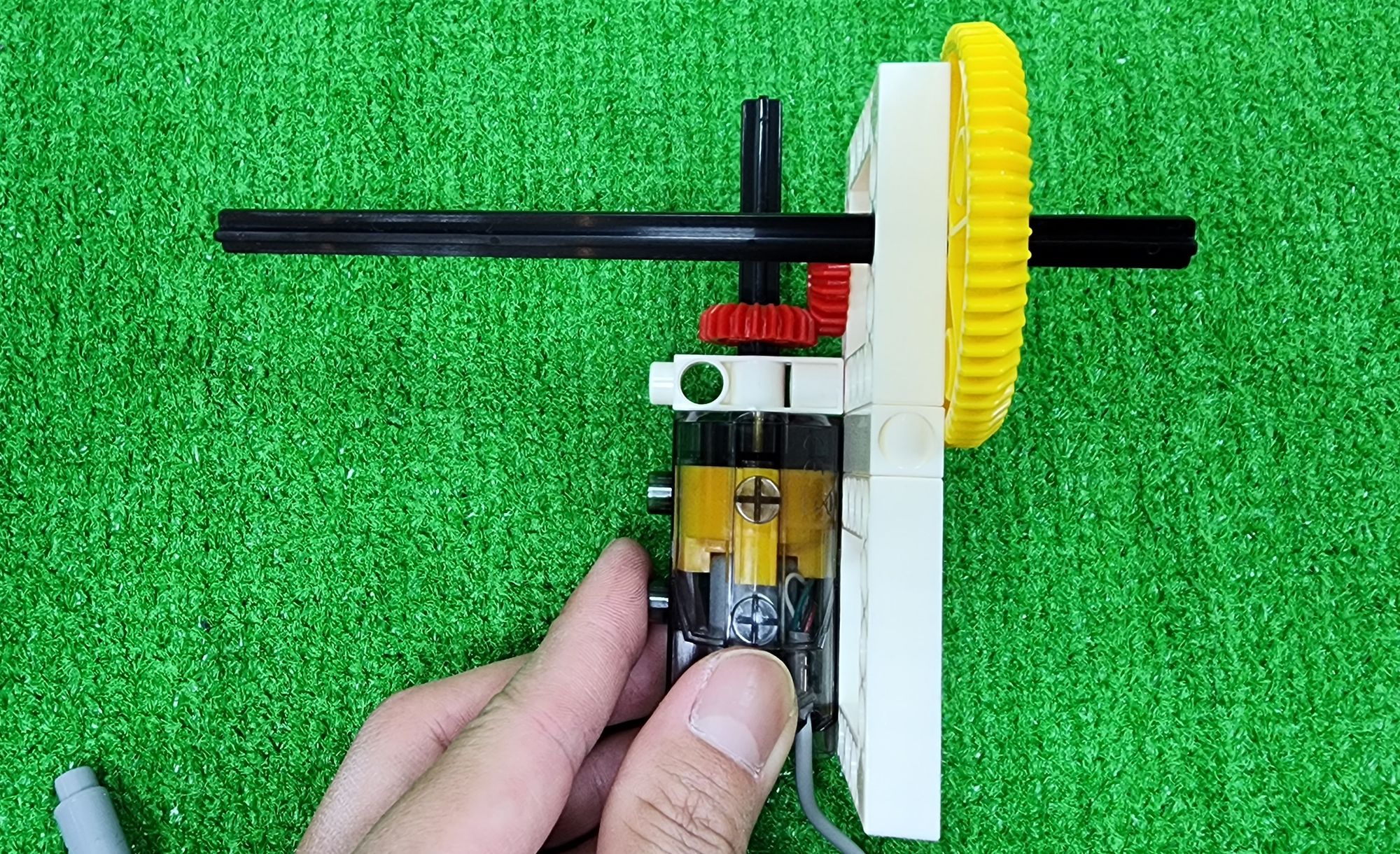
Step 17: We'll insert the C-70mm AXLE Ⅱ into the C-50X PLANETARY GEARBOX as shown, and then fit it into the C-3 HOLE DUAL ROD with the C-LONG PEG (Figure 68). Next, we'll mount the C-50X PLANETARY GEARBOX onto part F (Figure 69), and finally, insert the C-20T GEAR into the C-70mm AXLE Ⅱ (Figure 70).
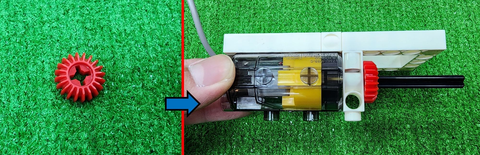
Step 18: We need to use the C-MOTOR AXLE and the C-20T GEAR (Figure 71). Follow the diagram to install the C-20T GEAR on both sides of part F, ensuring that the inner C-20T GEAR mesh with the C-20T GEAR on the C-70mm AXLE Ⅱ (Figure 72).
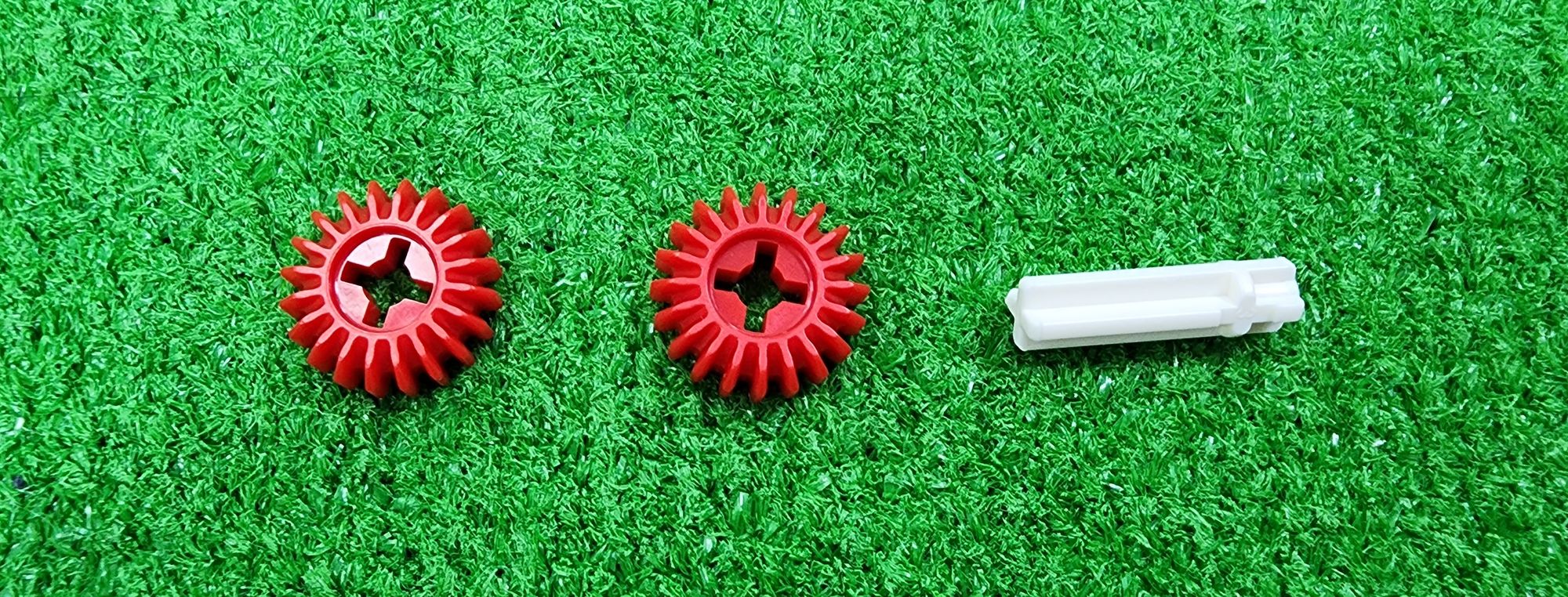
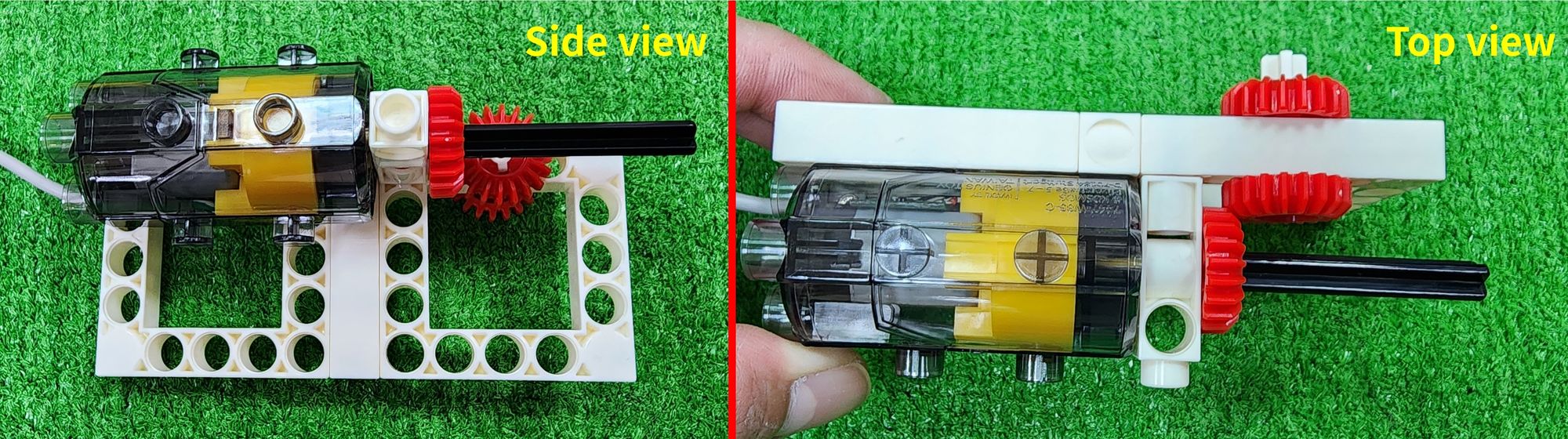
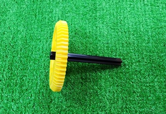
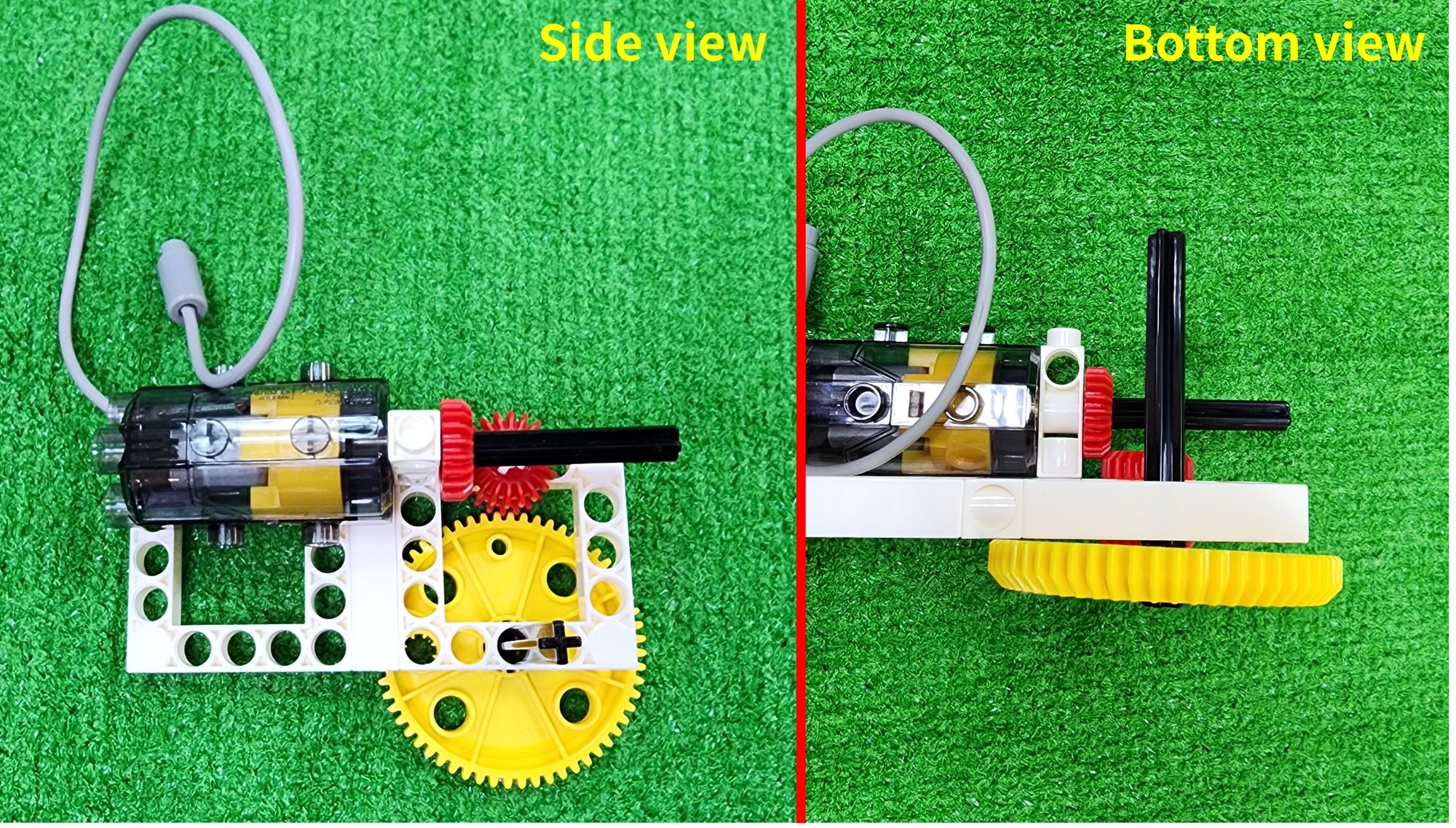
Step 19: We need to use of the C-150mm AXLE Ⅰ and the C-60T GEAR (Figure 73). Install the C-150mm AXLE Ⅰ and the C-60T GEAR (Figure 74).
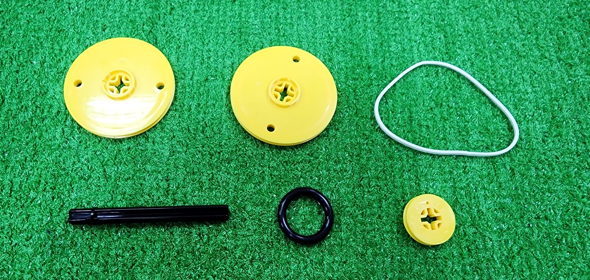
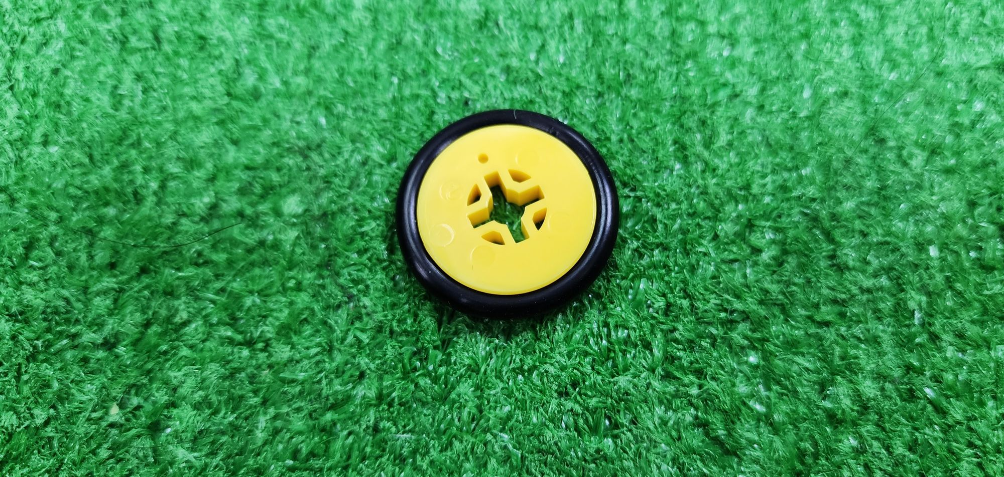
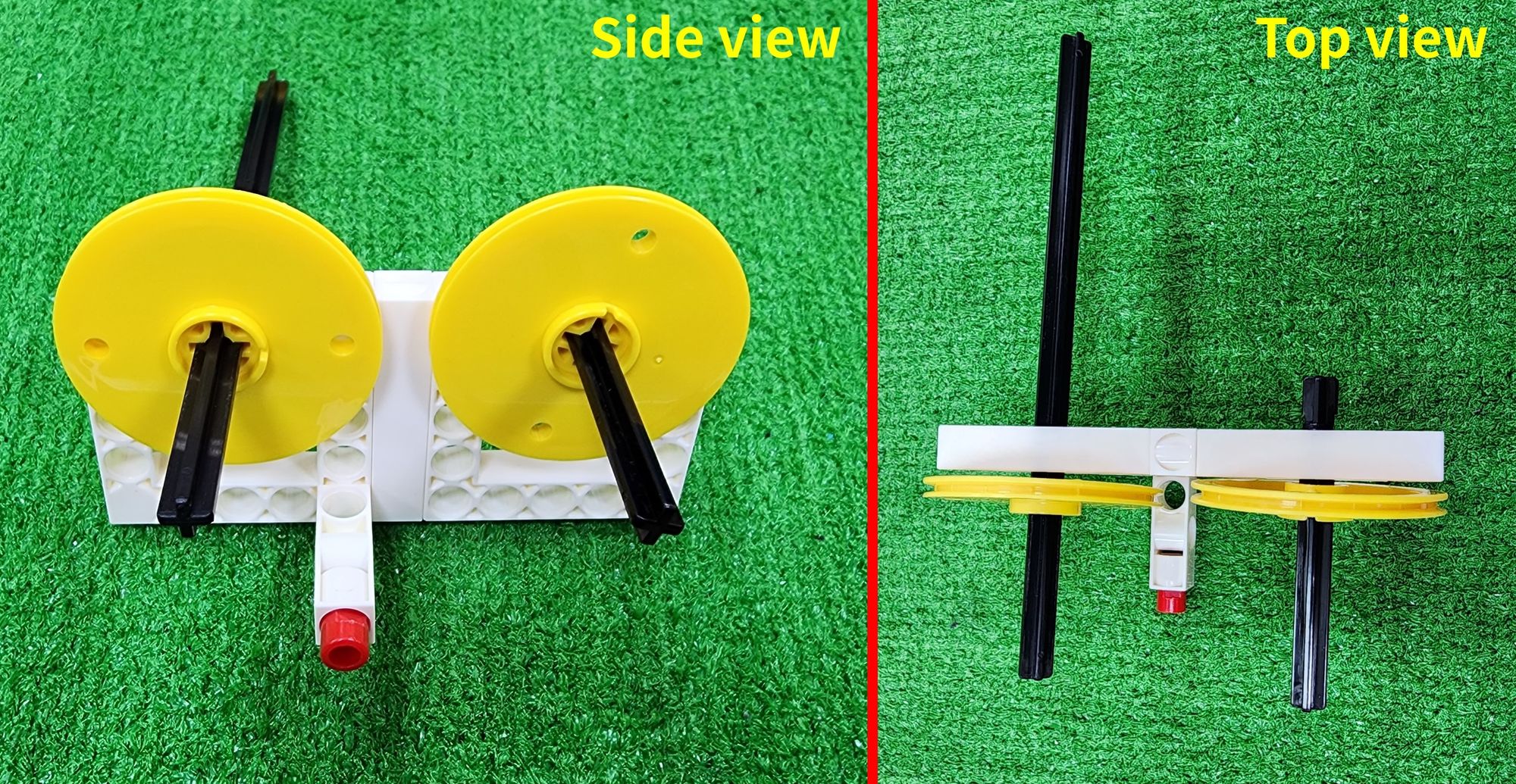
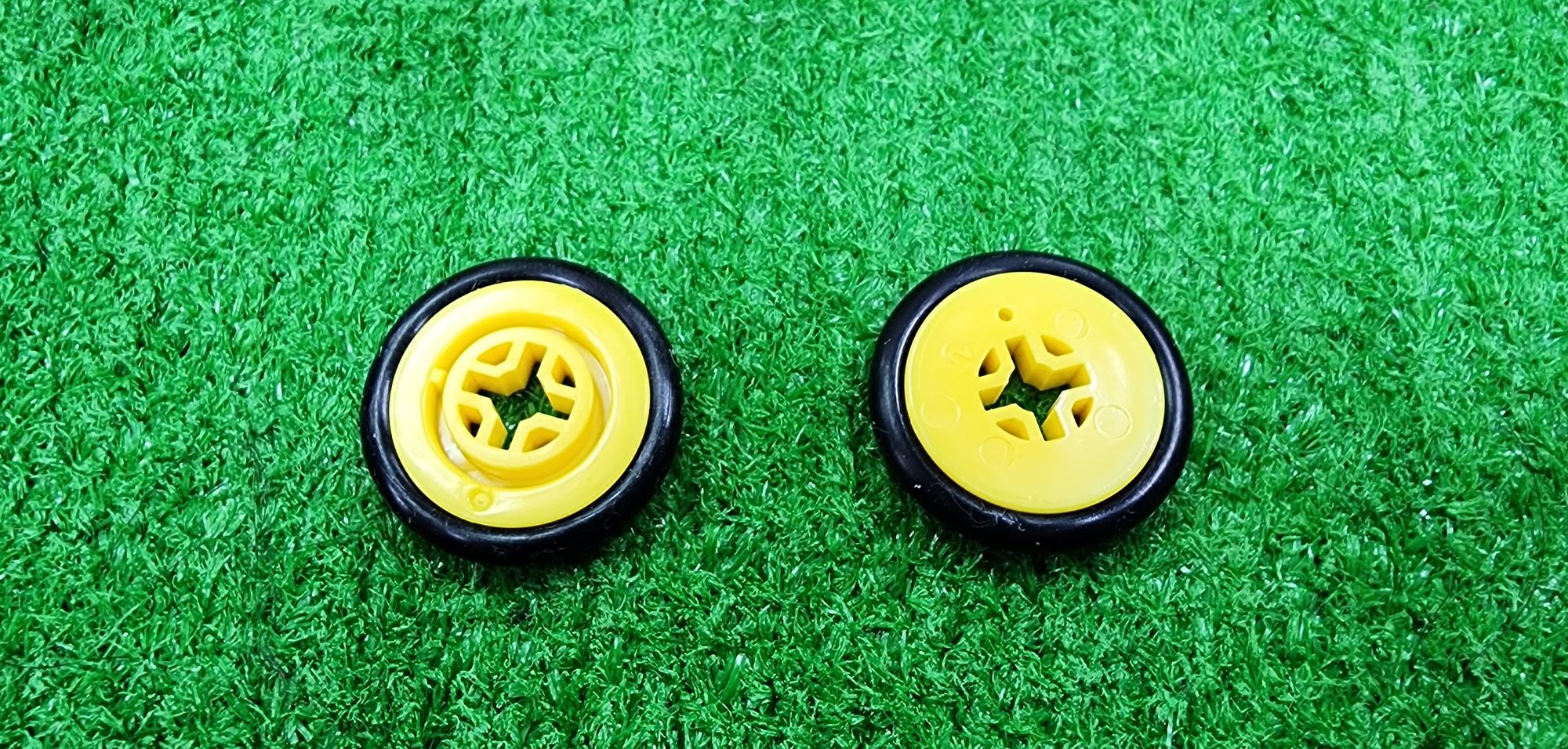
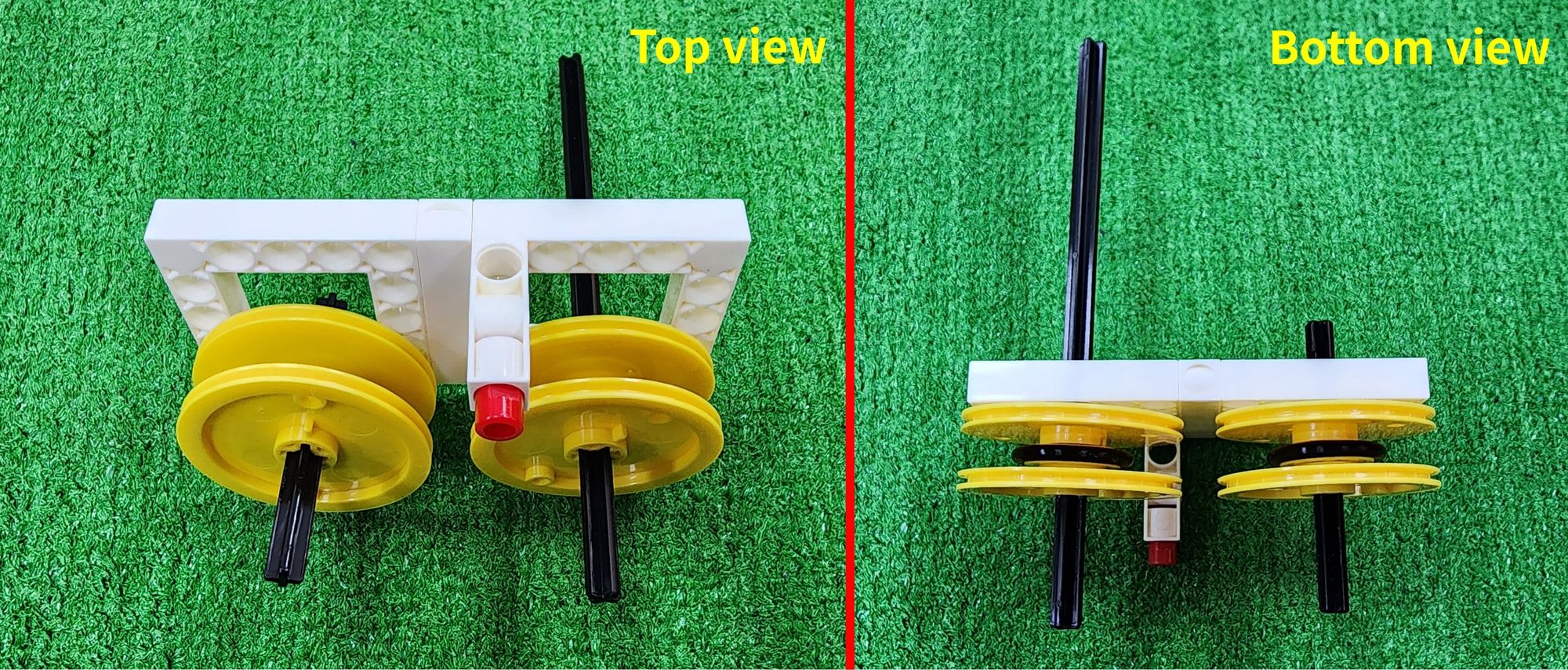
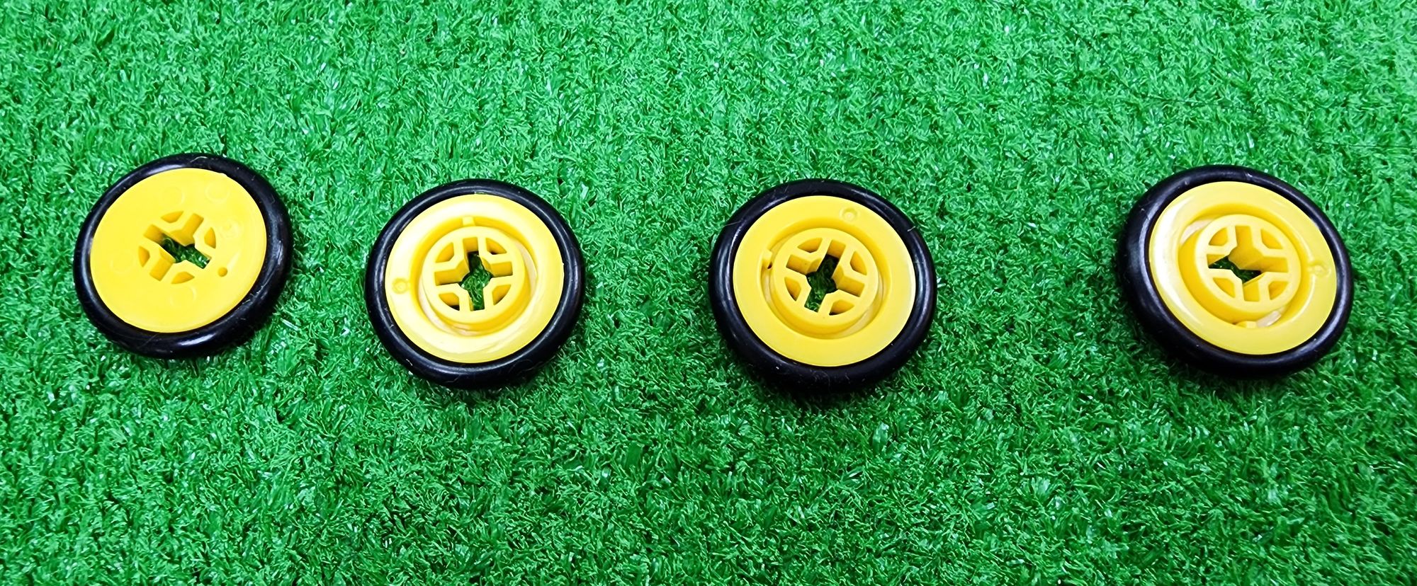
Step 20: It requires the use of C-OD53mm PULLEY, C-OD23mm PULLEY, and C-OD26mm PULLEY (Figure 75). First, place the C-OD26 O-RING around the outer edge of the C-OD23mm PULLEY (Figure 76). Then, install the C-OD53mm PULLEY and the C-OD23mm PULLEY on the C-150mm AXLE Ⅰ, ensuring that the C-OD23mm PULLEY are positioned between the two C-OD53mm PULLEY (Figure 77).
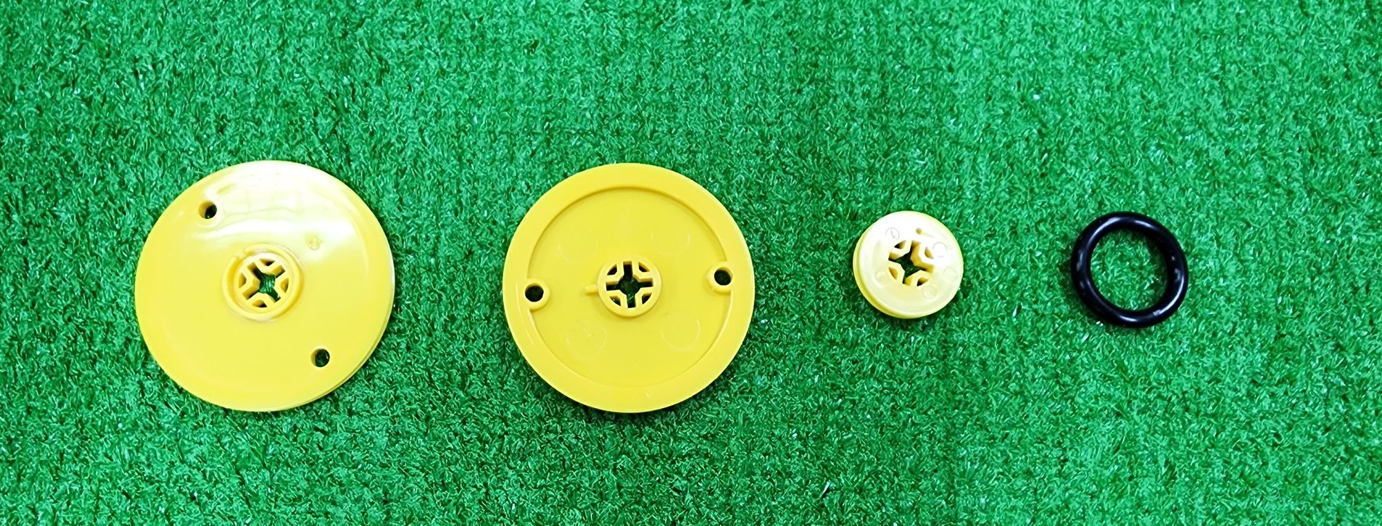
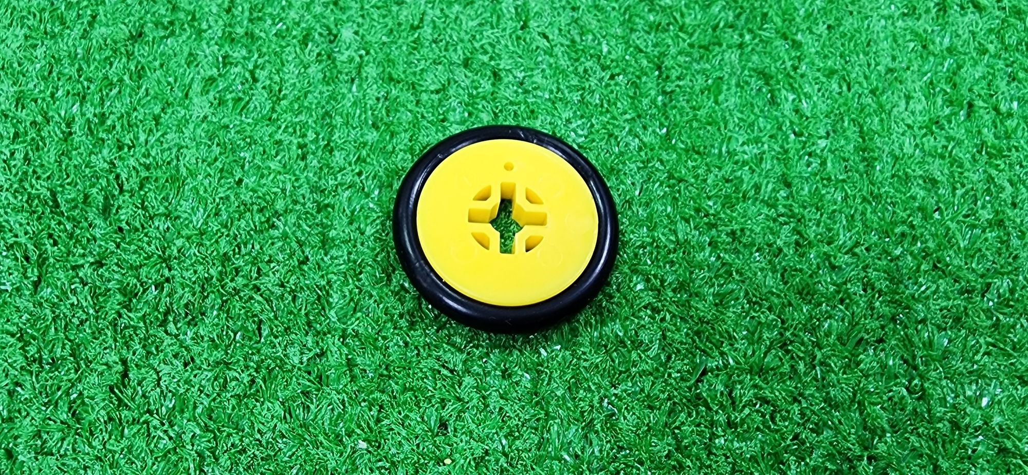
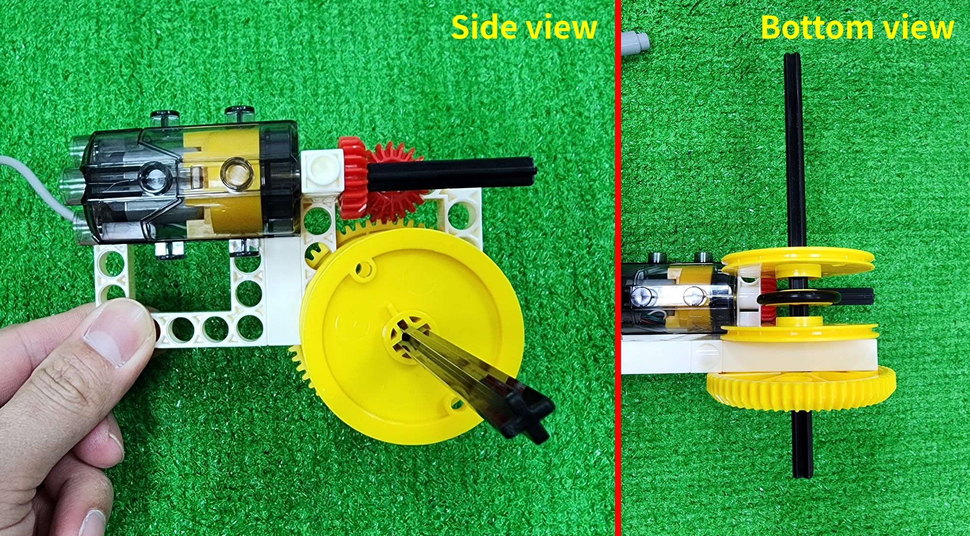
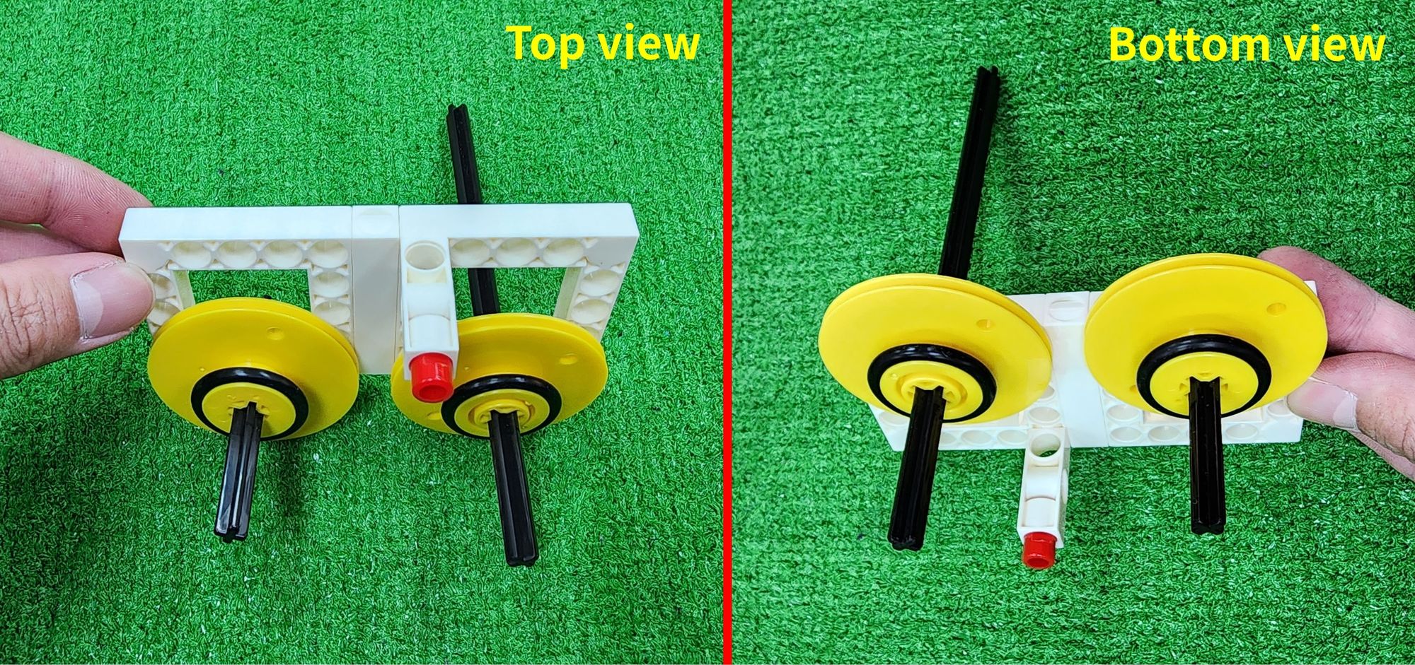
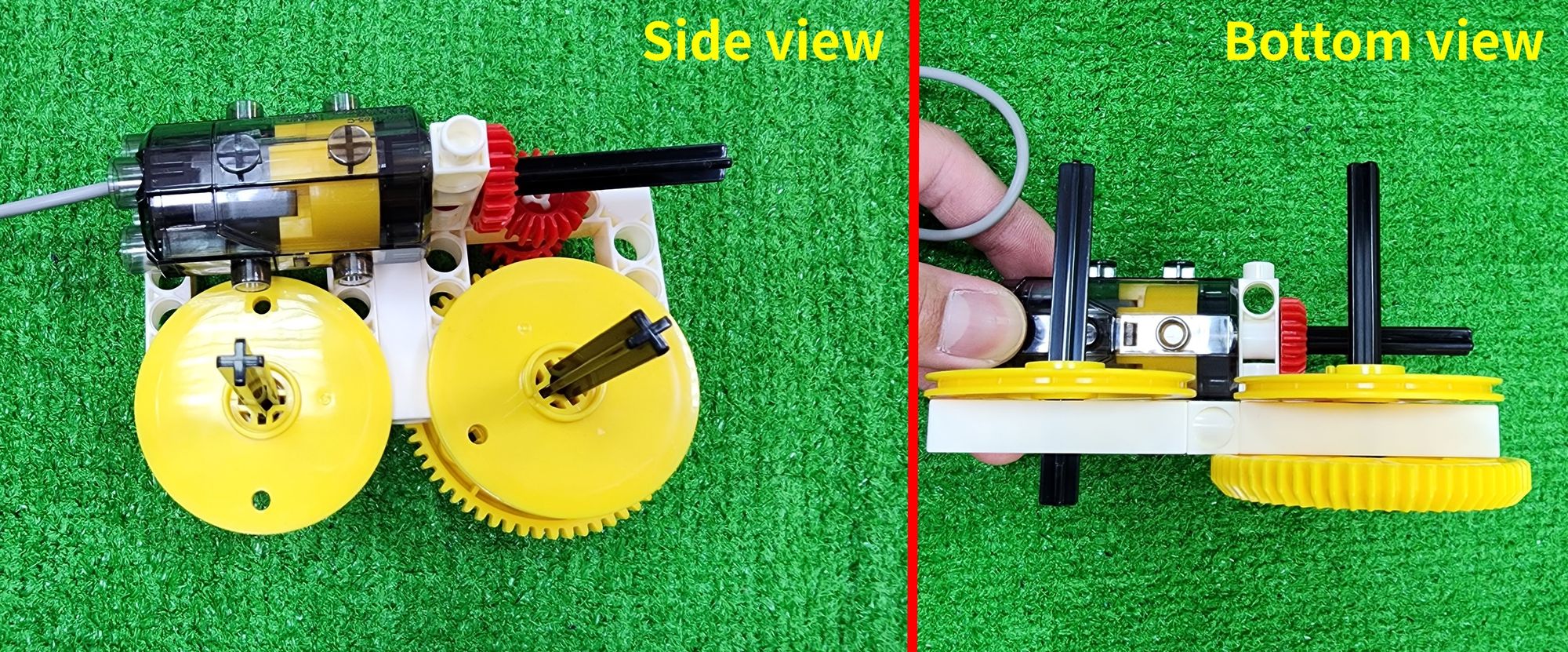
Step 21: It requires the use of C-OD53mm PULLEY, C-OD23mm PULLEY, C-OD26 O-RING, C-70mm AXLE Ⅱ, and C-70mm RUBBER BAND (Figure 78). First, similarly, place the C-OD26 O-RING around the outer edge of the C-OD23mm PULLEY (Figure 79). Then, thread the C-70mm AXLE Ⅱ through part F, and sequentially place the C-OD53mm PULLEY and C-OD23mm PULLEY onto it, ensuring that the C-OD23mm PULLEY are positioned between the two C-OD53mm PULLEY (Figure 80).
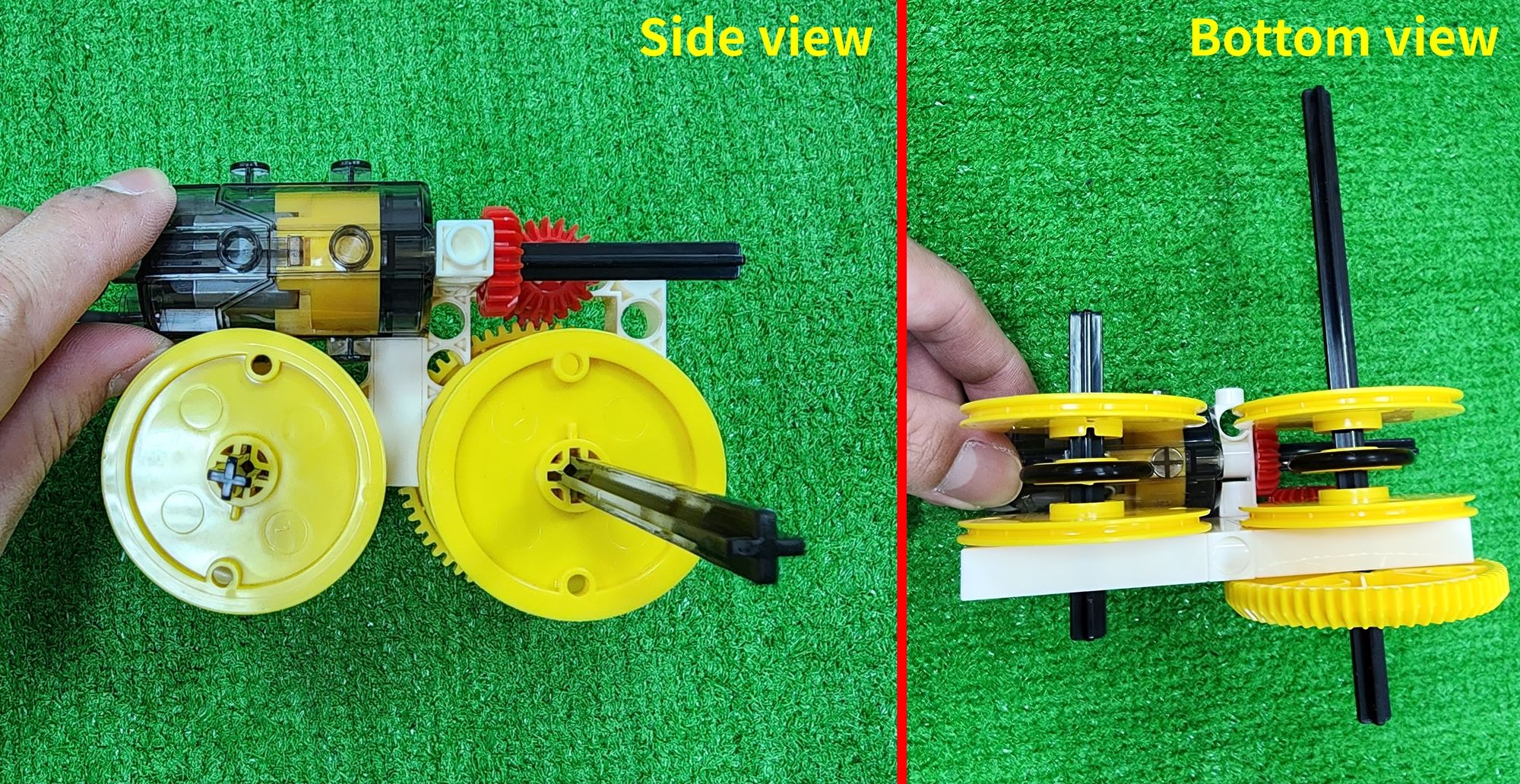
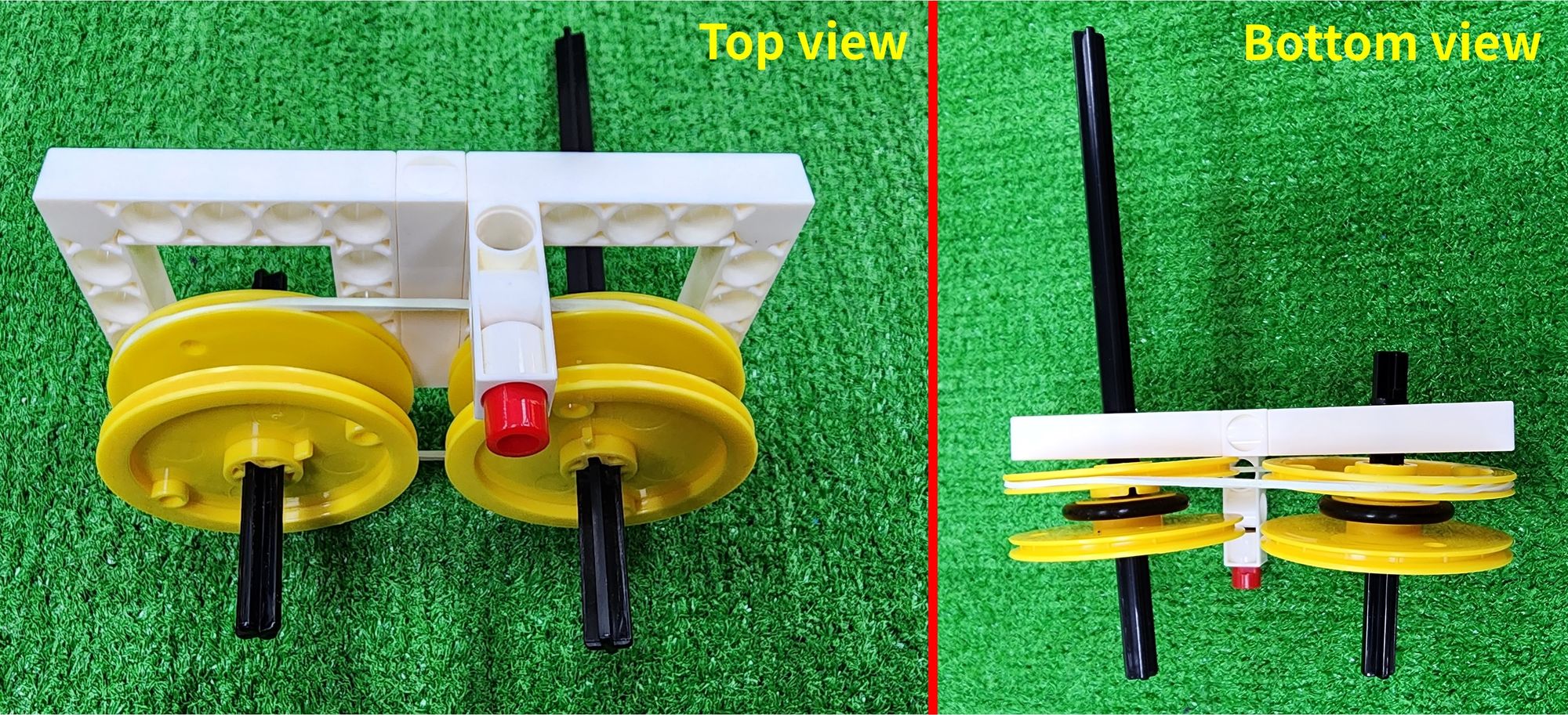
Next, place the C-70mm RUBBER BAND around the outer sides of the two C-OD53mm PULLEY closest to part F (Figure 81). When the C-150mm AXLE Ⅰ rotates, the C-70mm AXLE Ⅱ should also rotate.
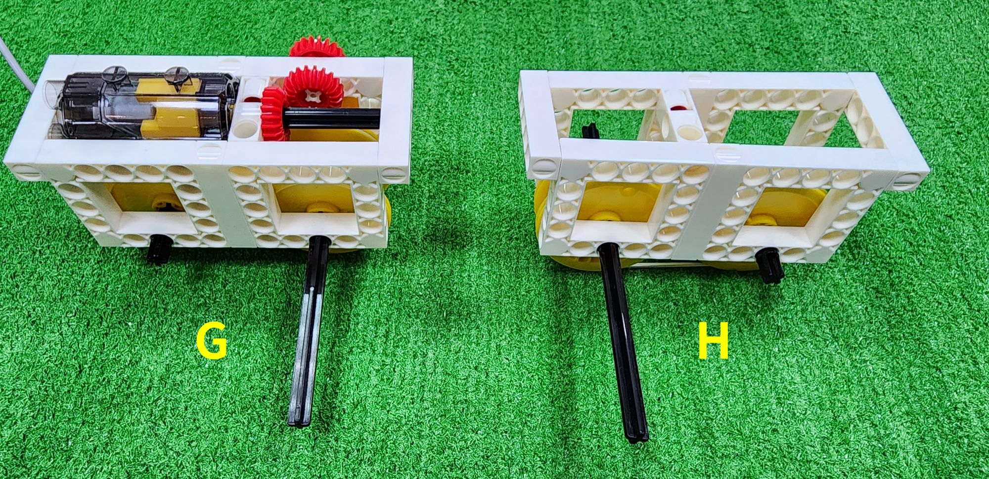
Step 22: We need to thread another part F through the C-70mm AXLE Ⅱ and the C-150mm AXLE Ⅰ, and connect it with the C-3 HOLE DUAL ROD (Figure 82). Then, connect the C-LONG PEG with the C-5 HOLE ROD (Figure 83), and install it between the two part F; thus, the assembly of part G is completed (Figure 84).

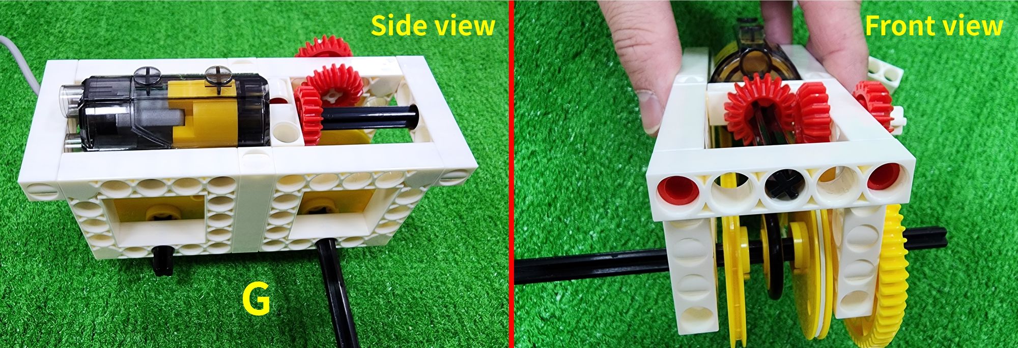
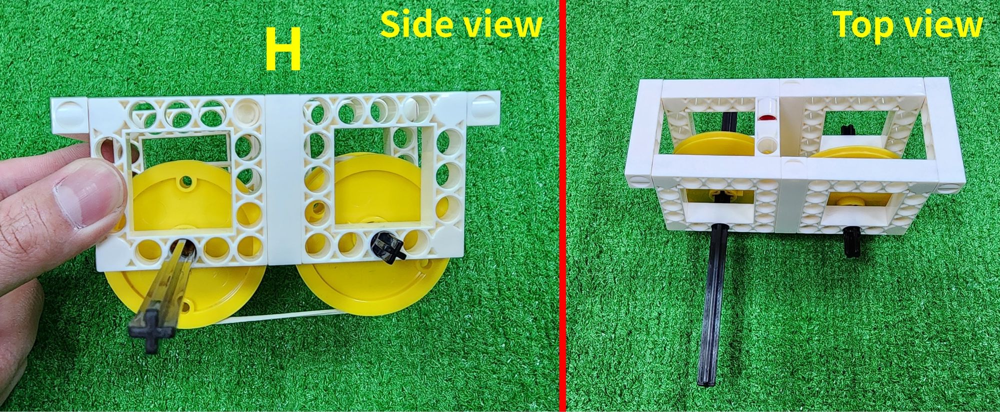
Next, we'll make part H. When the front and rear carriages move, part H will move along with part G. We'll need the C-5×5 FRAME, C-5 HOLE ROD, C-3 HOLE DUAL ROD, C-70mm AXLE Ⅱ, C-150mm AXLE Ⅰ, C-OD53mm PULLEY, C-OD23mm PULLEY, C-OD26 O-RING, C-LONG PEG, C-70mm RUBBER BAND (Figure 85).
Step 23: It is the same as step 16, where we need to connect the C-5×5 FRAME and the C-5 HOLE ROD to each other to complete two part F (Figure 86).
Step 24: We need to insert the C-LONG PEG into the C-3 HOLE DUAL ROD, and then install the C-3 HOLE DUAL ROD onto part F (Figure 87).
Step 25: We need to use C-70mm AXLE Ⅱ, C-150mm AXLE Ⅰ, and C-OD53mm PULLEY. According to the figure, insert the C-150mm AXLE Ⅰ and the C-70mm AXLE Ⅱ into part F, then place an C-OD53mm PULLEY on each side (Figure 88).
Step 26: It requires using C-OD23mm PULLEY and C-OD26 O-RING. Next, similarly, place the C-OD26 O-RING around the outer edge of the C-OD23mm PULLEY (Figure 89), and install the C-OD23mm PULLEY on the C-150mm AXLE Ⅰ and the C-70mm AXLE Ⅱ(Figure 90).
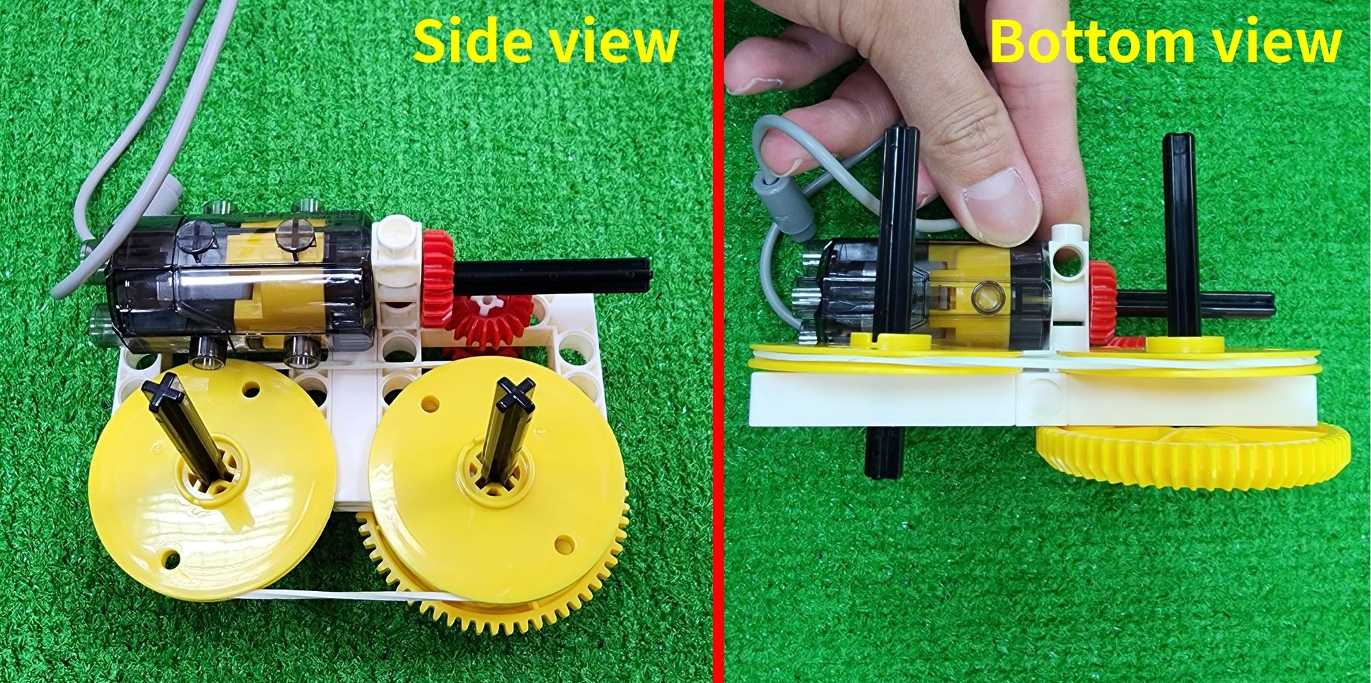
Step 27: It requires using C-OD53mm PULLEY and a C-70mm RUBBER BAND. First, install the C-OD53mm PULLEY on the C-150mm AXLE Ⅰ and the C-70mm AXLE Ⅱ (Figure 91). Then, similarly, place the C-70mm RUBBER BAND around the outer edge of the two C-OD53mm PULLEY closest to the part F, ensuring that when the C-150mm AXLE Ⅰ rotates, the C-70mm AXLE Ⅱ also rotates (Figure 92).
Step 28: We need to thread another part F through the C-70mm AXLE Ⅱ and the C-150mm AXLE Ⅰ, and connect it with a C-3 HOLE DUAL ROD (Figure 93). Then, join the C-LONG PEG with a C-5 HOLE ROD (Figure 94), and install it between the two part F. The assembly of part H is now complete (Figure 95).
Now that we've completed part F and H (Figure 96), the left and right parts of the front and rear carriage, we'll use them in the subsequent assembly steps. You can set them aside for now.
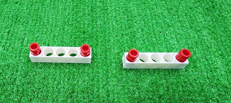
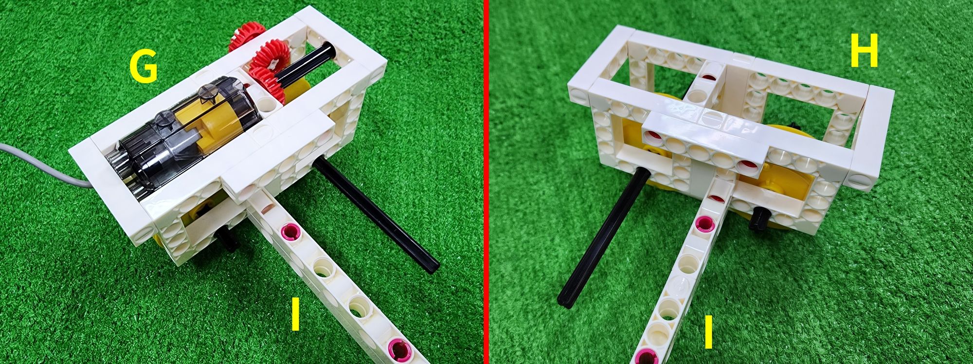
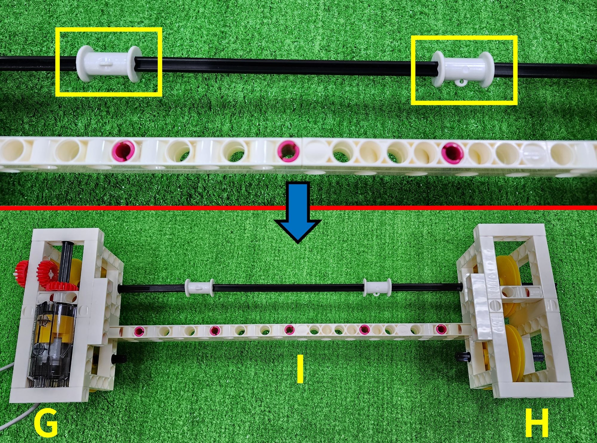
Step 29: We now make the left and right tracks (part I), utilizing the C-15 HOLE DUAL ROD, C-5 HOLE DUAL ROD, C-9 HOLE ROD FRONT CLOSED, and C-STATIC AXLE CONNECTOR (Figure 97). Initially, assemble the C-15 HOLE DUAL ROD, the C-5 HOLE DUAL ROD, and the C-9 HOLE ROD FRONT CLOSED into two separate components. Then, install the C-STATIC AXLE CONNECTOR on one of the components (Figure 98).
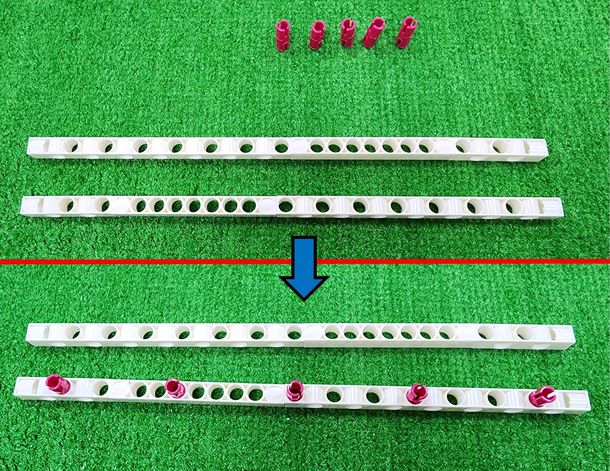
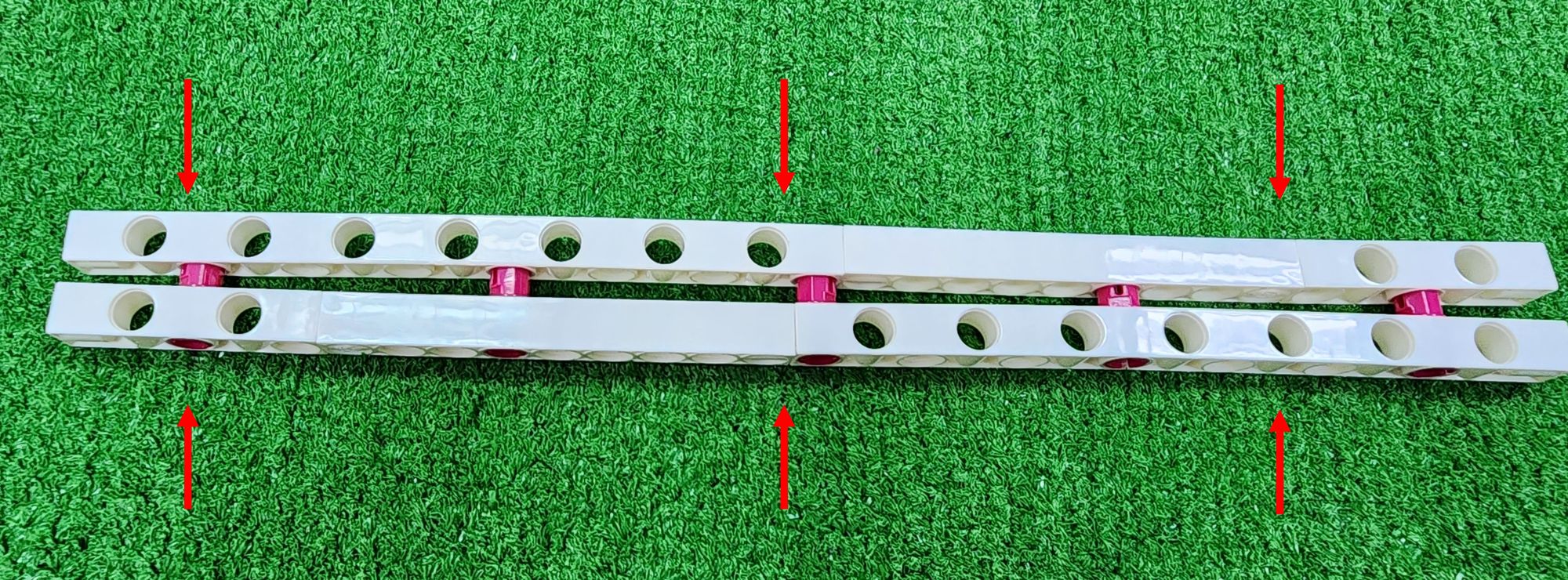
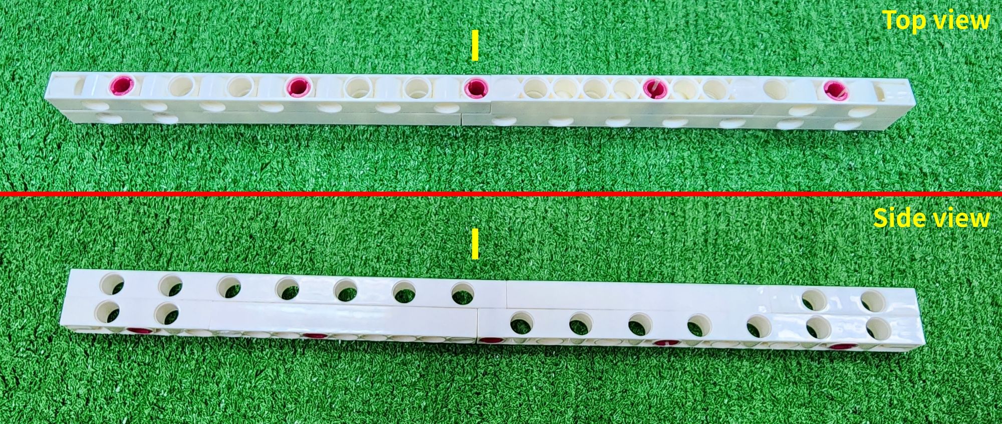
Next, we overlap the two components and press them inward, fastening them together using the C-STATIC AXLE CONNECTOR (Figure 99). This completes part I, which is the left and right tracks (Figure 100).
Finally, we will assemble the front and rear carriages, requiring part G, H, and I, along with the C-150mm AXLE Ⅰ, C-5 HOLE ROD, C-ROLLER (7900-W10-H1SK), and C-LONG PEG (Figure 101).
Step 30: We now use the C-LONG PEG and C-5 HOLE ROD. First, install the C-LONG PEG on part G and H (Figure 102) Then, connect the C-5 HOLE ROD to the C-LONG PEG (Figure 102).
Step 31: We need to connect the left and right ends of part I with the C-LONG PEG on part G and H (Figure 104). After completion, the overall structure of the front and rear carriages is shown in picture (Figure 105).
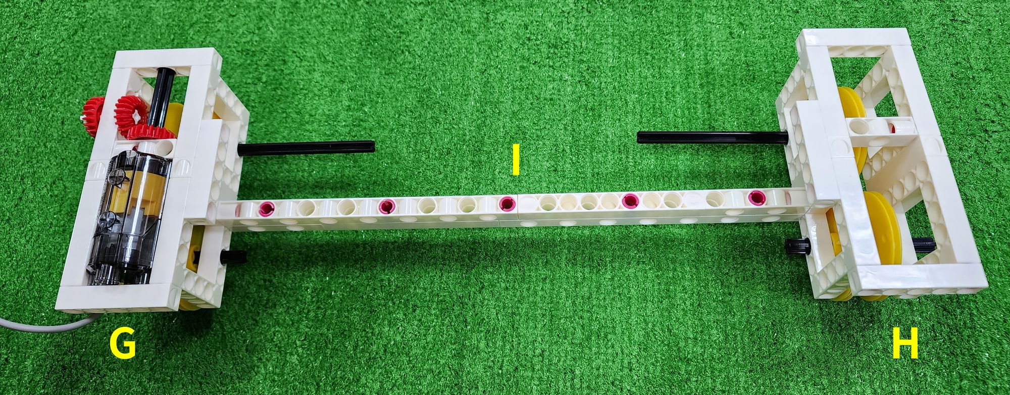
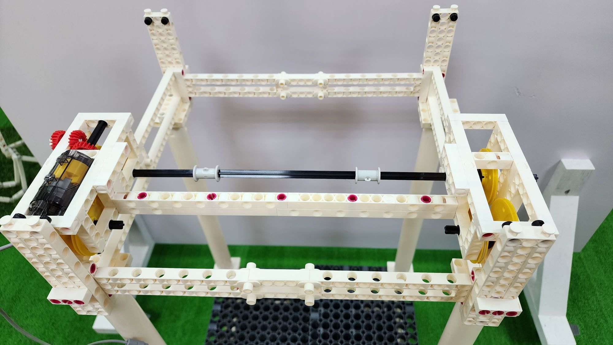
Step 32: We need to use the C-150mm AXLE Ⅰ and the C-ROLLER to connect the three C-150mm AXLE Ⅰ together. You can start by pushing the C-150mm AXLE Ⅰ on part G and H outward, leaving some space to place the middle C-150mm AXLE Ⅰ. Once the middle C-150mm AXLE Ⅰ is placed, push the C-150mm AXLE Ⅰ on part G and H inward and insert them into the C-ROLLER. This completes the assembly of the front and rear carriages (Figure 106).
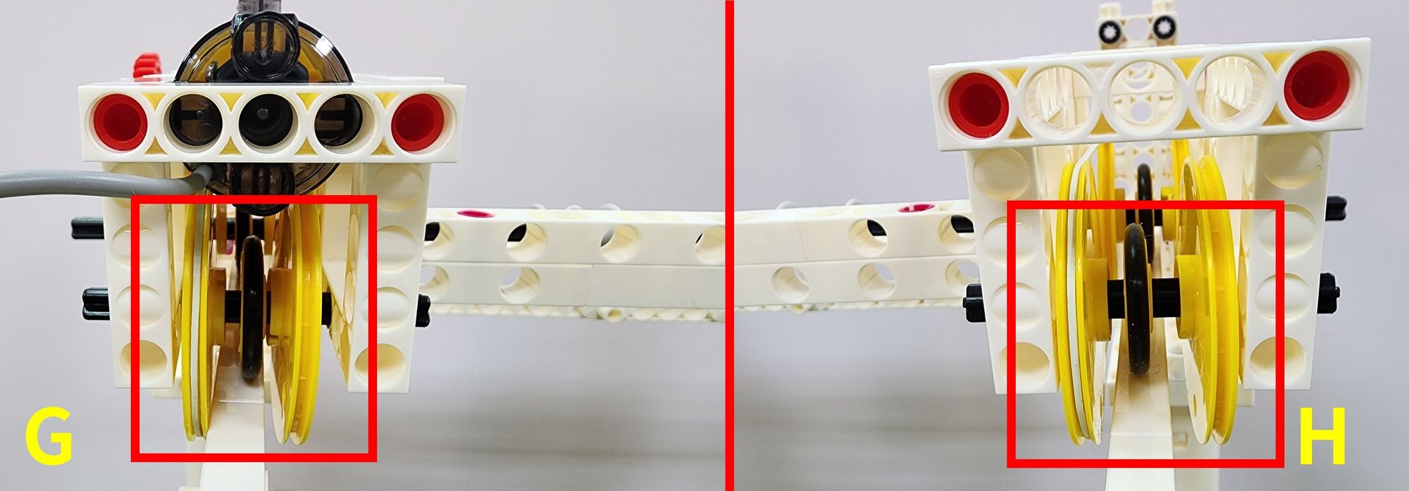
Step 33: We need to place the entire front and rear carriages on the front and rear tracks (Figure 107). After placing them, ensure that the C-OD26 O-RING on part G and H make full contact with the front and rear tracks, and adjust the spacing between the C-OD53mm PULLEY on part G and H (Figure 108). If the spacing between the C-OD53mm PULLEY is too large, it may cause shaking when the front and rear carriages move. If the spacing is too small, it may lead to wear between the C-OD53mm PULLEY and the front and rear tracks, affecting the speed of movement of the front and rear carriages.
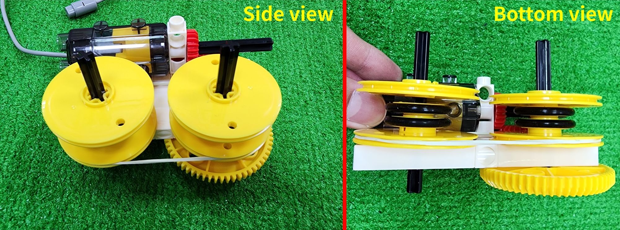
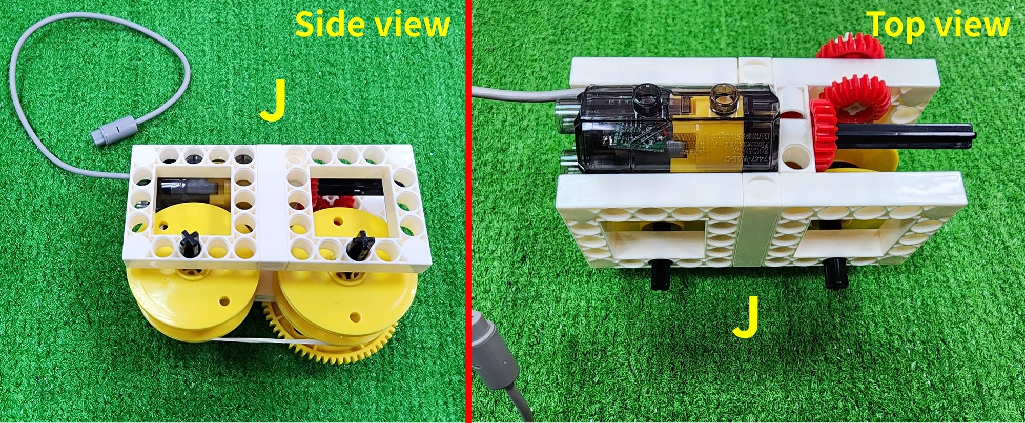
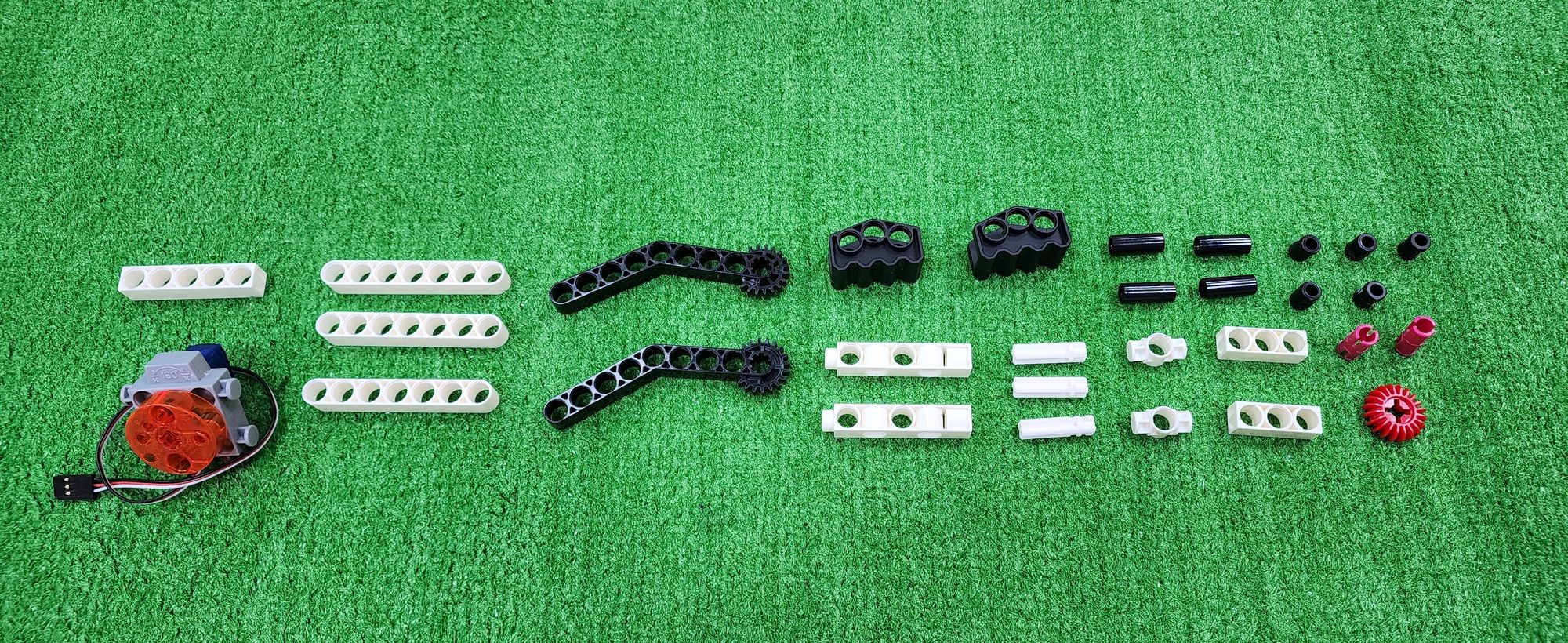
Now we're going to make the left and right carriages (Part J) for the claw machine. These carriages will travel above the left and right tracks, allowing the claw to move horizontally. We'll primarily use C-5×5 FRAME, C-5 HOLE ROD, C-3 HOLE DUAL ROD, C-70mm AXLE Ⅱ, C-MOTOR AXLE, C-20T GEAR, C-60T GEAR, C-OD53mm PULLEY, C-OD23mm PULLEY, C-OD26 O-RING, C-LONG PEG, C-70mm RUBBER BAND, and a C-50X PLANETARY GEARBOX (Figure 109).
First, refer to the process outlined in step 16 to complete two Part F units (Figure 110). Then, follow the steps from 17 to 18 to install the C-50X PLANETARY GEARBOX onto Part F (Figure 111).
Step 34: We need to use a C-70mm AXLE Ⅱ and a C-60T GEAR. First, install the C-60T GEAR onto the C-70mm AXLE Ⅱ (Figure 112), then insert the C-70mm AXLE Ⅱ into the holes of Part F as shown (Figure 113).
Next, we'll need the C-70mm AXLE Ⅱ, C-OD53mm PULLEY, C-OD23mm PULLEY, C-OD26 O-RING, and C-70mm RUBBER BAND (Figure 114).
Step 35: We'll need the C-70mm AXLE Ⅱ and the C-OD53mm PULLEY. Insert the C-70mm AXLE Ⅱ into Part F as shown, then place one C-OD53mm PULLEY on each side (Figure 115).
Step 36: We need the C-70mm RUBBER BAND. Put it around the outside of both C-OD53mm PULLEY as shown (Figure 116), ensuring that when one of the C-70mm AXLE Ⅱ rotates, the other one rotates along with it.
Step 37: We'll need the C-OD23mm PULLEY and C-OD26 O-RING. Place the C-OD26 O-RING around the outer edge of the C-OD23mm PULLEY as shown (Figure 117), then install the C-OD23mm PULLEY onto the C-70mm AXLE Ⅱ (Figure 118).
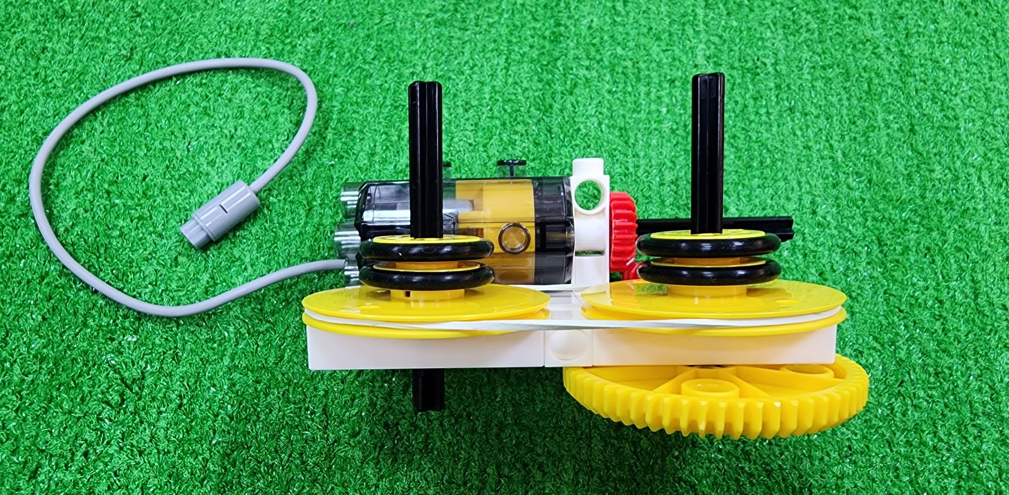
Step 38: We need to use the C-OD53mm PULLEY and install it onto the C-70mm AXLE Ⅱ as shown (Figure 119). This completes the assembly of the left and right carriages (Part J) (Figure 120).
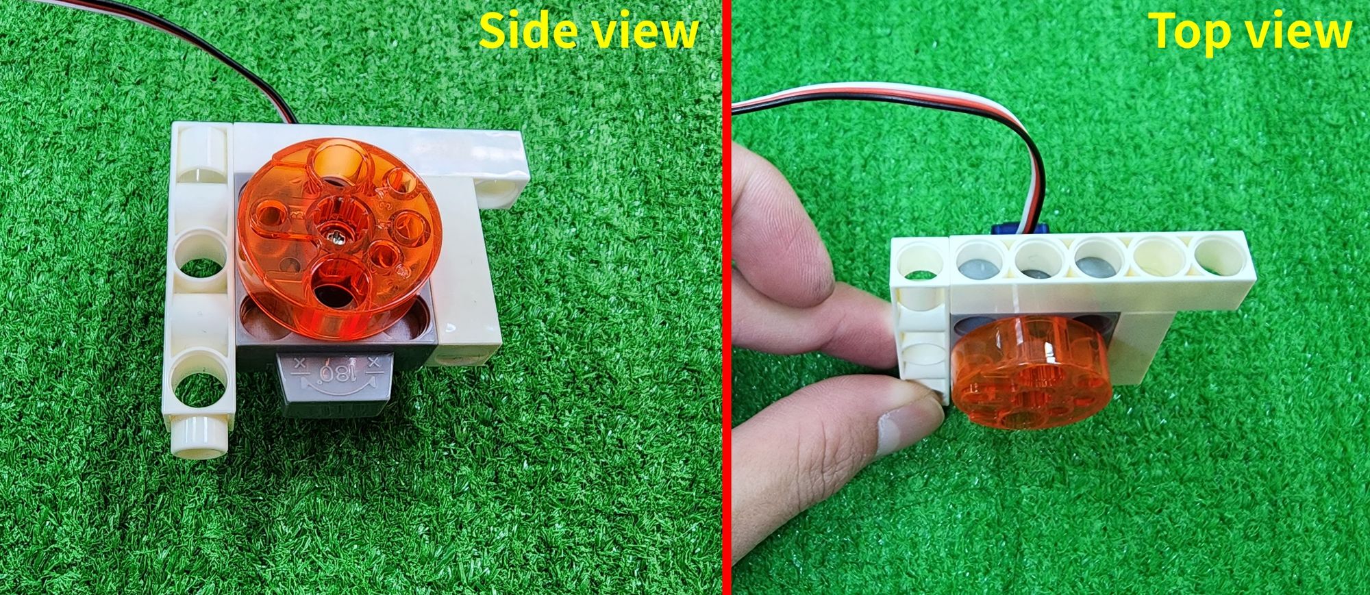
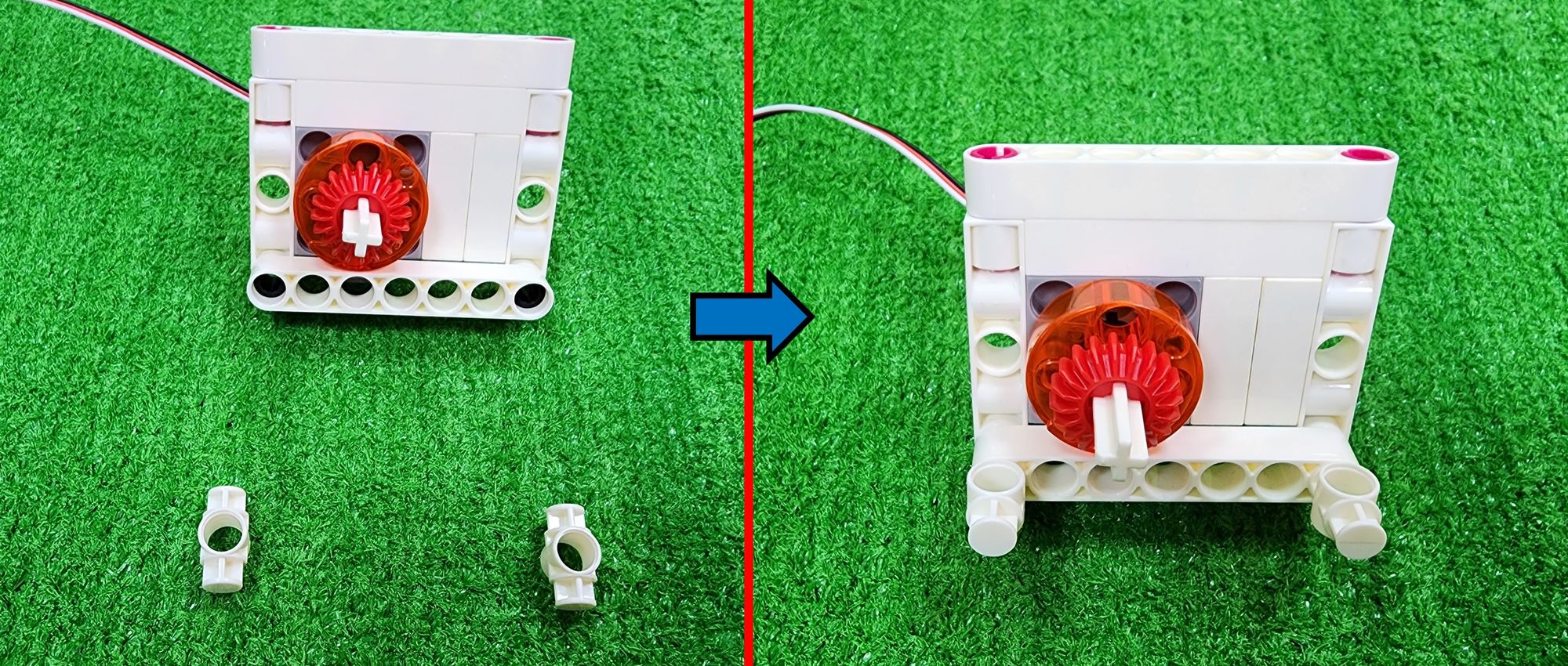
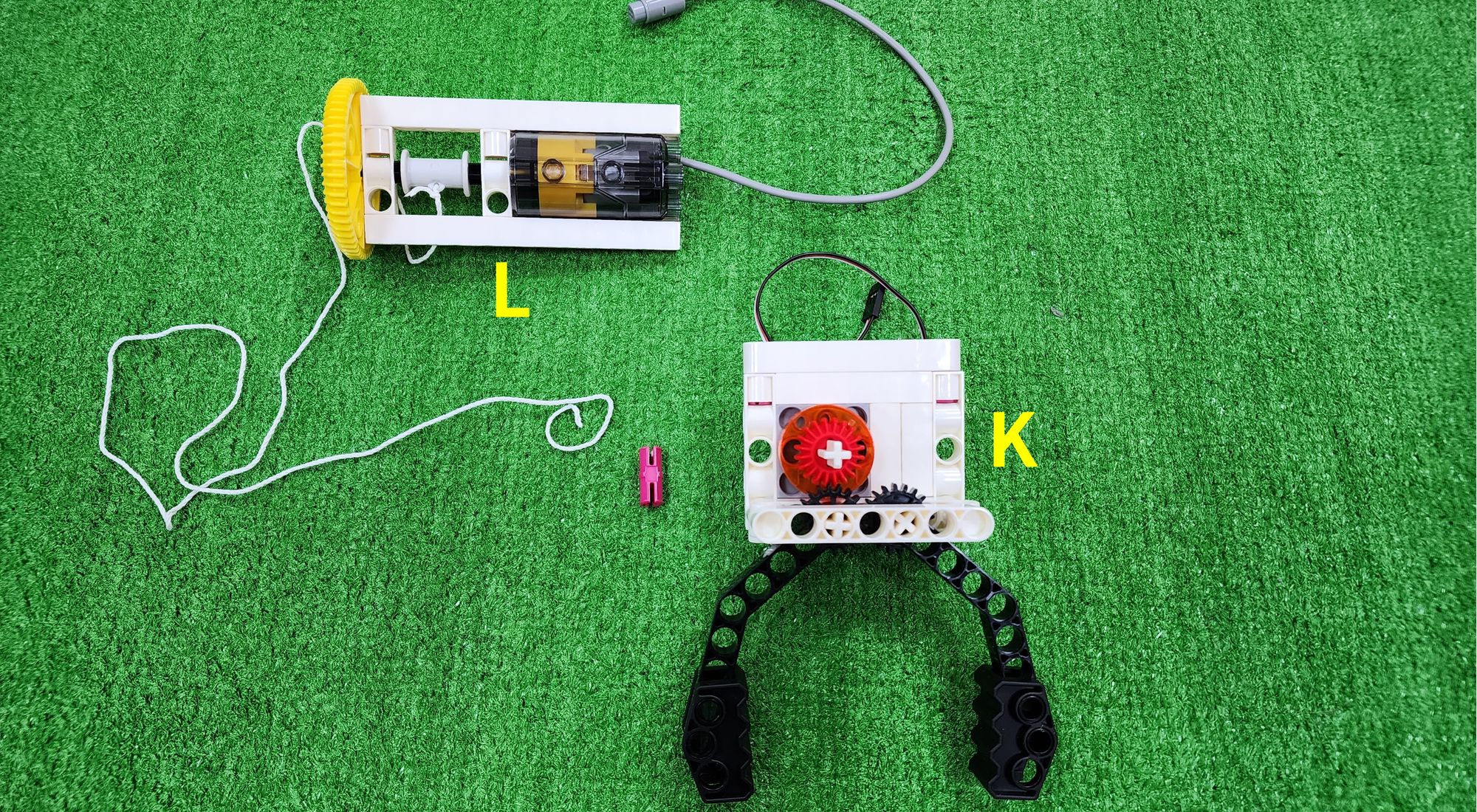
Now we're going to make the claw (Part K) of the claw machine. The claw can open and close using a C-180° SERVO MOTOR to grasp objects. We'll primarily use a C-7 HOLE ROUND ROD, C-GRIPPER (7411-W10-G1D), C-5 HOLE DUAL ROD, C-5 HOLE ROD, C-3 HOLE ROD, C-MOTOR AXLE, a C-145°CRANKSHAFT GEAR-A (7411-W10-C1D), a C-145°CRANKSHAFT GEAR-B (7411-W10-C2D), a C-20T GEAR, a C-20mm OD8 TUBE (7400-W10-G2D), B-SHORT PEG, C-STATIC AXLE CONNECTOR, C-1 HOLE CONNECTOR (7430-W10-B1W), and a C-180° SERVO MOTOR (Figure 121).
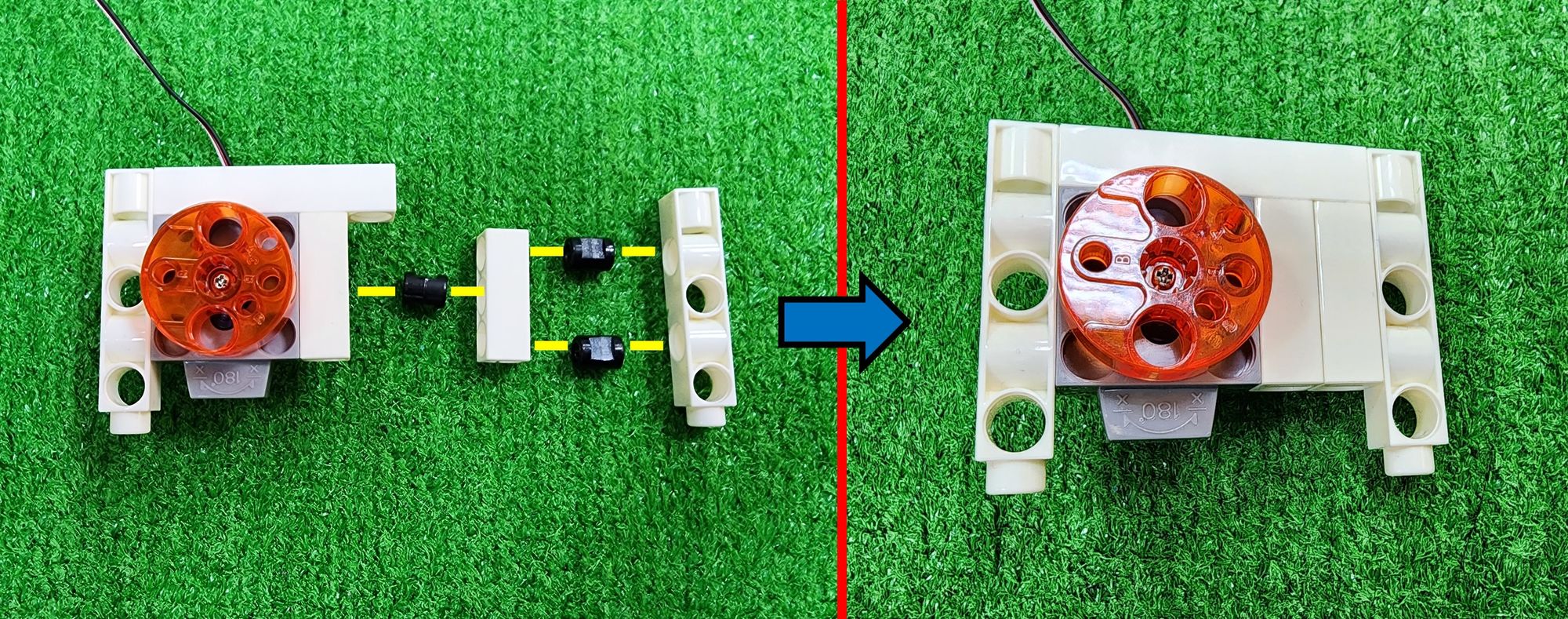
Step 39: We need to use the C-180° SERVO MOTOR along with a C-5 HOLE DUAL ROD, a C-5 HOLE ROD, and a C-3 HOLE ROD. Following the figure, we'll mount each rod onto the C-180° SERVO MOTOR (Figure 122).
Step 40: We'll need a C-5 HOLE DUAL ROD, a C-3 HOLE ROD, and a B-SHORT PEG. Using the B-SHORT PEG, we'll connect the C-5 HOLE DUAL ROD and the C-3 HOLE ROD. Then, we'll use another B-SHORT PEG to mount them onto the C-3 HOLE ROD (Figure 123).
Step 41: We'll need a C-7 HOLE ROUND ROD, a C-STATIC AXLE CONNECTOR, and B-SHORT PEG. Following the figure, we'll use the C-STATIC AXLE CONNECTOR and the B-SHORT PEG to secure the C-7 HOLE ROUND ROD onto the claw, reinforcing the basic structure (Figure 124).
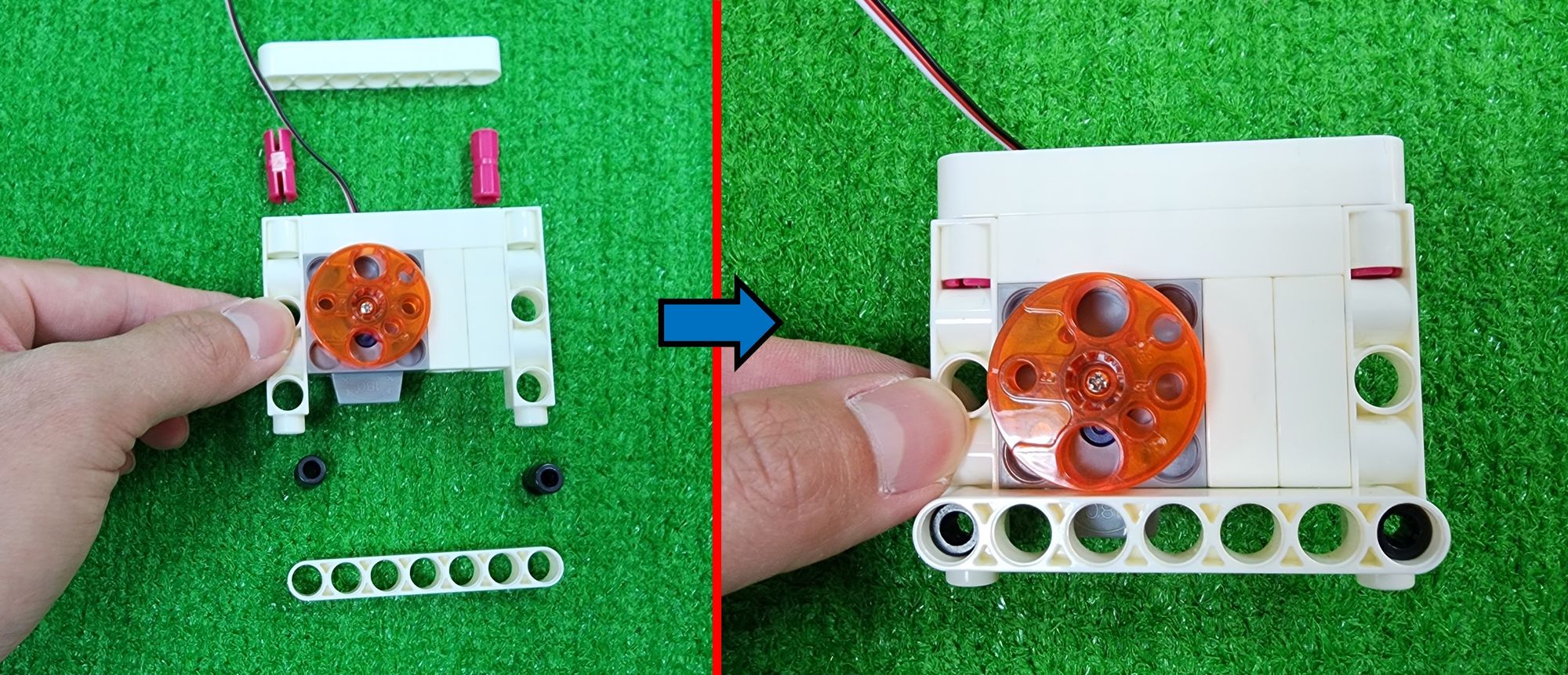
Step 42: We'll need a C-MOTOR AXLE, a C-20T GEAR, and two C-1 HOLE CONNECTOR. First, insert the C-MOTOR AXLE through the C-20T GEAR and into the C-180° SERVO MOTOR (Figure 125). Then, following the figure, install the two C-1 HOLE CONNECTOR onto the claw (Figure 126).
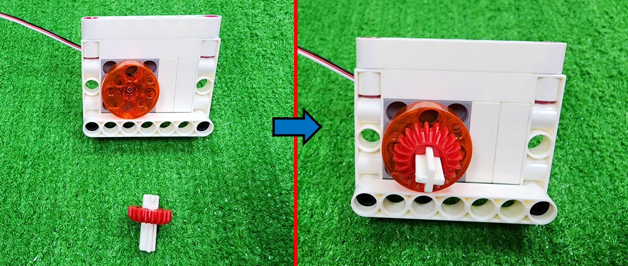
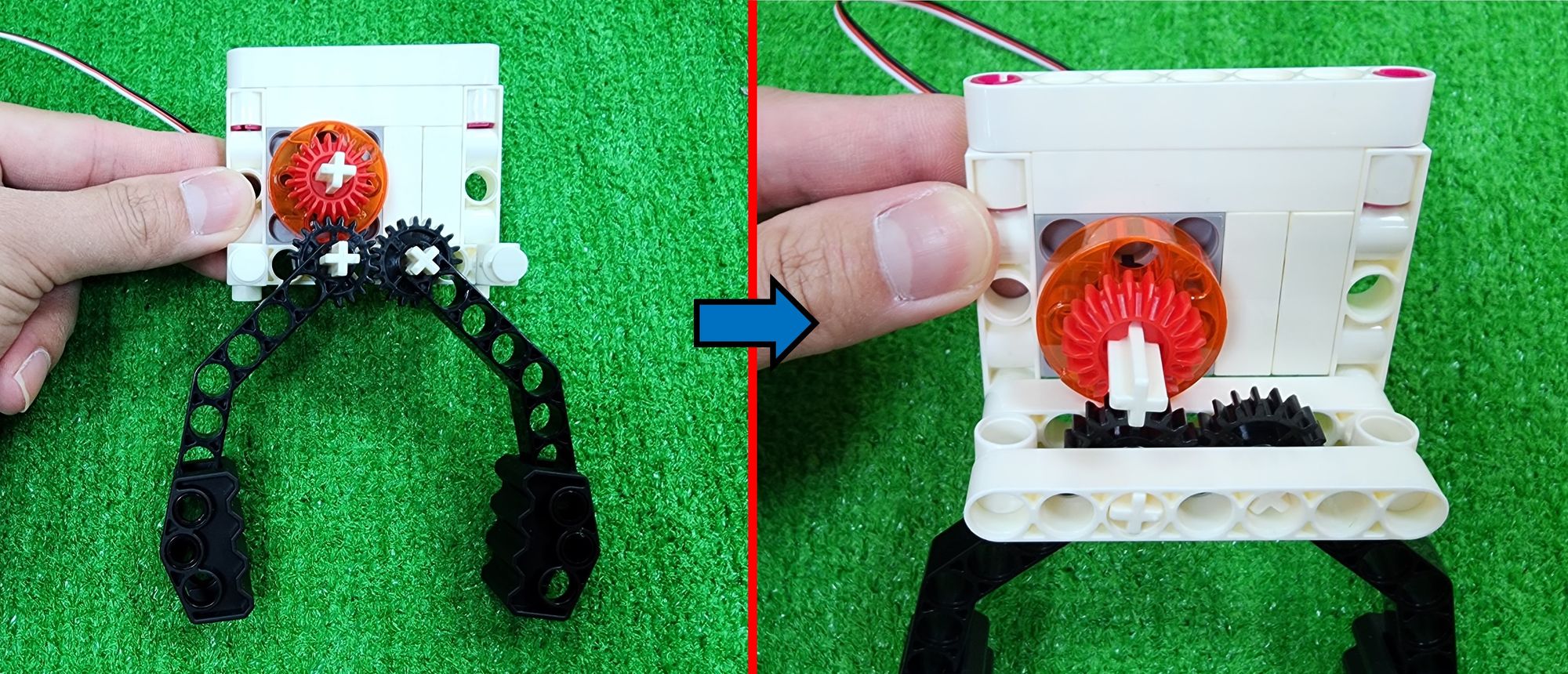
Step 43: We need to use a C-MOTOR AXLE, C-145°CRANKSHAFT GEAR-A (7411-W10-C1D), a C-145°CRANKSHAFT GEAR-B (7411-W10-C2D), C-GRIPPER (7411-W10-G1D), and C-20mm OD8 TUBE (7400-W10-G2D). First, thread the C-MOTOR AXLE and the C-20mm OD8 TUBE through the C-145°CRANKSHAFT GEAR-A and C-145°CRANKSHAFT GEAR-B respectively. Then, following the figure, install the C-GRIPPER onto the C-20mm OD8 TUBE (Figure 127).
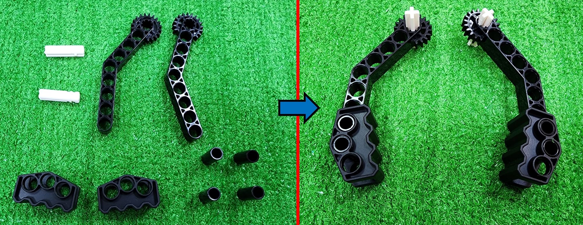
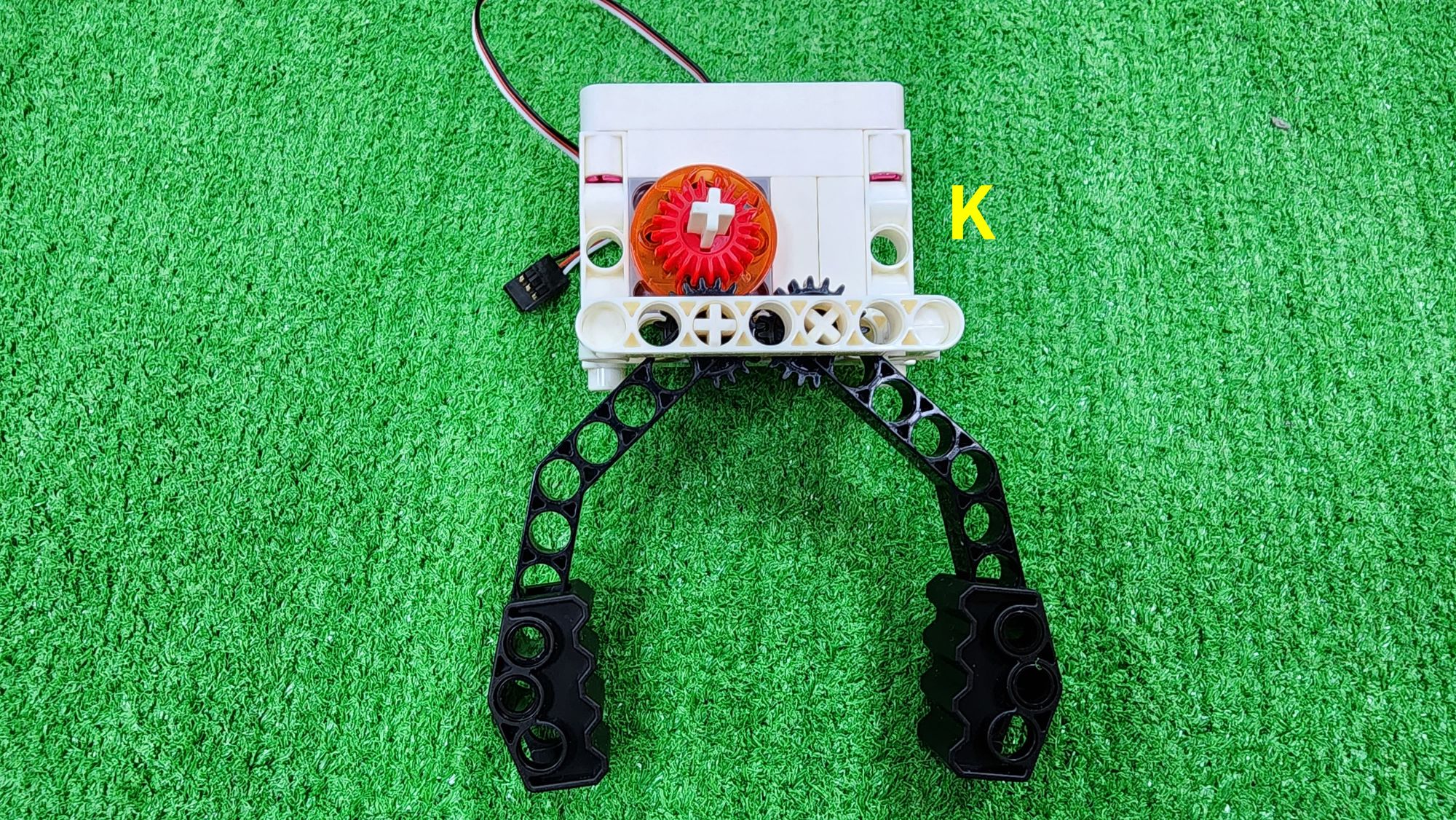
Step 44: We need to use a C-7 HOLE ROUND ROD. First, following the figure, install the C-MOTOR AXLE of the C-145°CRANKSHAFT GEAR-A and C-145°CRANKSHAFT GEAR-B onto the claw. After ensuring that the C-20T GEAR, C-145°CRANKSHAFT GEAR-A and C-145°CRANKSHAFT GEAR-B are properly meshed, then install the C-7 HOLE ROUND ROD onto the claw (Figure 128), completing the production of the claw (Part K) (Figure 129).
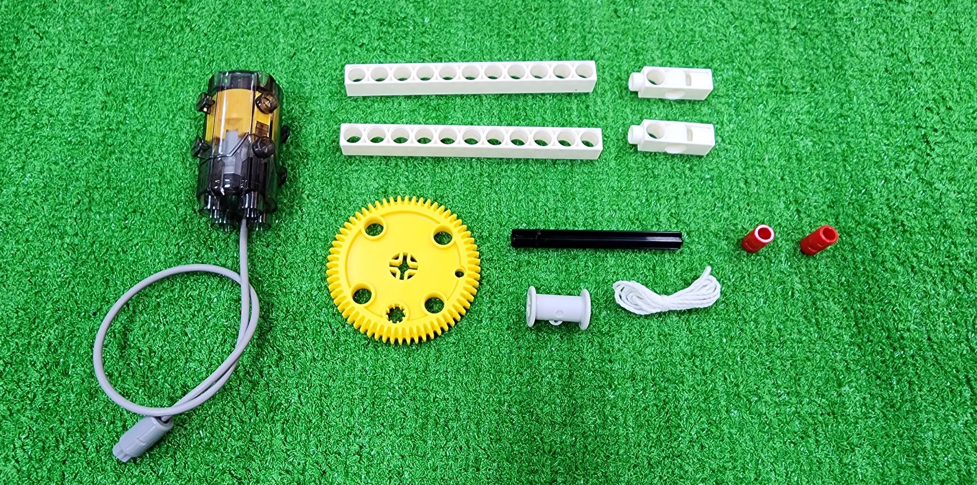
Now we're going to make the coil winding device (Part L) for the claw machine. This device adjusts the height of the claw by rotating with the C-50X PLANETARY GEARBOX, allowing the claw to move up and down. We'll mainly use a C-11 HOLE ROD, C-3 HOLE DUAL ROD, C-70mm AXLE Ⅱ, a C-60T GEAR, C-ROLLER, C-LONG PEG, cotton rope, and C-50X PLANETARY GEARBOX (Figure 130).
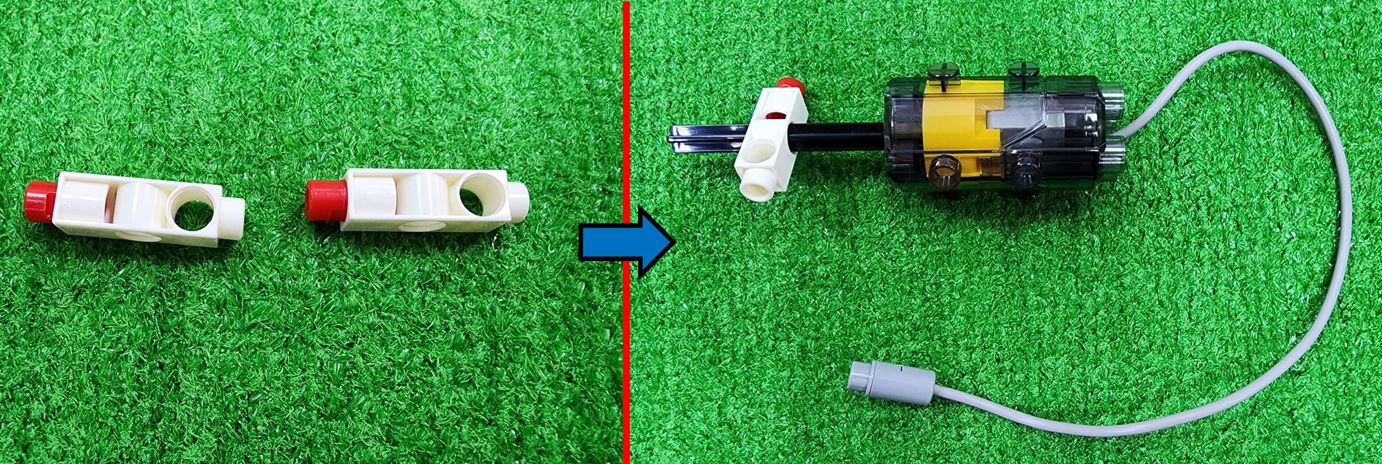
Step 45: First, insert the C-70mm AXLE Ⅱ into the C-50X PLANETARY GEARBOX, then fit it into a C-3 HOLE DUAL ROD with a C-LONG PEG (Figure 131).
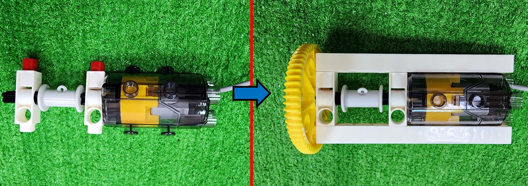
Step 46: We need to sequentially slide the C-ROLLER and a C-3 HOLE DUAL ROD with a C-LONG PEG onto the C-70mm AXLE Ⅱ, then reinforce it with an C-11 HOLE ROD. Finally, insert the C-60T GEAR onto the C-70mm AXLE Ⅱ (Figure 132).
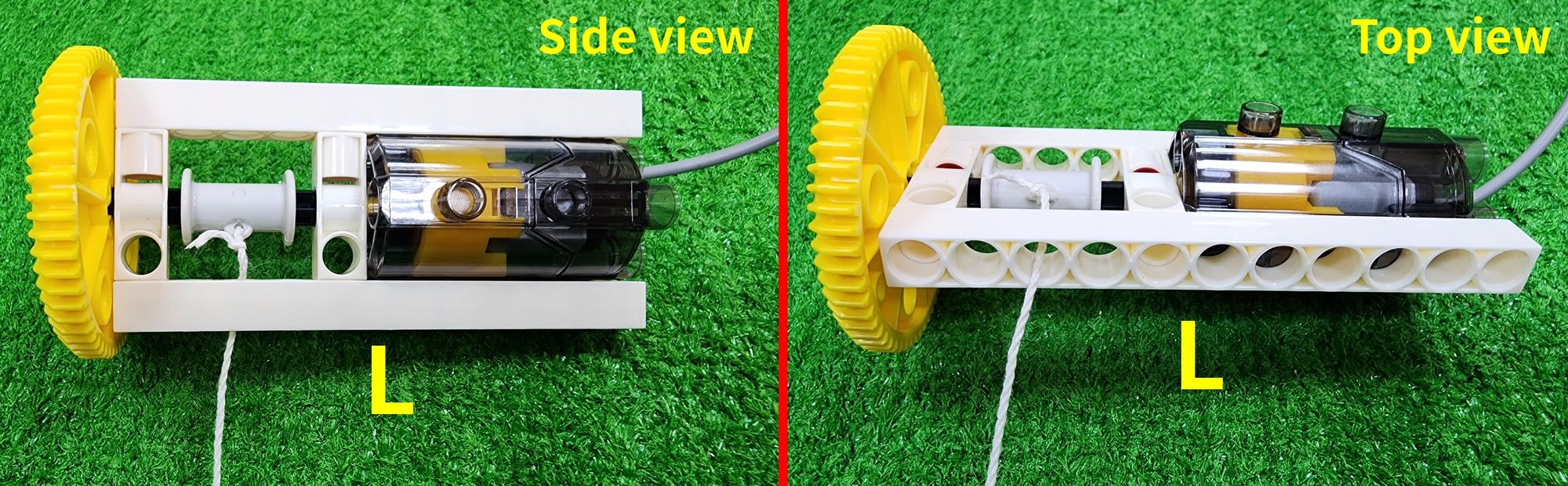
Step 47: We'll use cotton rope, tying one end to the hole in the C-ROLLER, and ensuring the other end passes through the hole in the C-11 HOLE ROD, completing the coil device (Part L) assembly (Figure 133).
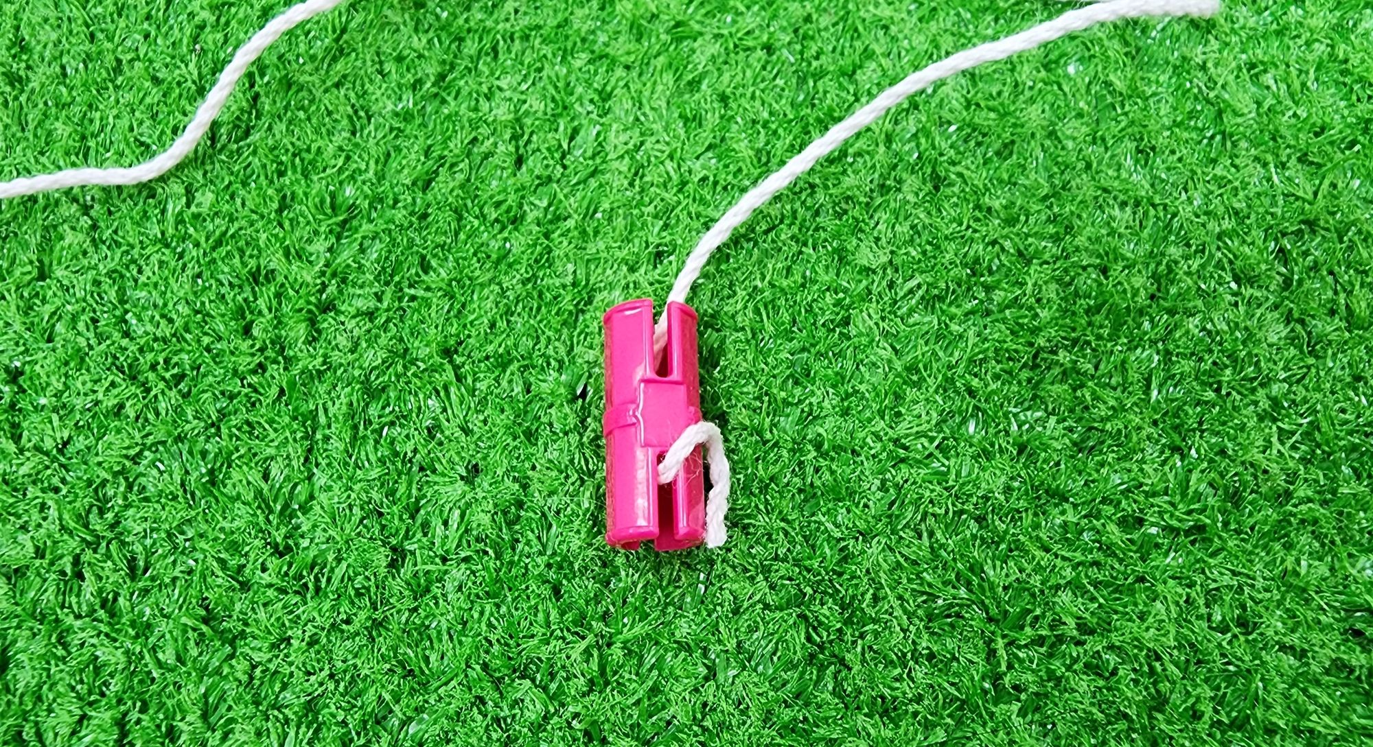
Step 48: We need to combine the claw (part K) with the coiling device (part L), and for this, we will need to use a C-STATIC AXLE CONNECTOR (Figure 134).
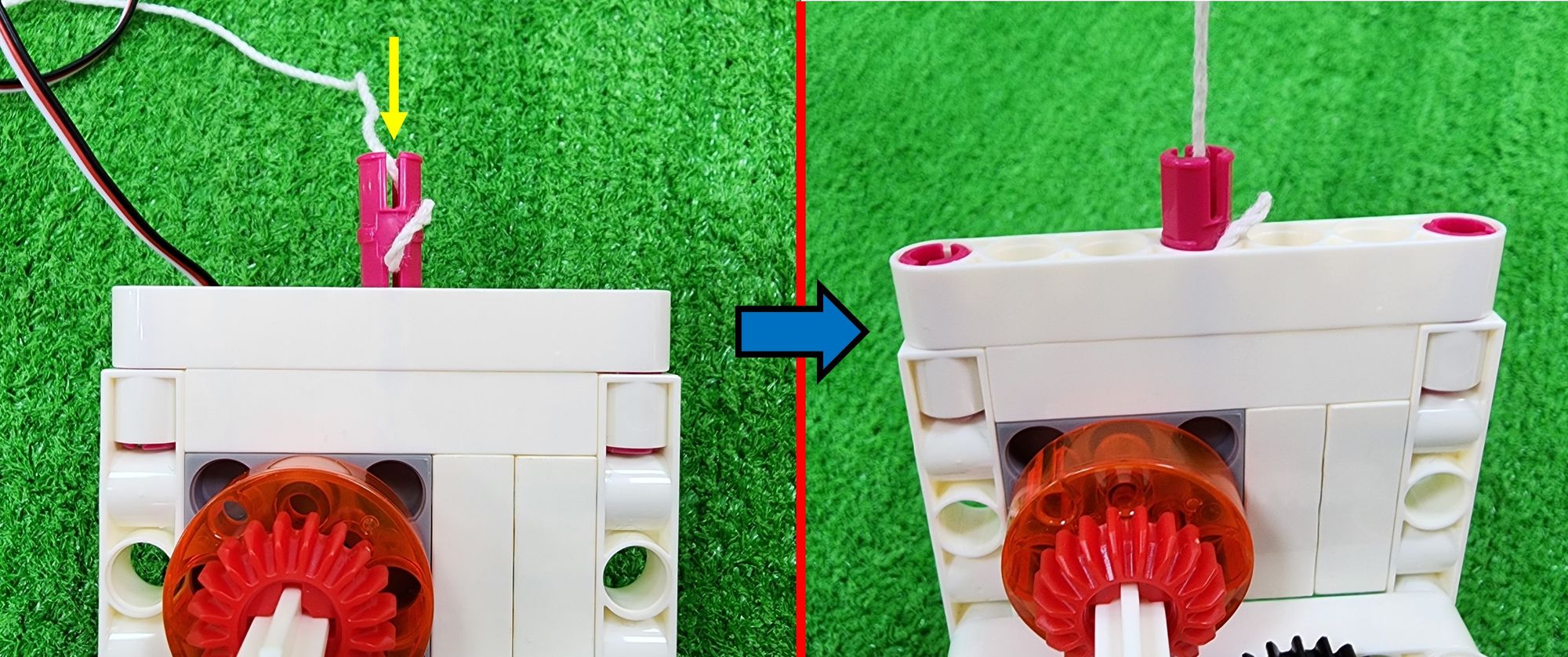
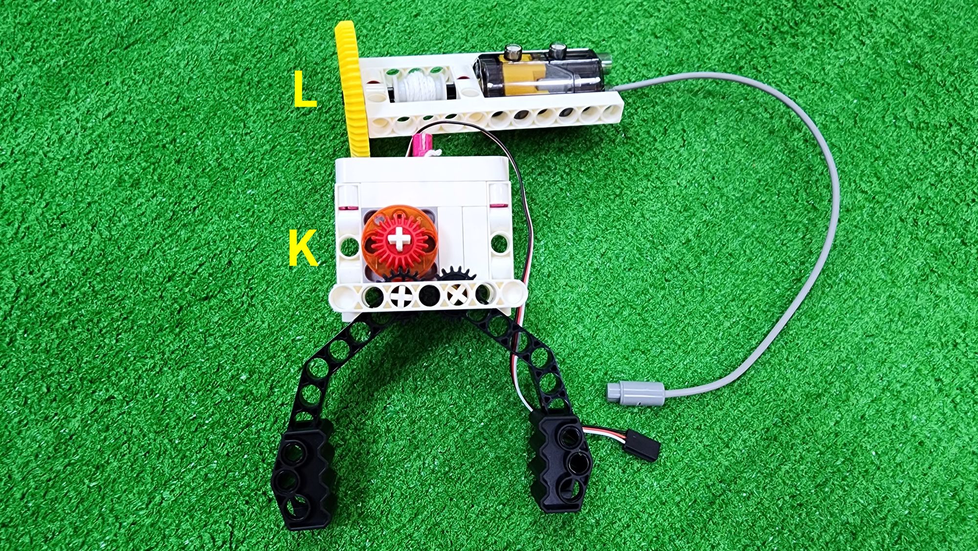
First, thread one end of the cotton rope through the groove underneath the C-STATIC AXLE CONNECTOR, leaving a small length protruding (Figure 135). Then, install the C-STATIC AXLE CONNECTOR above the claw (Figure 136). Finally, you can rotate the C-60T GEAR to wind up the cotton rope using the C-ROLLER, completing the connection between the claw (part K) and the coiling device (part L) (Figure 137).
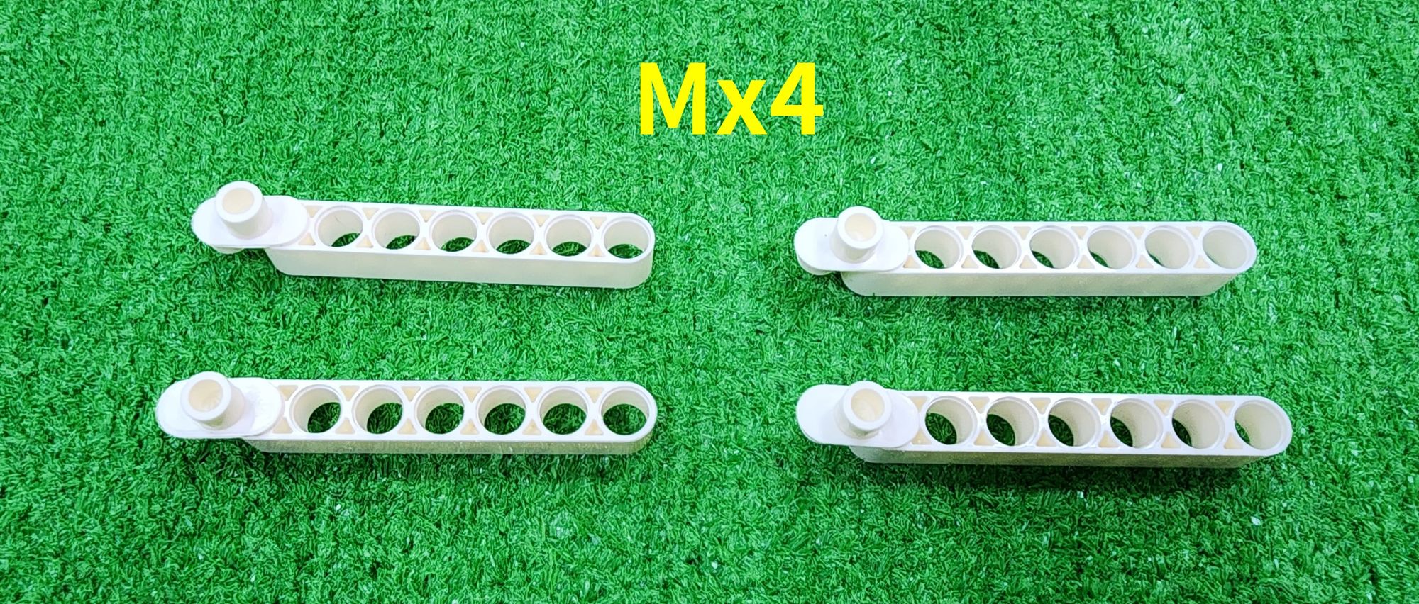
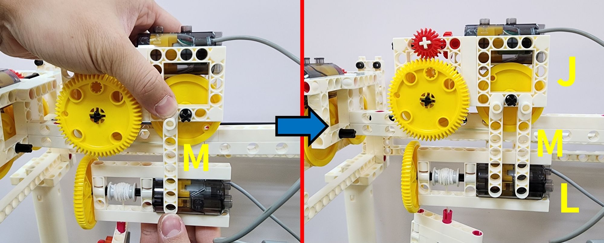
Now we are going to combine the left and right carriages (part J) with the coiling device (part L), and for this, we will need to use the C-7 HOLE ROUND ROD and C-TWO-IN-ONE CONVERTER (Figure 138).
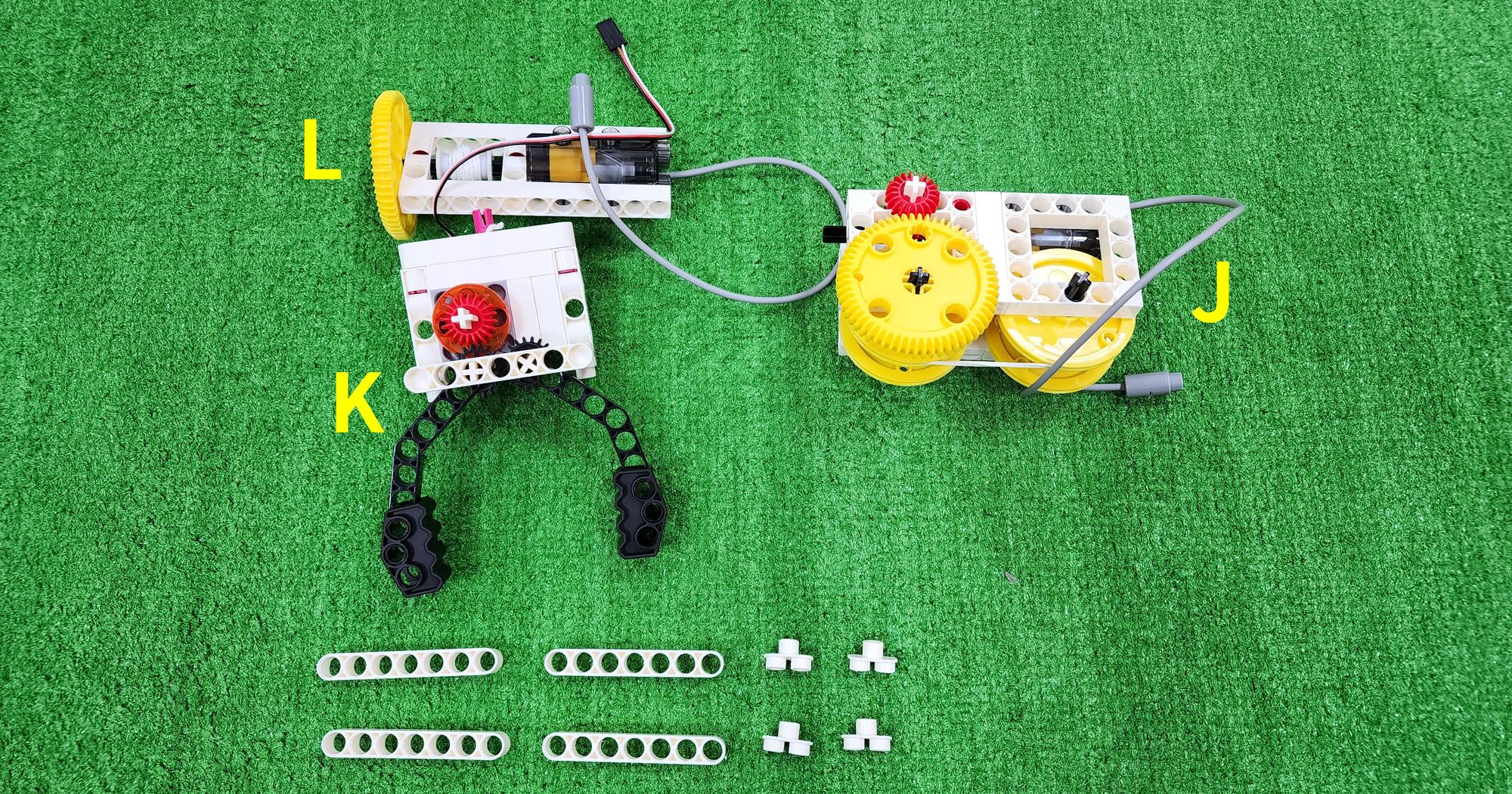
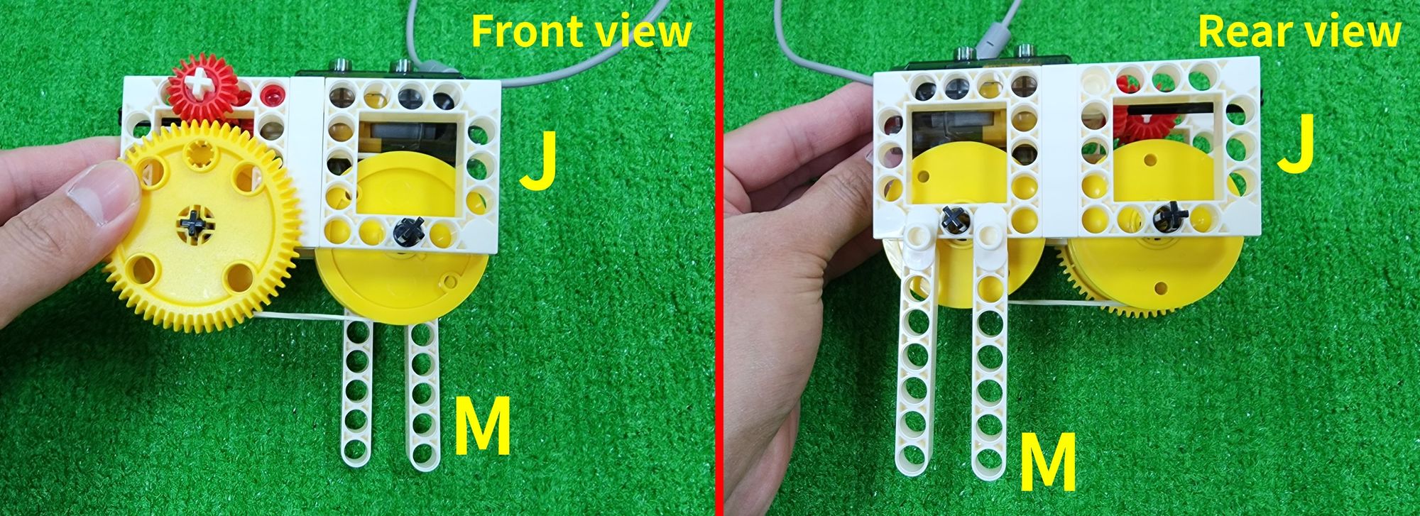
Step 49: We need to combine the C-7 HOLE ROUND ROD with the C-TWO-IN-ONE CONVERTER to complete four part M (Figure 139). Then, install the two part M behind the left and right carriages (part J) (Figure 140).
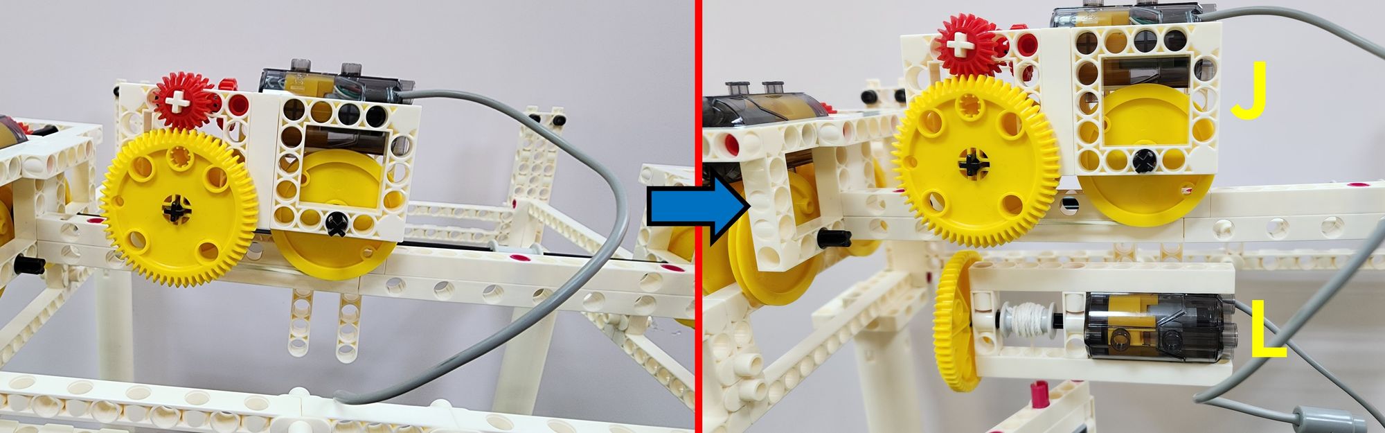
Step 50: We need to place the left and right carriages (part J) above the left and right tracks (part I), ensuring that the C-OD26 O-RING on the left and right carriages fully contact the left and right tracks, and adjust the distance between the C-OD53mm PULLEY on the left and right carriages (part J) (refer to step 33). Then, combine the coiling device (part L) with the C-7 HOLE ROUND ROD on the left and right carriages (part J) (Figure 141).
Step 51: We need to use the remaining two part M to connect the left and right carriages (part J) with the coiling device (part L) (Figure 142), completing the setup of the left and right carriages (part J), the claw (part K), and the coiling device (part L) (Figure 143).
Now, let's create the prize gate for the claw machine, primarily using an C-11 HOLE ROD, C-5 HOLE ROD, C-5 HOLE DUAL ROD, C-3 HOLE DUAL ROD, C-BENDED ROD, C-150mm AXLE Ⅰ, B-SHORT PEG, C-AXLE FIXING, and C-1 HOLE CONNECTOR (Figure 144).
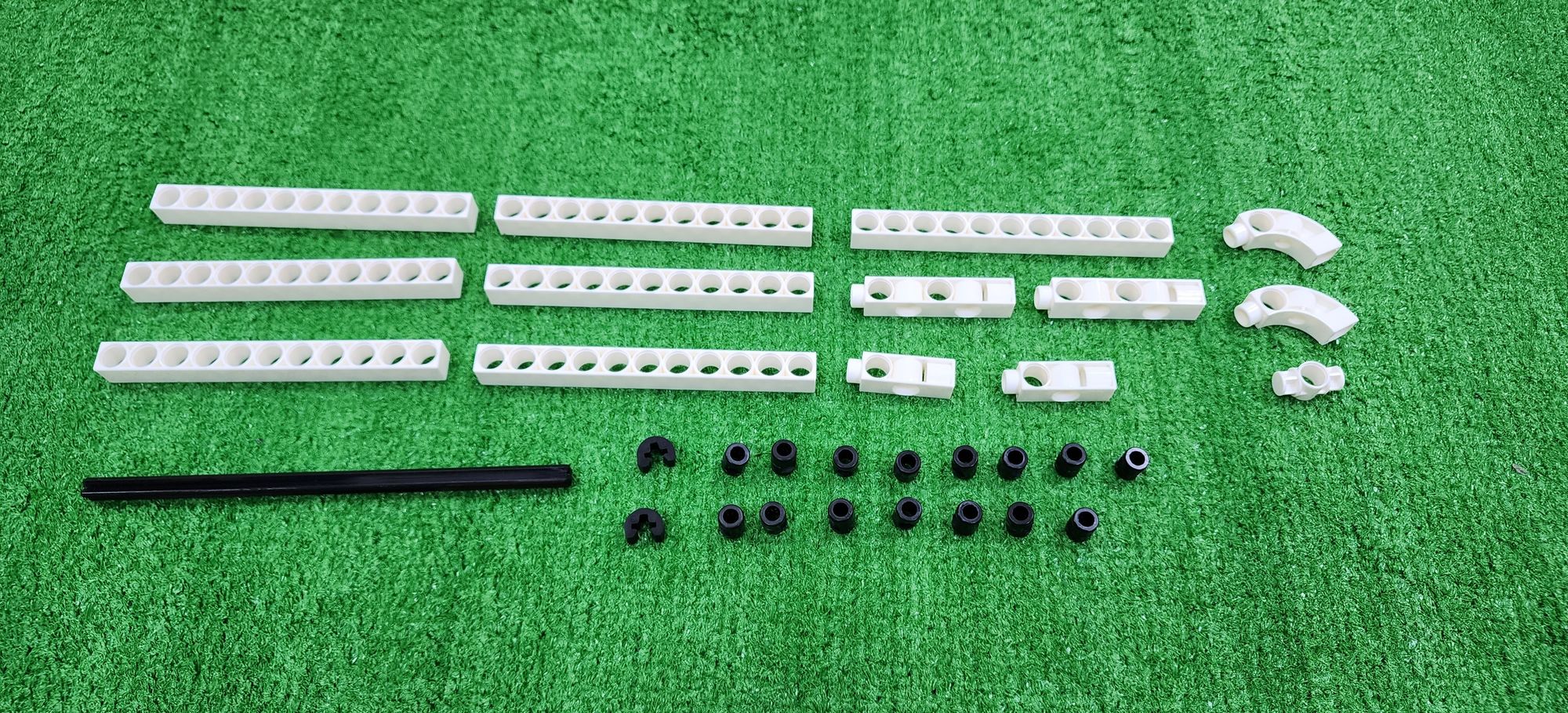
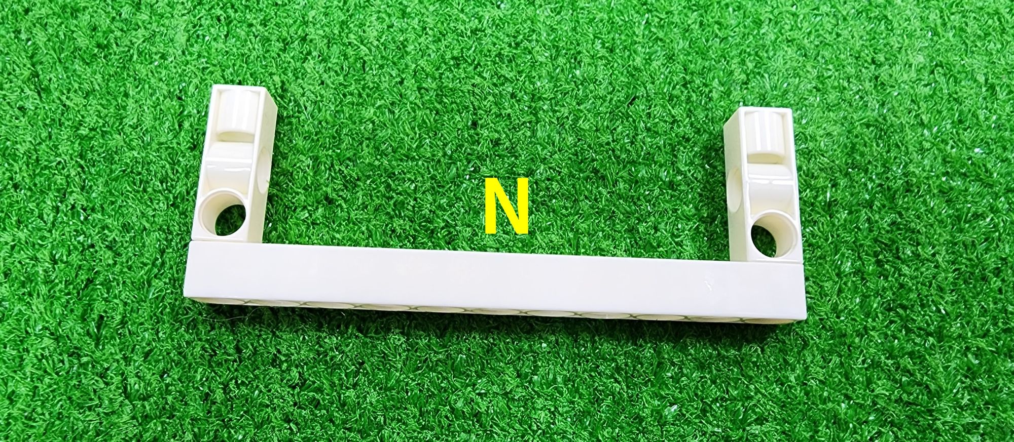
Step 52: We need to use the C-11 HOLE ROD and the C-3 HOLE DUAL ROD. And then combine them to complete the production of part N (Figure 145).
Step 53: We need to use the C-11 HOLE ROD and the B-SHORT PEG. Combine them to complete the production of two part O (Figure 146).
Step 54: We need to use the C-5 HOLE DUAL ROD, C-1 HOLE CONNECTOR, and the B-SHORT PEG. Combine them to complete the production of two part P (Figure 147).
Step 55: We need to combine two part O and one part P and define this newly completed part as part Q (Figure 148).
Step 56: We need to use part N, part Q, and the B-SHORT PEG. Combine them to complete the production of part R (Figure 149).
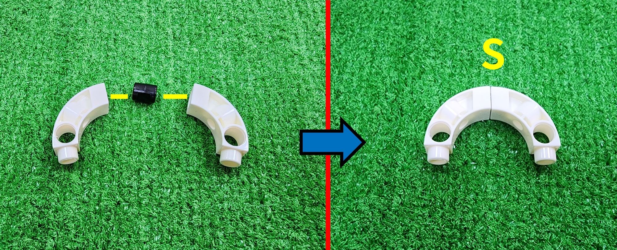
Step 57: We need to use the C-BENDED ROD and the B-SHORT PEG. Combine them to complete the production of part S (Figure 150). Then, install part S onto the previously completed part R (Figure 151).
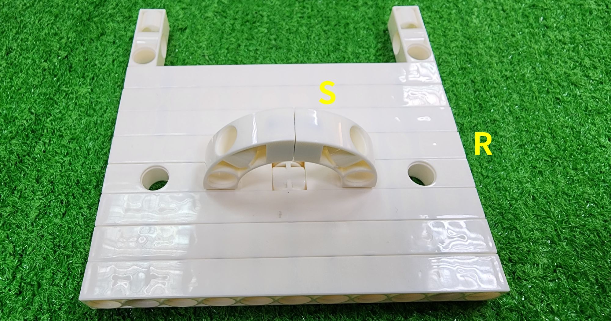
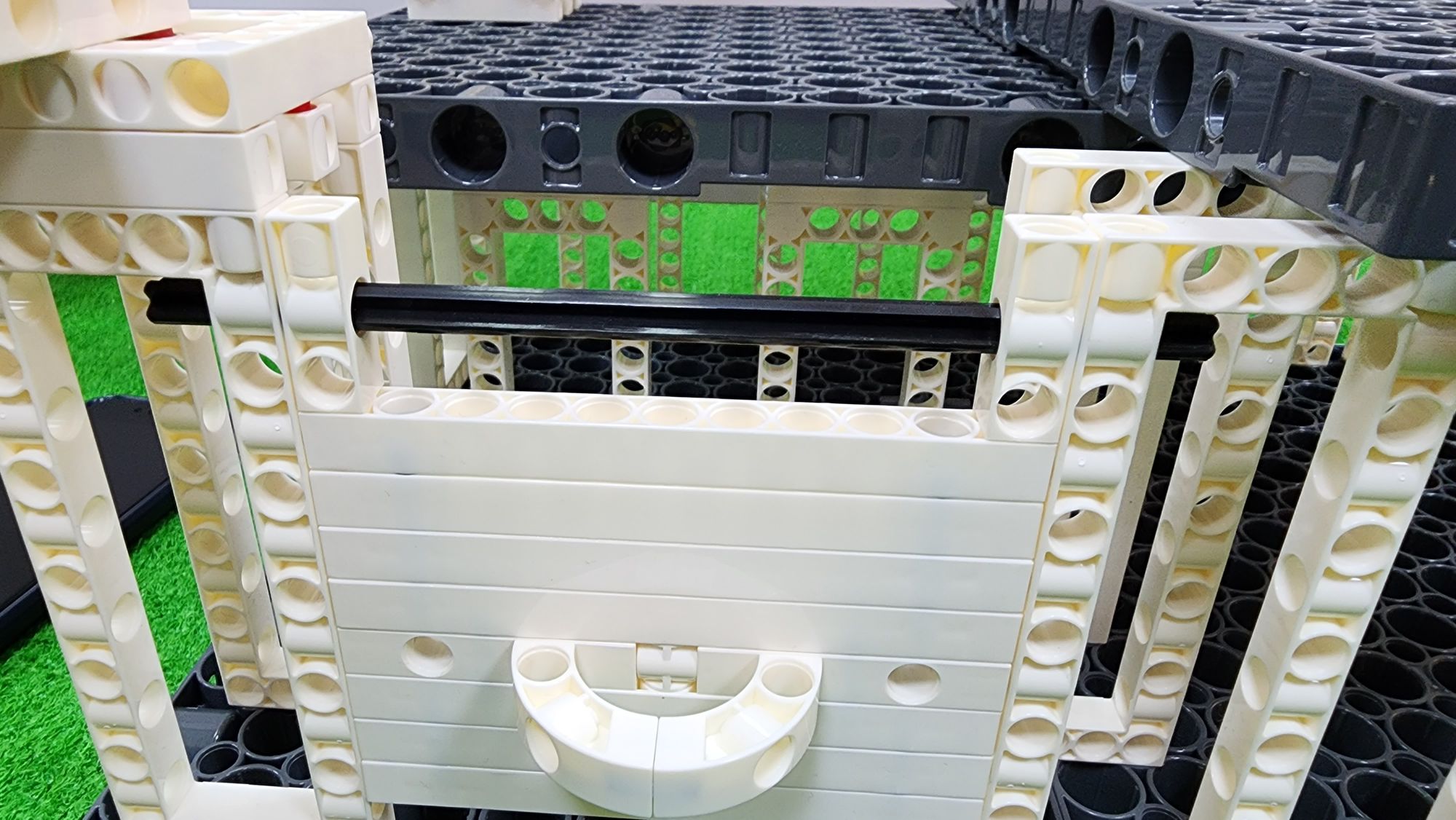
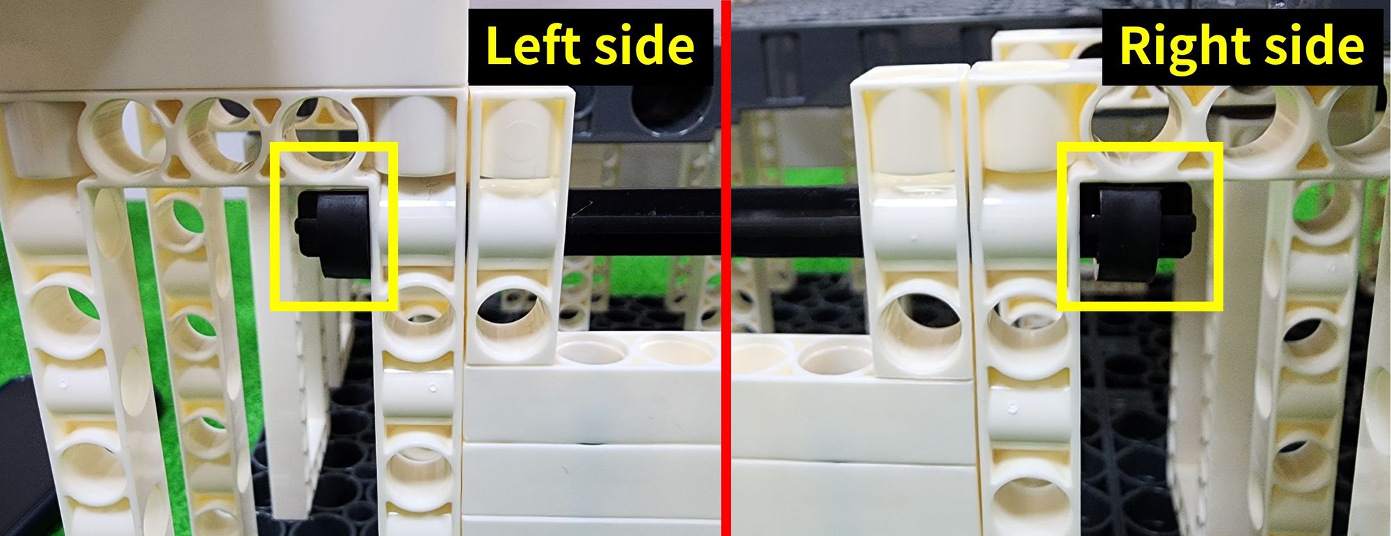
Step 58: We need to use the C-150mm AXLE Ⅰ and the C-AXLE FIXING. To combine the prize gate with the claw machine, first, place part R between the two C-5×13 DUAL FRAME as shown. Then, thread the C-150mm AXLE Ⅰ through the prize gate and the two C-5×13 DUAL FRAME (Figure 152). Finally, install the C-AXLE FIXING on both sides of the C-150mm AXLE Ⅰ(Figure 153). This completes the production of the prize gate.
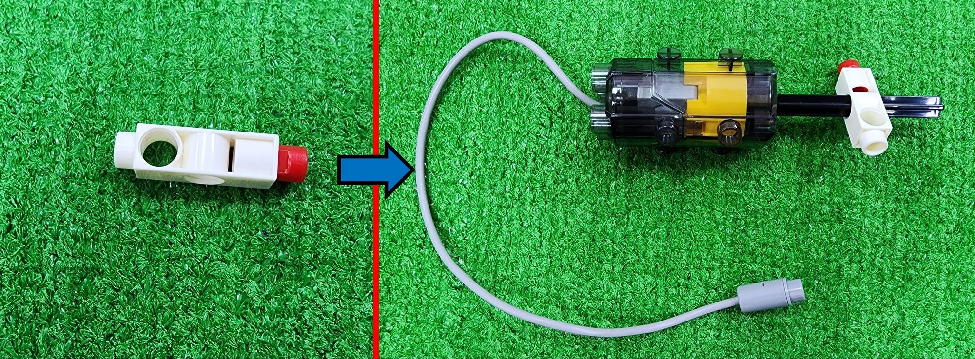
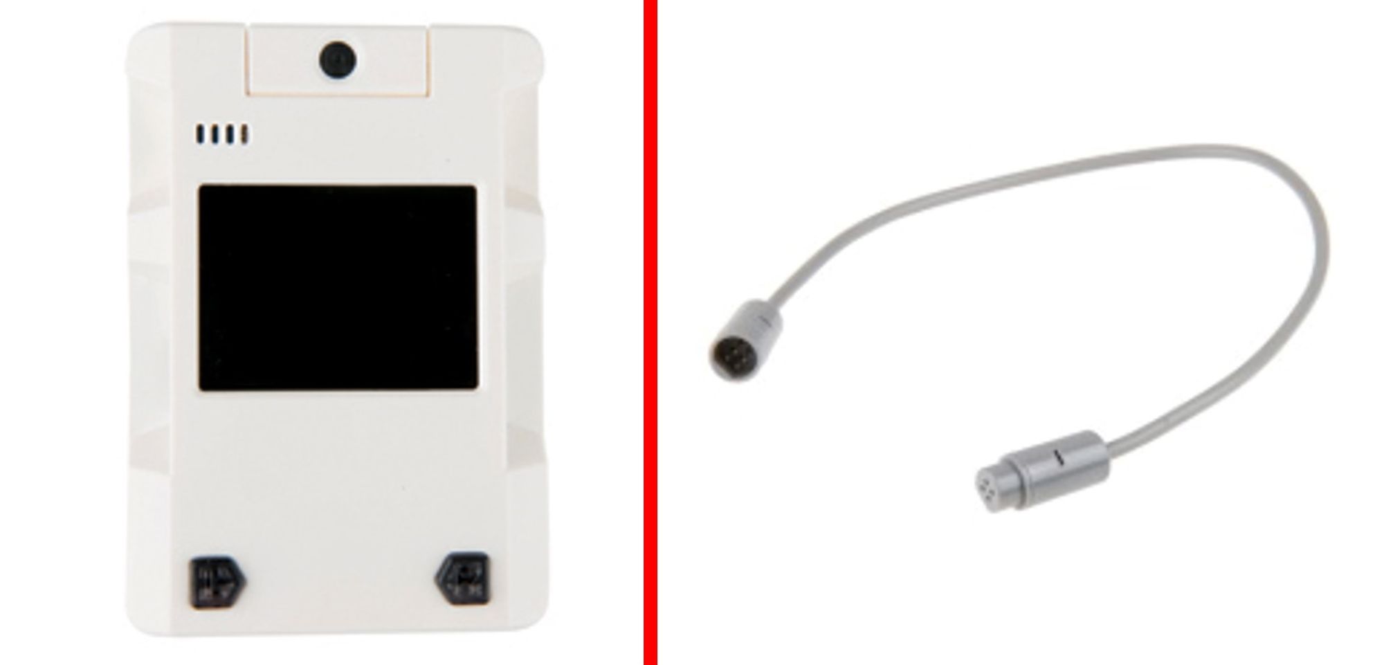
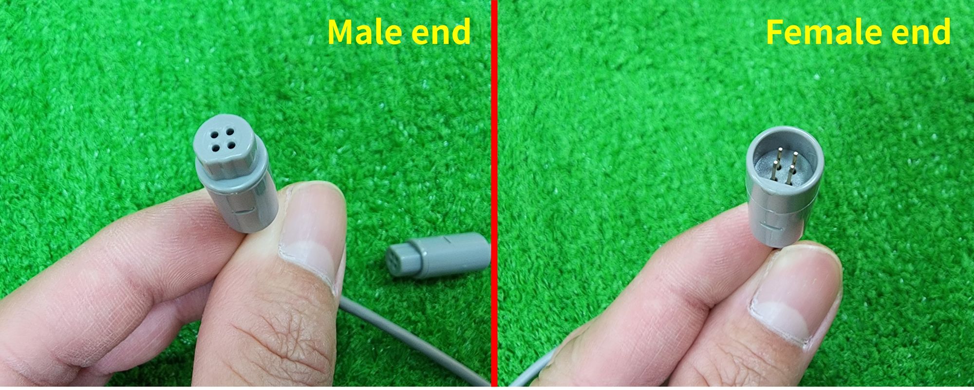
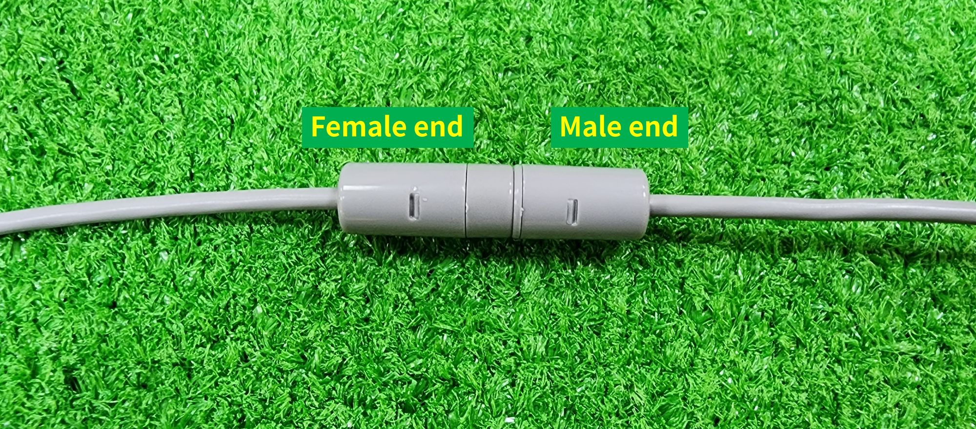
Now we are going to proceed with the wiring of the claw machine, requiring the use of C-EXTENSION CORD (1246-W85-D) and the Gigo #1206 set's C-Gigo AI CONTROL BOX (1206-W85-A) (Figure 154). Before wiring, Teacher Raccoon will first teach everyone how to distinguish between the male and female ends of the C-EXTENSION CORD (Figure 155). The male end usually has a protrusion, while the female end has a recess. When installing C-EXTENSION CORD, we will connect their male and female ends to extend the electrical wiring (Figure 156). Now let's proceed with the installation of the C-EXTENSION CORD.
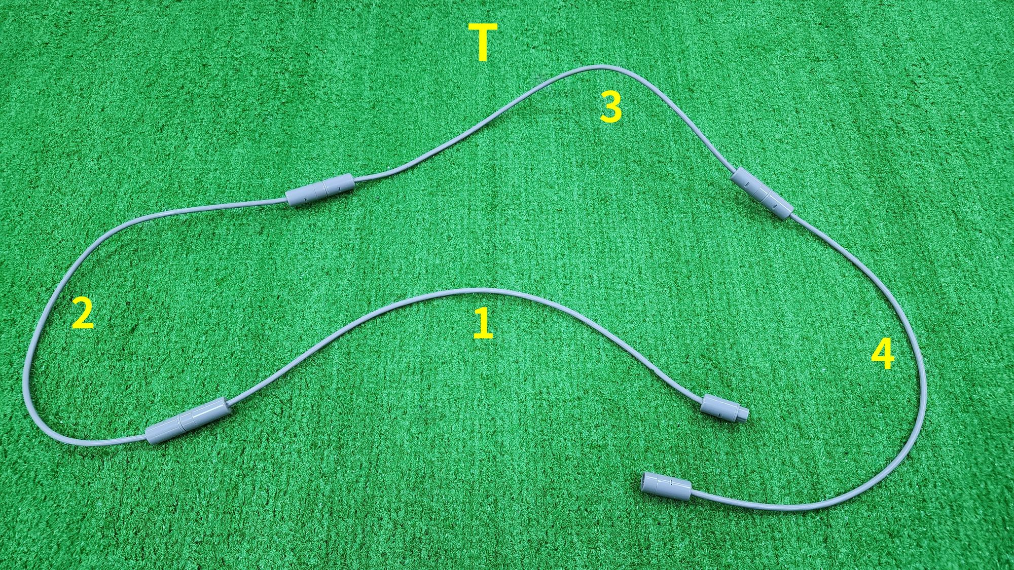
Step 59: We need to connect the male and female ends of the four C-EXTENSION CORD, and this combination is called as part T (Figure 157).
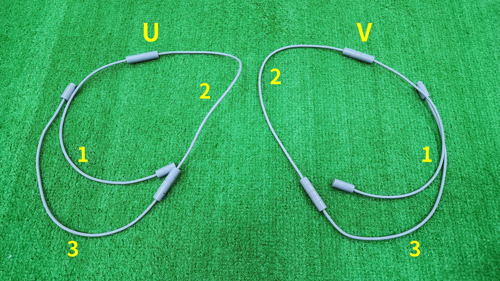
Step 60: The male and female ends of the three C-EXTENSION CORD need to be connected. Two sets need to be made in total. We will respectively refer to the combination of these three C-EXTENSION CORD as part U and part V (Figure 158).
Step 61: We are going to wire the front and rear carriages. First, connect the male end of part T to pin A of the C-Gigo AI CONTROL BOX. Then, connect the female end of part T to the male end of the C-50X PLANETARY GEARBOX in part G (Figure 159).

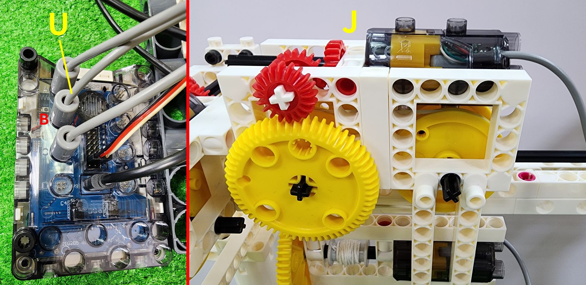
Step 62: We are going to wire the left and right carriages (part J). First, connect the male end of part U to pin B of the C-Gigo AI CONTROL BOX. Then, connect the female end of part U to the male end of the C-50X PLANETARY GEARBOX in part J (Figure 160).
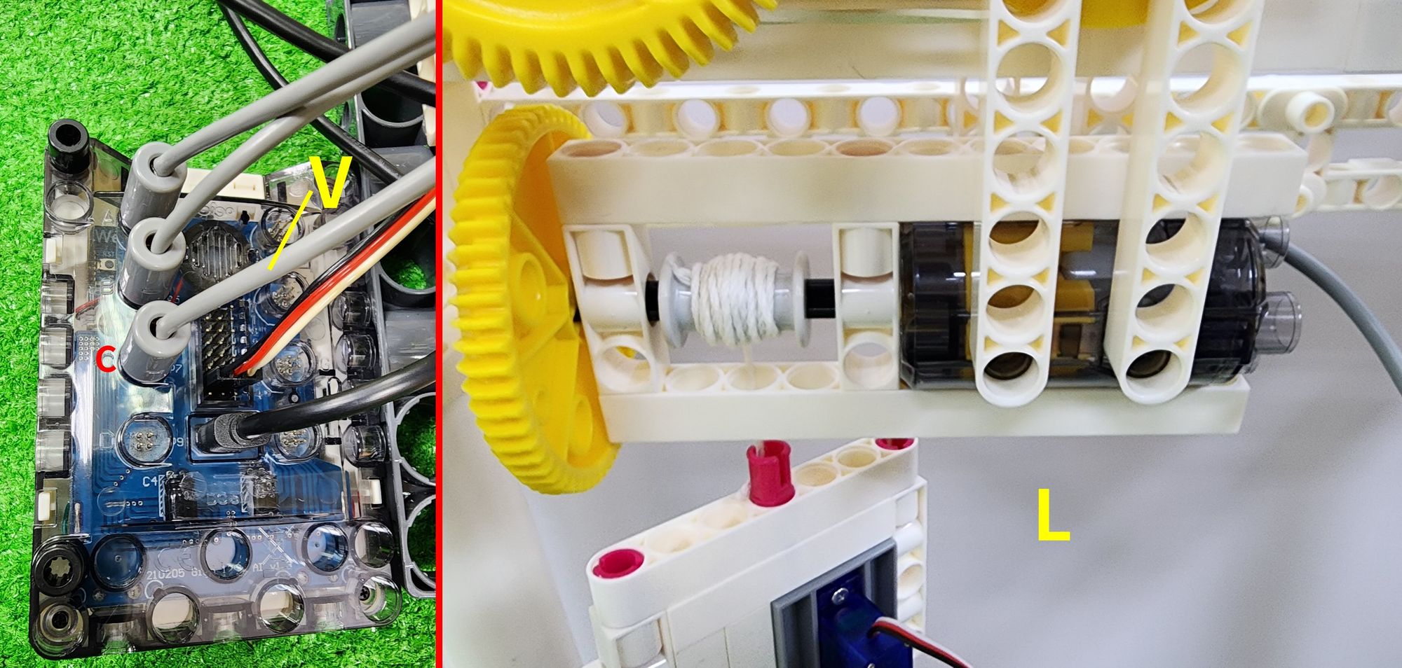
Step 63: We are going to wire the coiling device (part L). First, connect the male end of part V to pin C of the C-Gigo AI CONTROL BOX. Then, connect the female end of part V to the male end of the C-50X PLANETARY GEARBOX in part L (Figure 161).
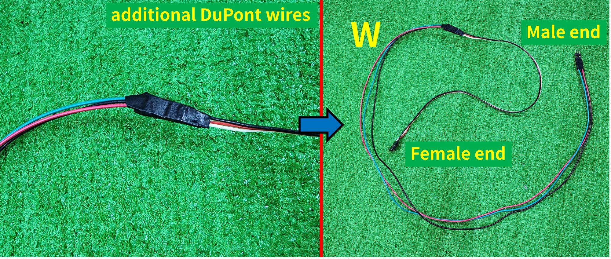
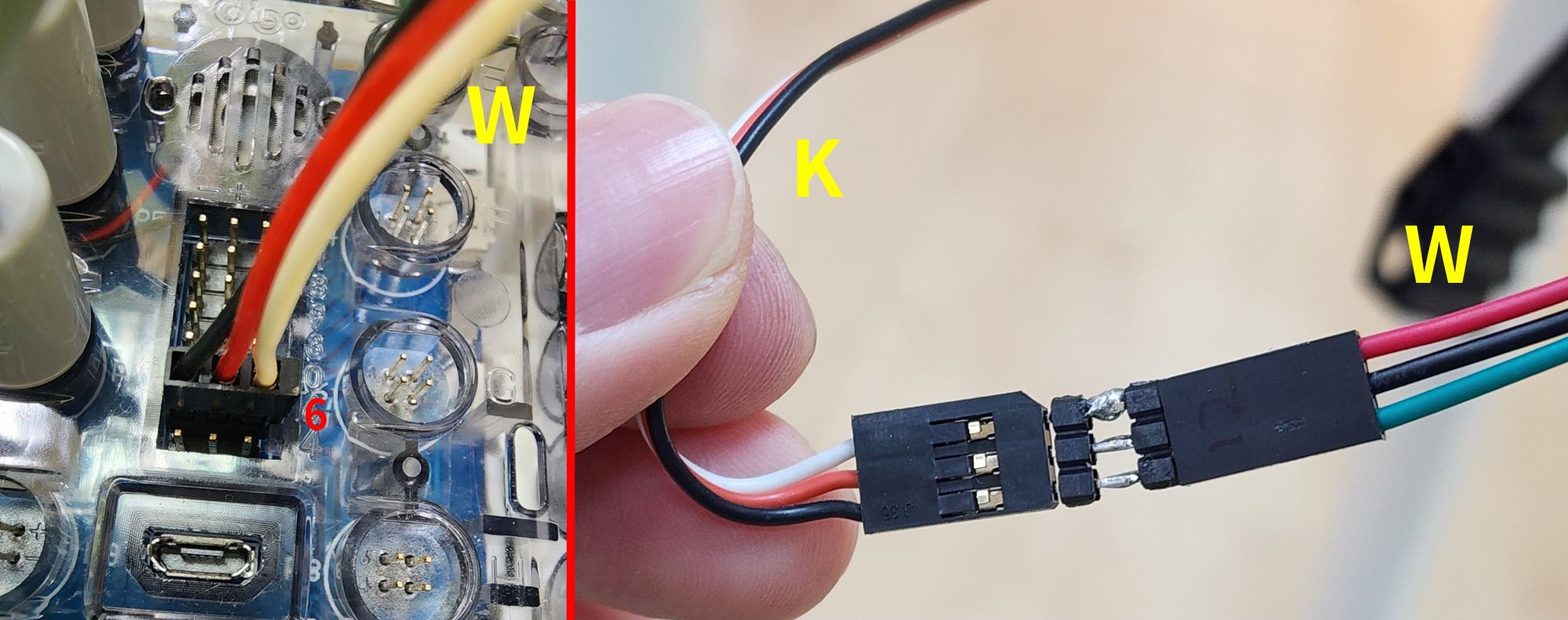
Before wiring the claw (part K), Teacher Raccoon would like to remind everyone that because the C-180° SERVO MOTOR used for the claw requires DuPont wires, we will need to buy additional DuPont wires of sufficient length or connect existing DuPont wires together to proceed with the wiring. We will define this connected DuPont wire as part W (Figure 162).
Step 64: To wire the claw (component K), first connect the female end of part W to pin 6 of the C-Gigo AI CONTROL BOX. Then, connect the male end of part W to the female end of the C-180° SERVO MOTOR in part K (Figure 163).
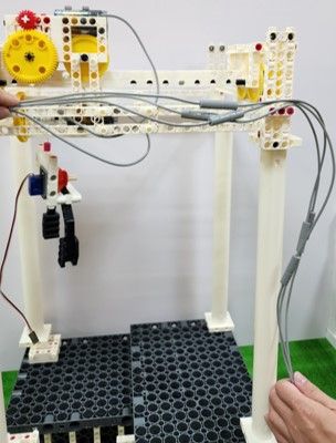
Now all the wiring is completed (Figure 164). We can use cable ties to bundle the wires together for neatness, or pass the wires through the E-410mm TUBE to keep them tidy and clean.
If you don't have cable ties on hand, you can also use Gigo's newly developed C-CABLE FIXER (1409-W10-F1S) (Figure 165). This component allows you to gather and secure wires onto Gigo blocks.
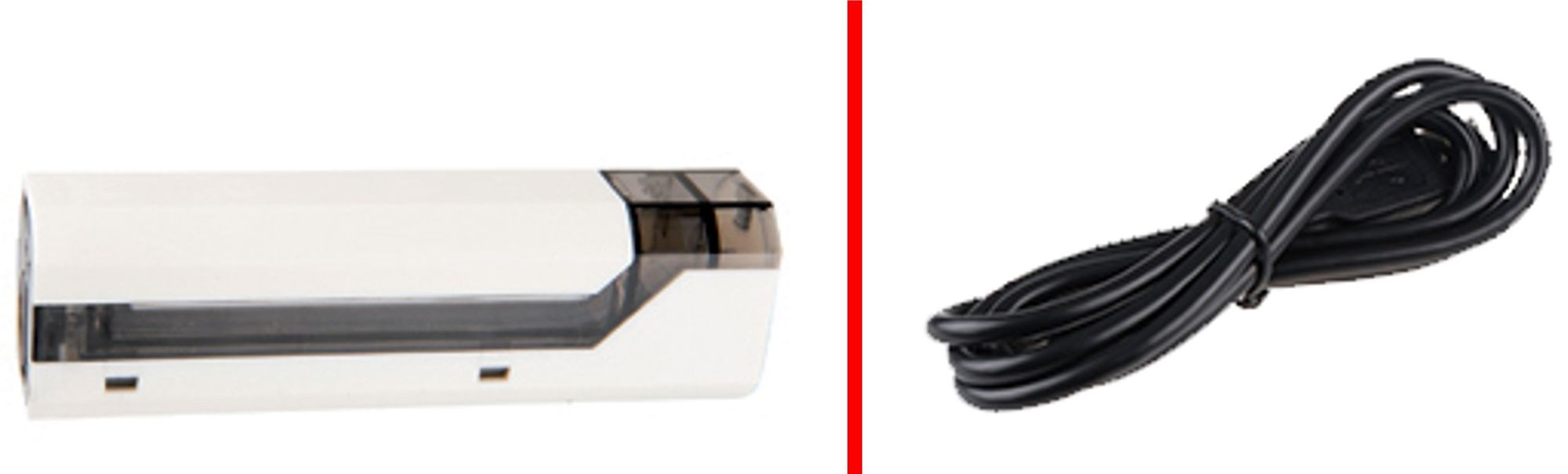
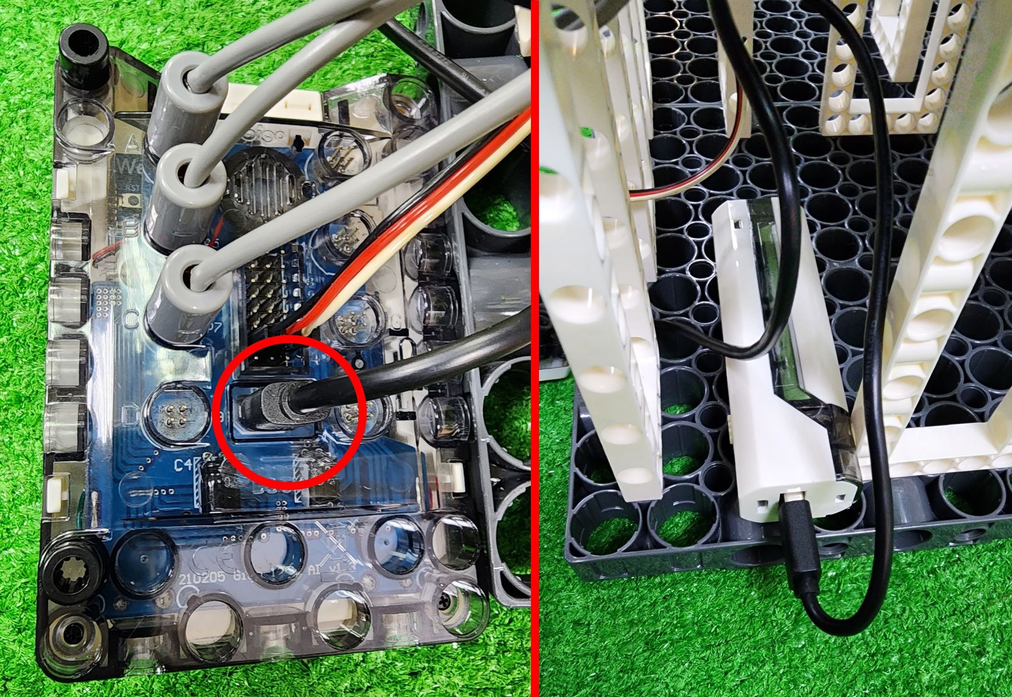
Step 65: We're going to configure the power supply for the claw machine. We'll need to use the C-Gigo LITHIUM BATTERY HOLDER (1206-W85-B) and the C-MicroUSB 2.0 CABLE (E30#1247A) (Figure 166). First, use the C-MicroUSB 2.0 CABLE to connect the C-Gigo AI CONTROL BOX to the C-Gigo LITHIUM BATTERY HOLDER with the 18650 batteries inserted. Then, securely fasten the C-Gigo LITHIUM BATTERY HOLDER to the claw machine to complete the power configuration (Figure 167).
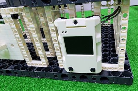
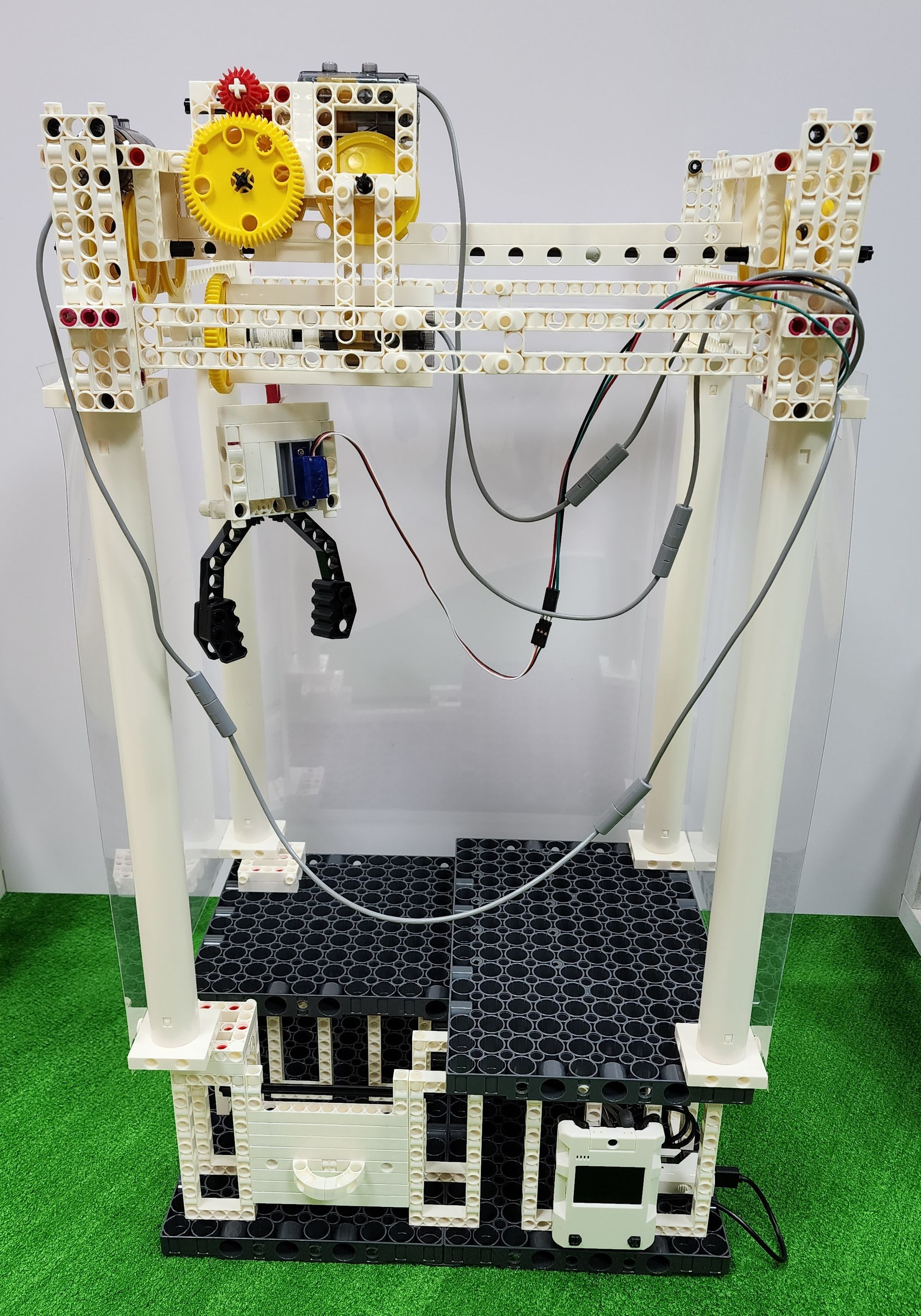
Finally, use B-SHORT PEG to secure the C-Gigo AI CONTROL BOX to the claw machine (Figure 168). With that, we've completed an awesome claw machine!٩(๑>∀<๑)۶ You can also use C-SHORT BUTTON FIXER to secure transparent plastic sheets to the frame of the claw machine, simulating the effect of a glass partition (Figure 169).
◆ Write a program
Although we've completed the construction of the claw machine, it won't function without programming. Now, let's follow Teacher Raccoon's lead and complete the programming for the claw machine.
Step 1: We first turn on the computers and access the Web: AI Programming Block Platform. Through this platform, we can write programs and use Wi-Fi to burn the program into the C-Gigo AI CONTROL BOX. For more information about the C-Gigo AI CONTROL BOX and the #1206 AI EDUCATIONAL BLOCKS, you can refer to Teacher Sloth 's [Education Time Machine EP9].
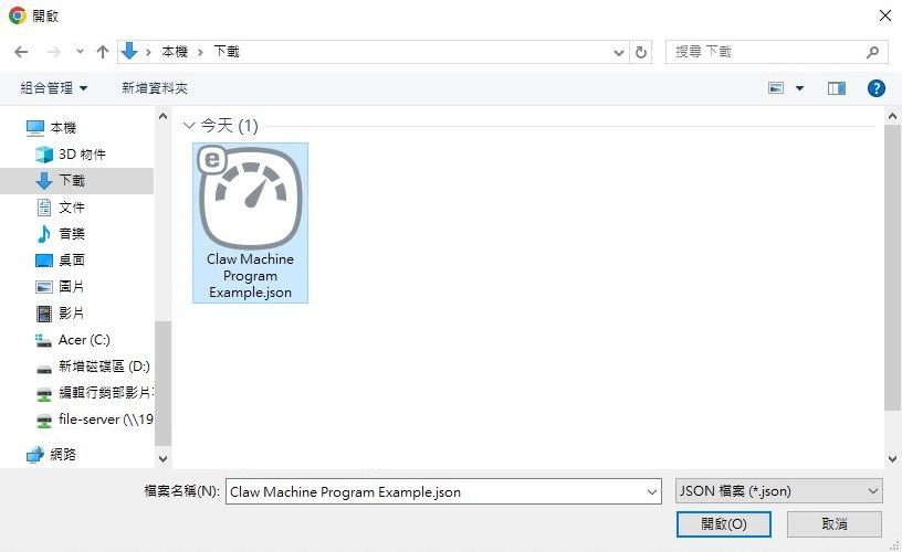
Step 2: We now access the following google drive folder and download the file named "Claw Machine Program Example" (Figure 170). Download the program for the claw machine to your computer.


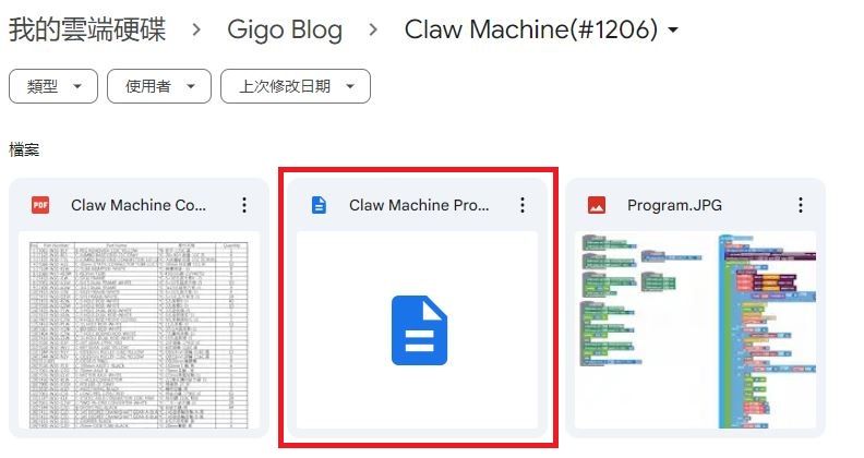
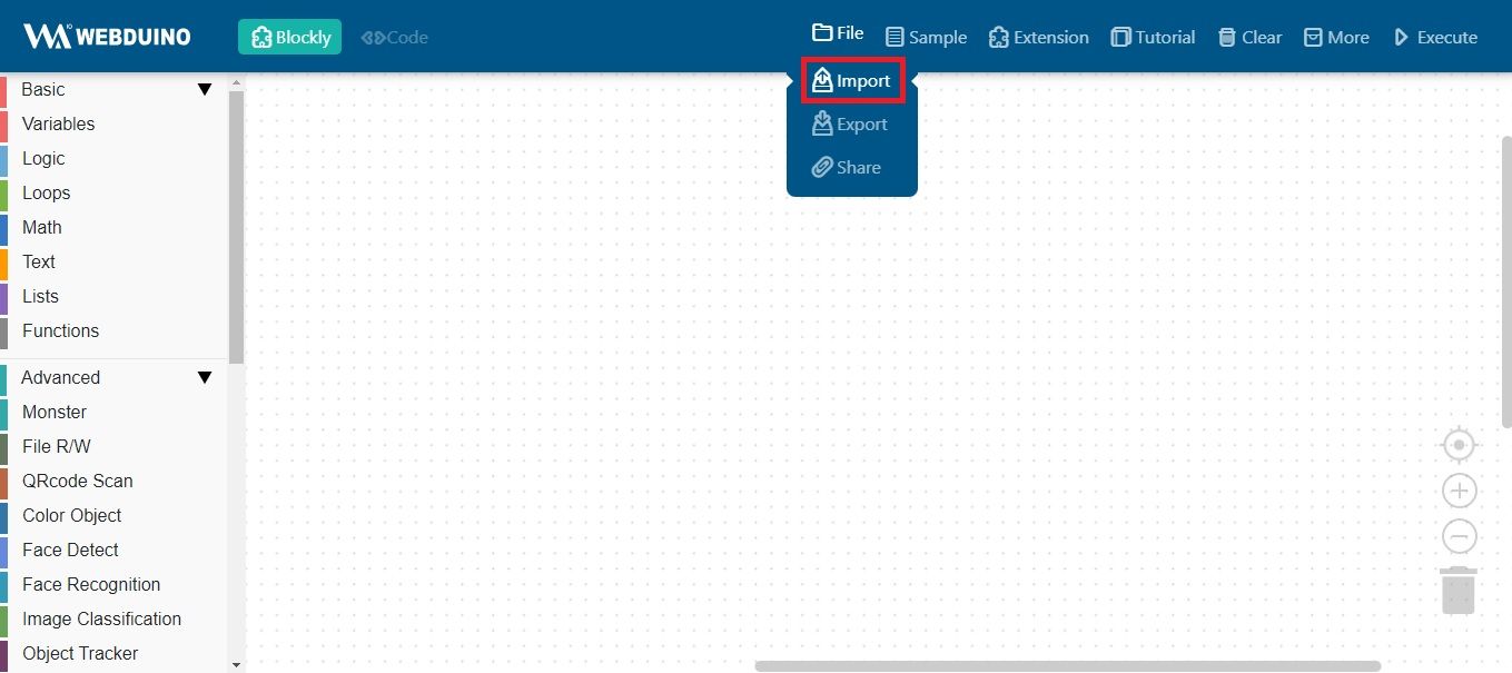
Step 3: We're going to open the program for the claw machine through the Web: AI Programming Block Platform. First, click on "File" in the top right corner ⮕ "Import" (Figure 170), and then click on the claw machine program example in the folder (Figure 171).
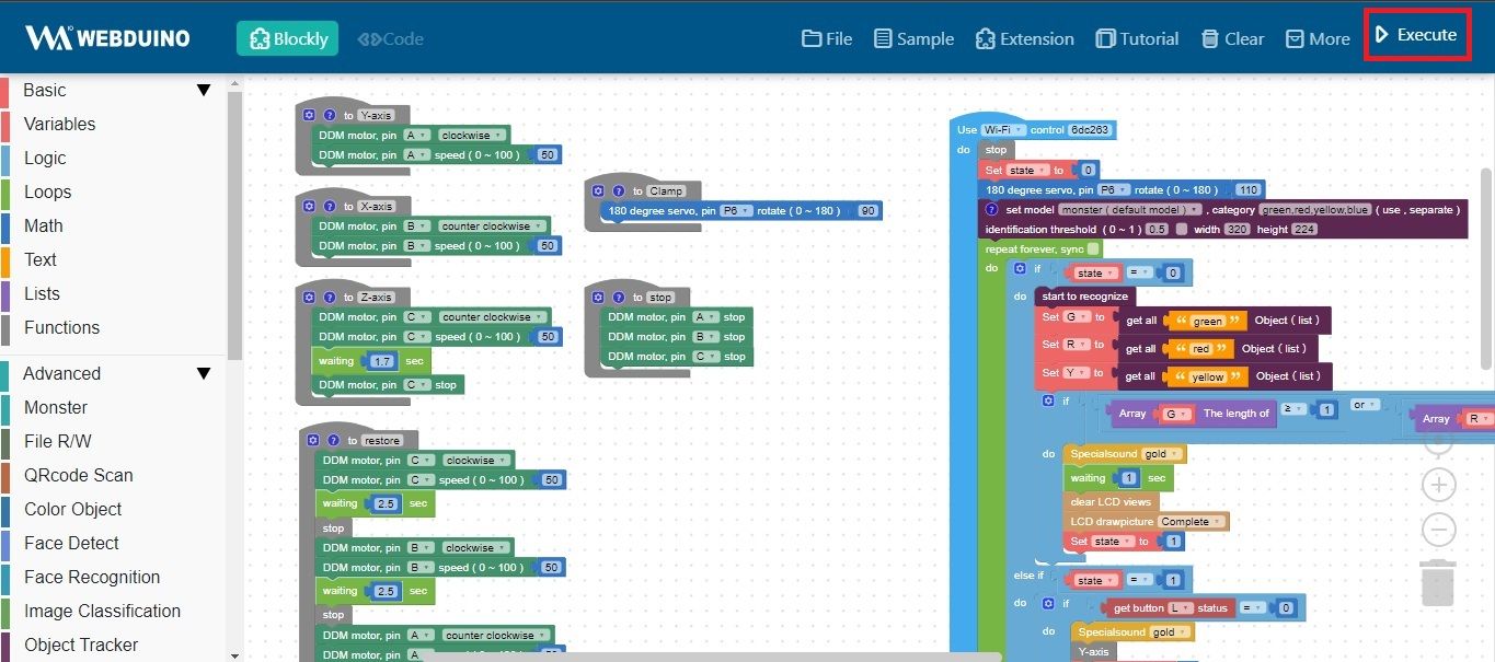
Now we have successfully opened the program for the claw machine (Figure 173). Since this program is quite complex, Teacher Raccoon won't explain each part of the program. Instead, we will provide a brief introduction to the functions, which are highlighted in red boxes.
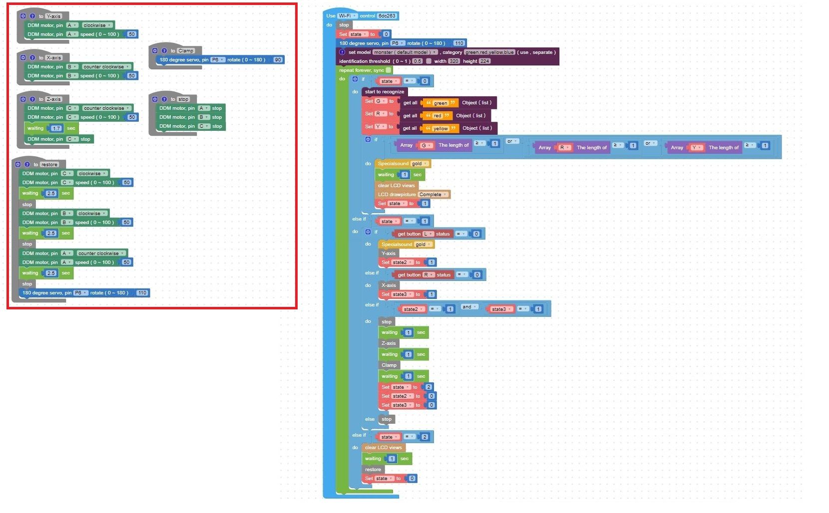
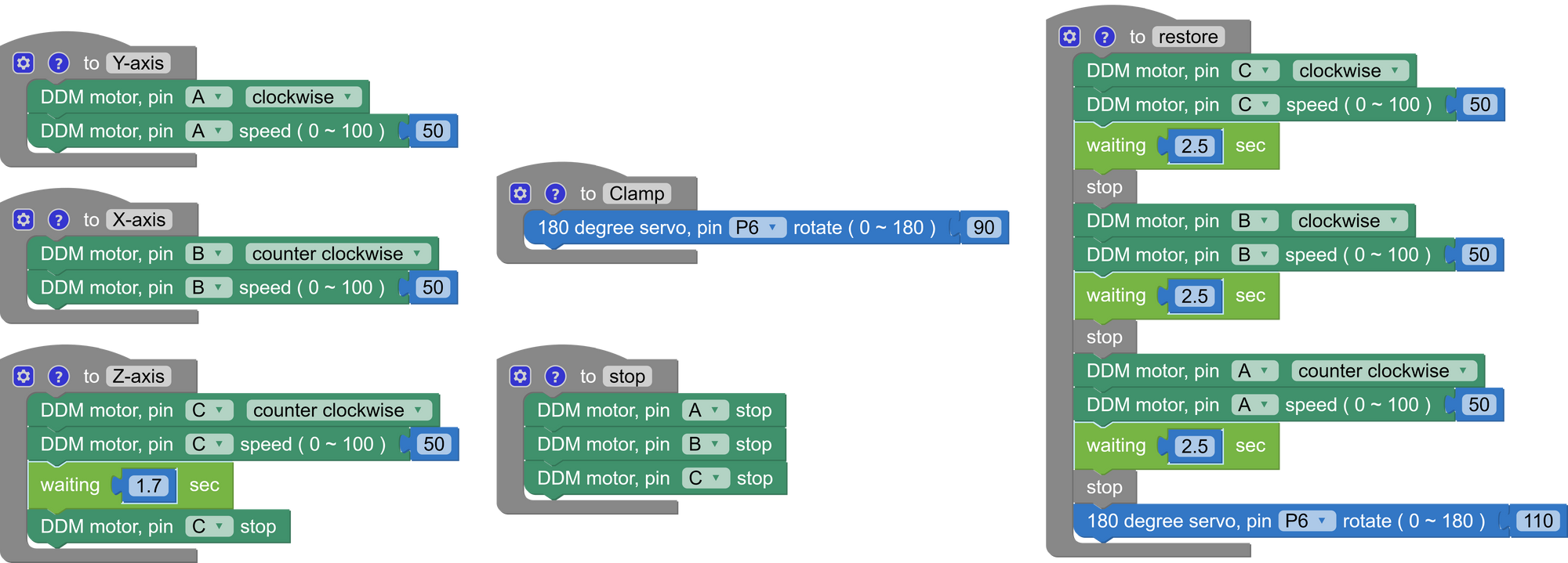
The functions of the claw machine can be divided into six types (Figure 174), namely:
1. Y-axis: Controls the front and rear carriage, corresponding to the front and back position of the claw.
2. X-axis: Controls the left and right carriage, corresponding to the left and right position of the claw.
3. Z-axis: Controls the coiling device, corresponding to the vertical position of the claw.
4. Clamp: Controls the claw of the claw machine.
5. Stop: Halts the movement of the front and rear carriage, left and right carriage, and coiling device.
6. Restore: Moves the claw back to its original position.
You can increase the motor speed in the Y-axis and X-axis functions to accelerate the movement of the front and rear carriage as well as the left and right carriage, allowing the claw to move more quickly. Alternatively, you can adjust the angle of the C-180° SERVO MOTOR in the Clamp function to ensure a firmer grip when the claw grabs objects.
Once we've finished programming, we can click on "Execute" in the top right corner (Figure 175). This will allow us to burn the program for the claw machine into the C-Gigo AI CONTROL BOX via Wi-Fi. After completion, we can get ready to operate the claw machine!
◆ How to Play
First, we need to power on the C-Gigo LITHIUM BATTERY HOLDER and ensure that the C-Gigo AI CONTROL BOX successfully connects to the Wi-Fi network at the location before we can operate the claw machine. Through video 1, we observe the following sequence of actions:
1. When the camera of the control box detects the green monster, a green check mark is displayed (0:00~0:08).
2. At this point, we can use the L key to control the forward and backward movement of the claw by the front and rear carriages, and then use the R key to control the left and right movement of the claw by the left and right carriages (0:08~0:13).
3. Once the position adjustment is completed, the coiling device will start operating, lowering the claw. After the claw grasps the item, it will be lifted (0:13~0:21).
4. Subsequently, the left and right carriages and the front and rear carriages will return the claw to its original position, and finally, the claw will be opened to release the item (0:21~0:26).
◆Conclusion
The claw machine model we've built this time is more complex than previous ones. Teacher Raccoon suggests that adults assist during assembly, especially with the assembly of the various carriages and tracks. If one part is assembled incorrectly, the claw machine may not work.
Additionally, you can try competing with friends to see who can grab the most items with the claw machine. Let's become claw machine masters!
◆Scientific Principle
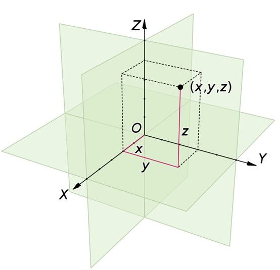
In the claw machine model, we use the left and right carriages, front and rear carriages, and coiling device to control the position of the claw (Video 2). This application corresponds to the Cartesian coordinate system (Figure 176). The Cartesian coordinate system divides space into three dimensions (3 Dimensions): the X-axis for left-right direction, the Y-axis for front-back direction, and the Z-axis for up-down direction. Regardless of the item's position, we can mark it using these three dimensions.
The coordinate system serves as a bridge between geometry and mathematics, widely applicable in geography, astronomy, and physics. Examples include latitude and longitude on maps, indicating the relative positions of celestial bodies and the Earth, and reference coordinate systems for objects moving in space.
◆Curriculum(NGSS)
3-PS2-1 Plan and conduct an investigation to provide evidence of the effects of balanced and unbalanced forces on the motion of an object.
3-5-ETS1-1 Define a simple design problem reflecting a need or a want that includes specified criteria for success and constraints on materials, time, or cost.
3-5-ETS1-2 Generate and compare multiple possible solutions to a problem based on how well each is likely to meet the criteria and constraints of the problem.
◆Reference

 飛騰
飛騰
Please sign in to vote.