Science in daily life: EP15 – hidden Blade

Hello, everyone! I’m Teacher Raccoon. Do you enjoy playing computer games? Speaking of games, I’d like to introduce you to an action-adventure series that blends historical knowledge with immersive gameplay—Assassin’s Creed.
The Assassin’s Creed series is renowned for its meticulous recreation of historical periods. Each installment takes place in a different era, such as the Levant during the Third Crusadein the first game or Renaissance Italy in the second. The cities, architecture, and characters are all designed with historical accuracy, allowing players to fully experience the atmosphere of the past. In the game, you take on the role of an assassin, interact with historical figures, and engage in thrilling parkour and missions.

One of the most iconic elements of the series is today’s theme—the hidden blade. This fictional weapon is inspired by real-world hidden weapons and consists of a wristband and a retractable blade. Normally concealed within the wristband, the blade extends through a mechanism triggered by the wearer’s finger, allowing for swift and stealthy assassinations before retracting back into place.

Now, let Teacher Raccoon guide you step by step in building a hidden blade using building blocks!
◆ Assembly Steps
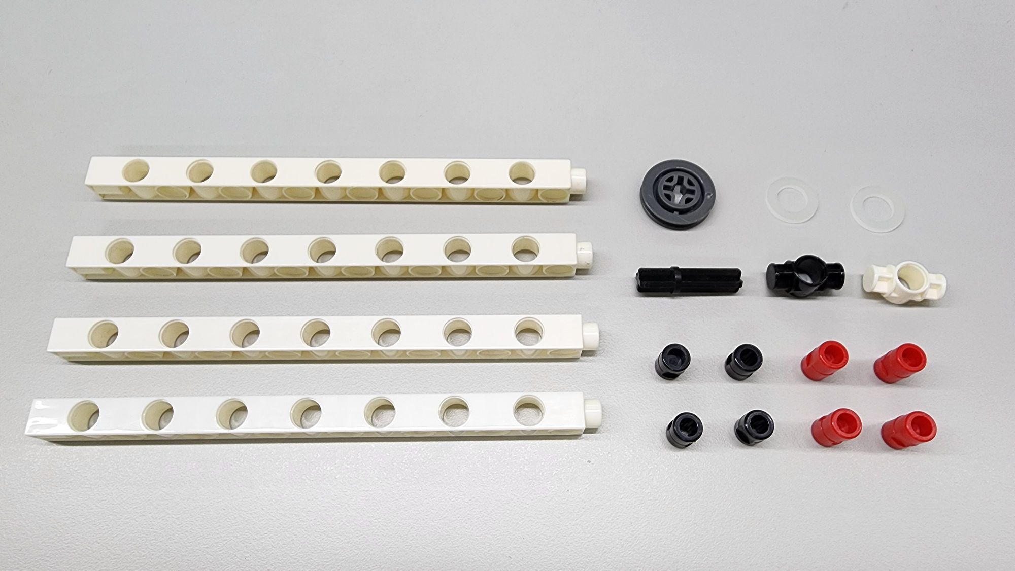
To start, assemble the lower base of the hidden blade using the following components:
- C-15 HOLE DUAL ROD
- C-OD23mm PULLEY
- C-30mm AXLE Ⅲ
- C-WASHER (M8×16)
- C-1 HOLE CONNECTOR
- B-SHORT PEG
- C-LONG PEG (Figure 1)
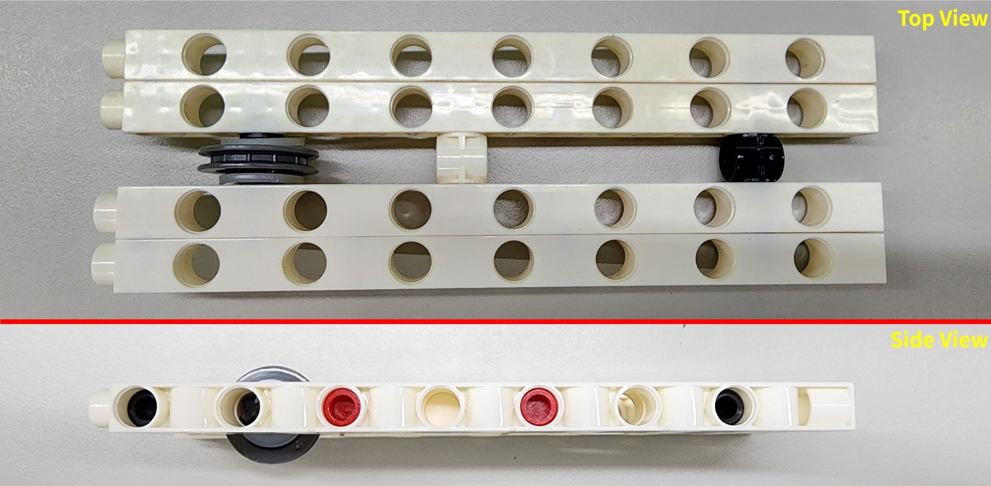
Follow the diagram to assemble the parts, ensuring that the long and B-SHORT PEGs and the C-WASHER (M8×16)are correctly positioned (Figure 2).
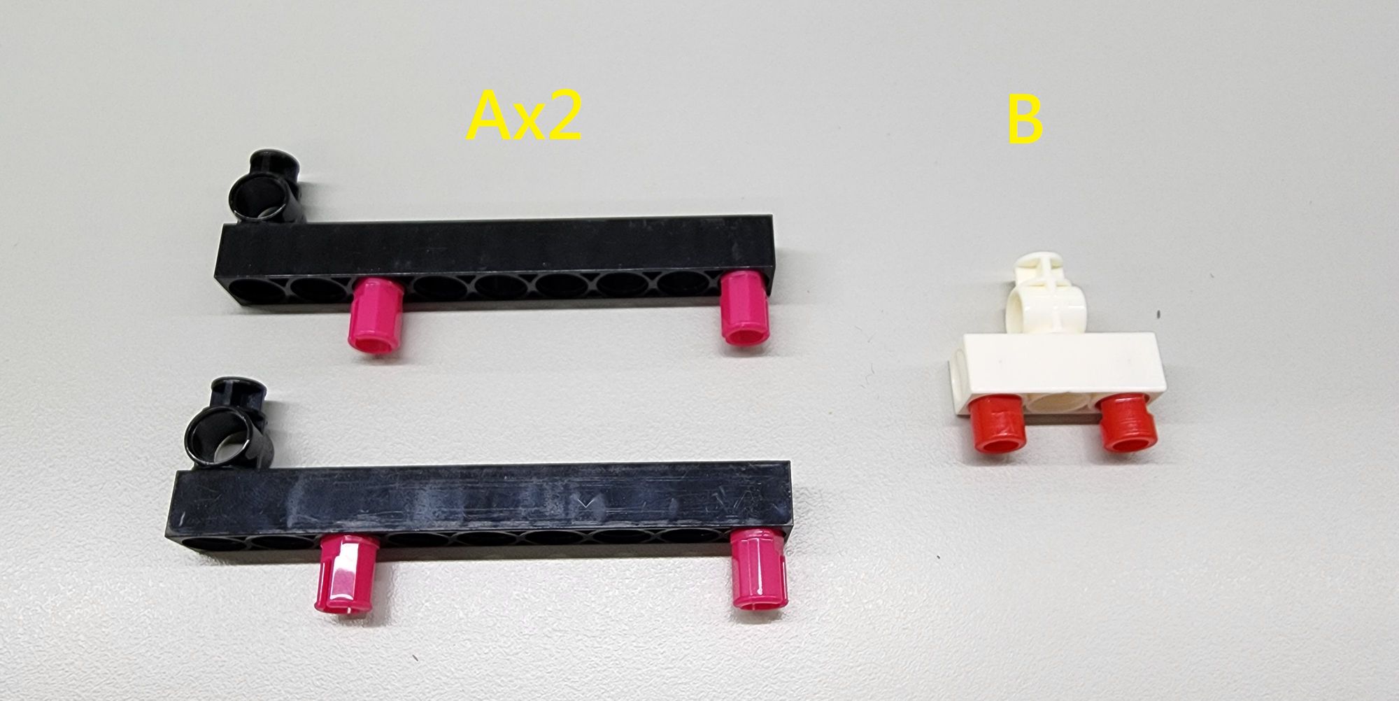
Step 2: Installing the Slide Rail
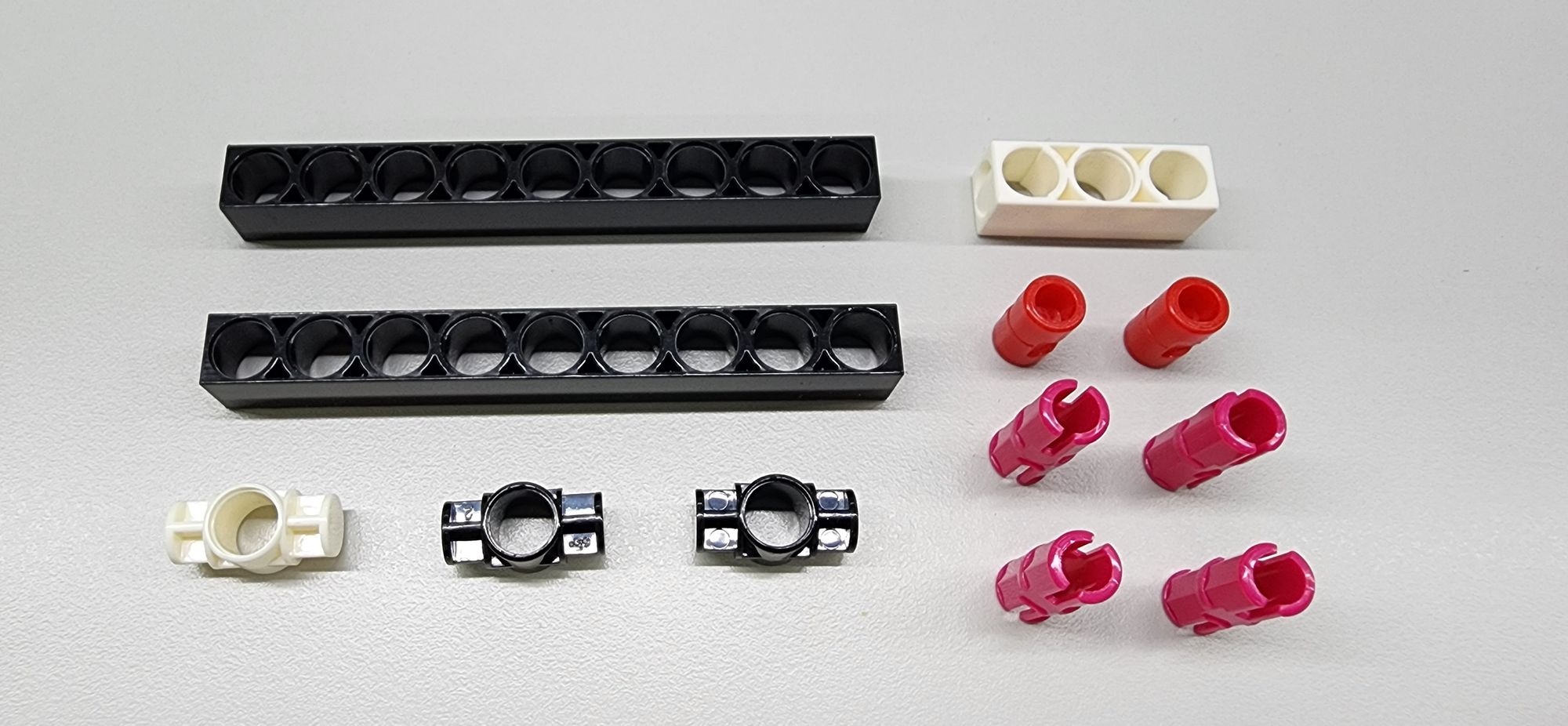
Next, install the slide rail on top of the lower base to allow the blade to move freely. You’ll need the following components:
- C-9 HOLE ROD
- C-3 HOLE ROD
- C-1 HOLE CONNECTOR
- C-LONG PEG
- C-STATIC AXLE CONNECTOR (Figure 3)
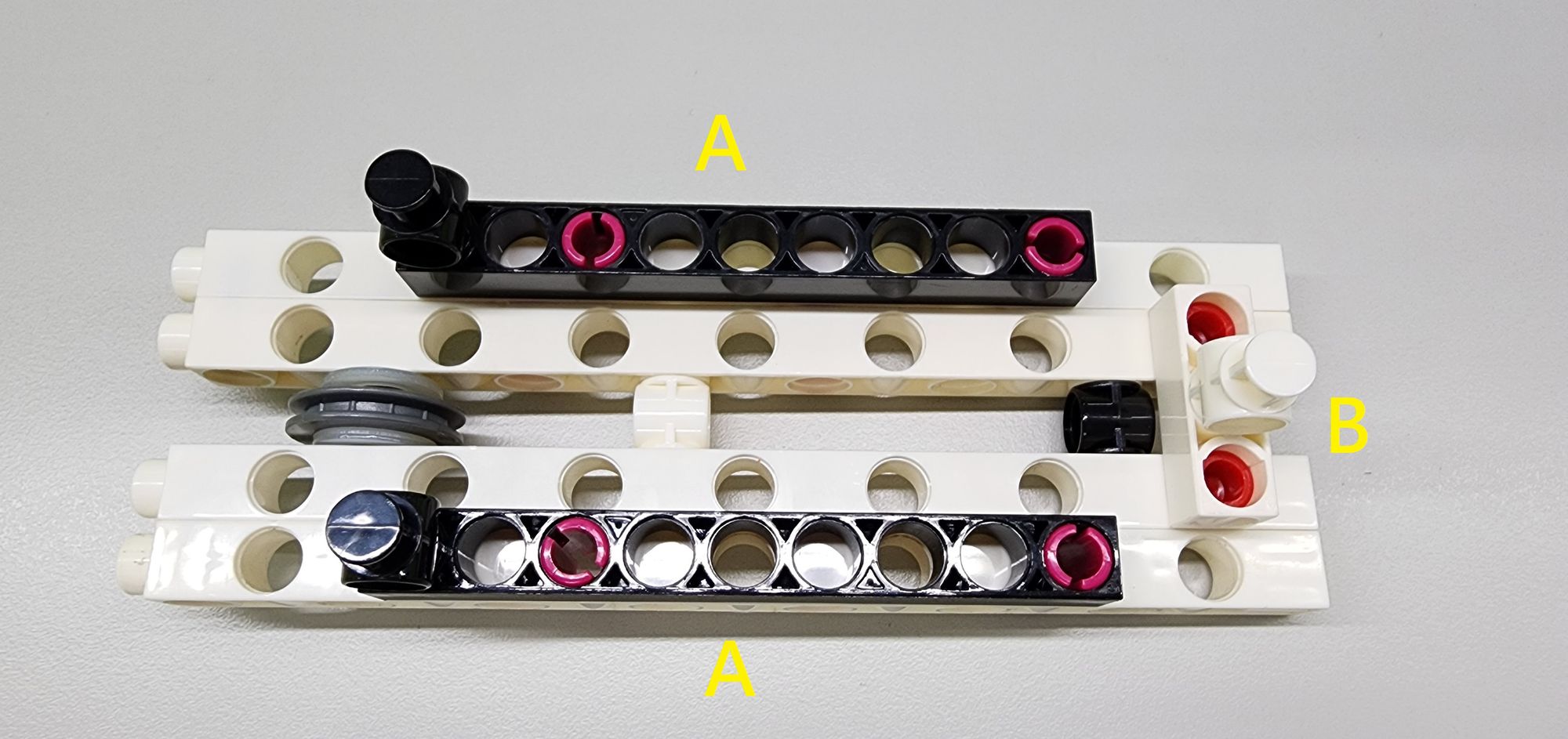
Assemble these parts accordingly to create two Part A components and one Part B component (Figure 4).
Next, attach Parts A and B to the lower base as shown. Part A helps stabilize the blade’s movement from left to right, while Part B secures the bottom of the blade (Figure 5).
Step 3: Assembling the Blade
To achieve the telescopic effect, the blade will be built in two layers: an inner blade and an outer blade.
First, let’s create the outer bladeusing the following components:
- C-3x13 DUAL FRAME
- Two C-1 HOLE CONNECTOR
- B-SHORT PEG (Figure 6)
Attach the Two C-1 HOLE CONNECTOR and B-SHORT PEG to the C-3x13 DUAL FRAME as shown to complete two Part C components (Figure 7).
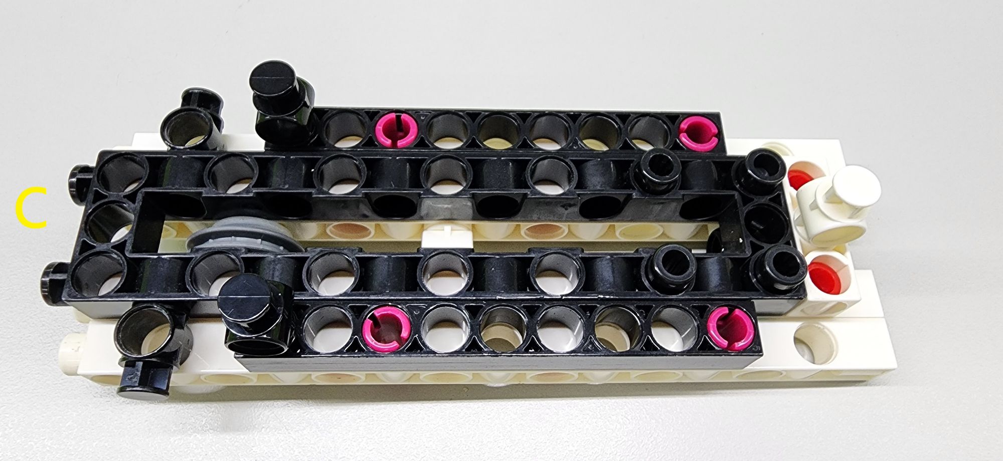
Next, position one Part C onto the lower base as shown (Figure 8). The other Part C will be used in later assembly steps, so set it aside for now.
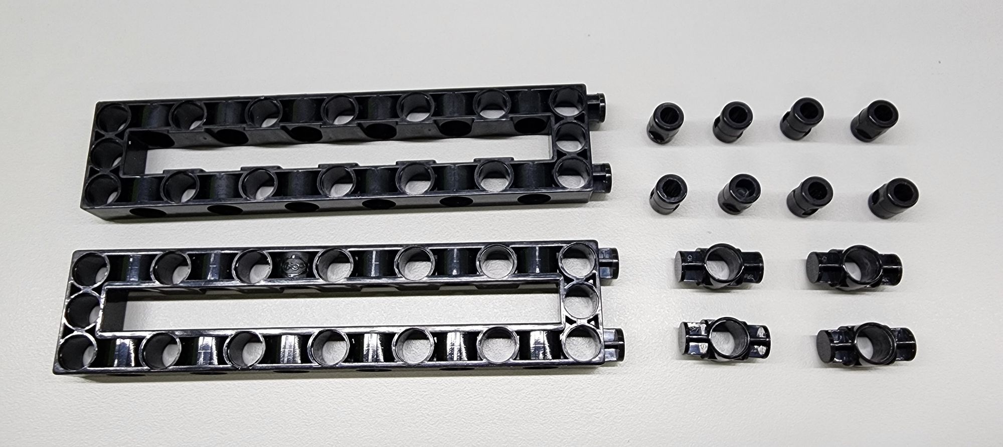
Step 4: Installing the Bracket
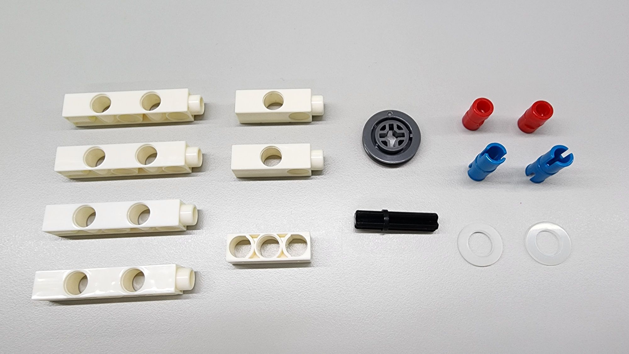
Next, install a bracket behind the blade to extend the outer blade and secure the movable pulley. You’ll need the following components:
- C-3 HOLE DUAL ROD
- C-5 HOLE DUAL ROD
- C-3 HOLE ROD
- C-OD23mm PULLEY
- C-30mm AXLE Ⅲ
- C-WASHER (M8×16)
- C-AXLE CONNECTOR
- C-LONG PEG (Figure 9)
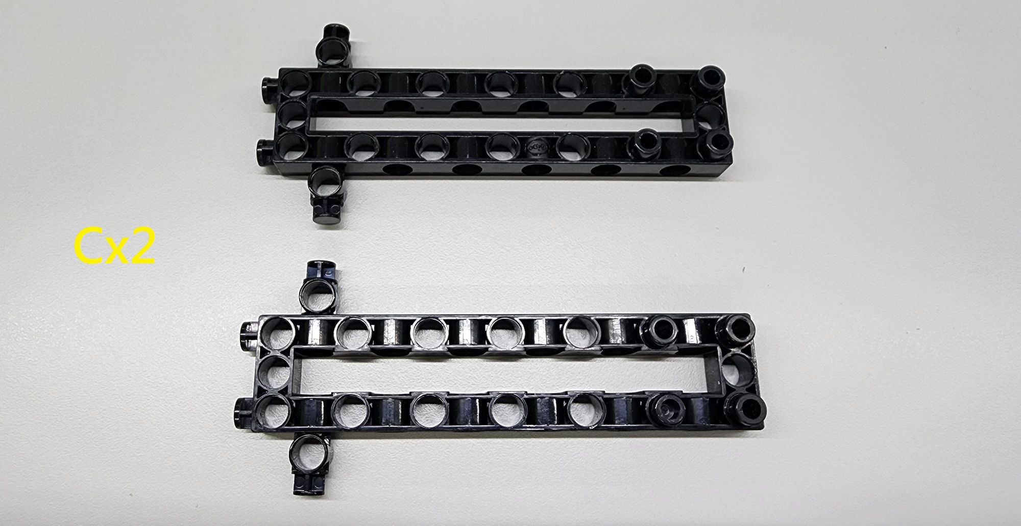
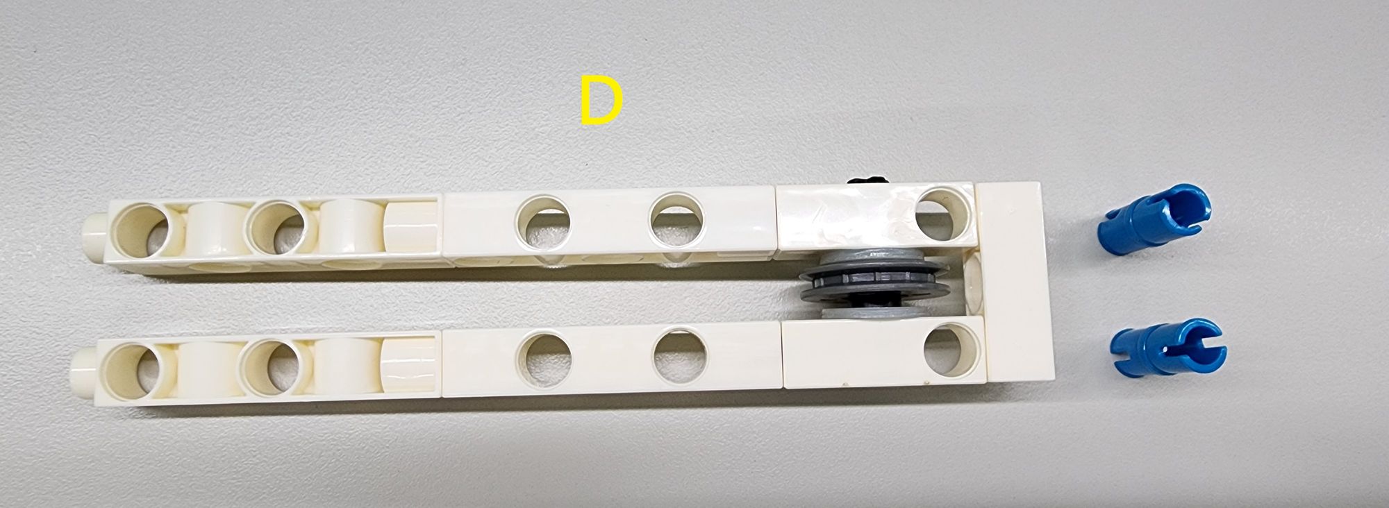
Assemble all the parts except the C-AXLE CONNECTOR accordingly to create Part D (Figure 10).
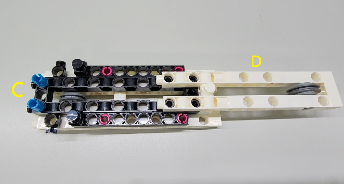
Next, connect the B-SHORT PEG of Part D to Part C as shown, completing the bracket installation. Finally, attach the two C-AXLE CONNECTOR to Part C to stabilize the inner blade (Figure 11).
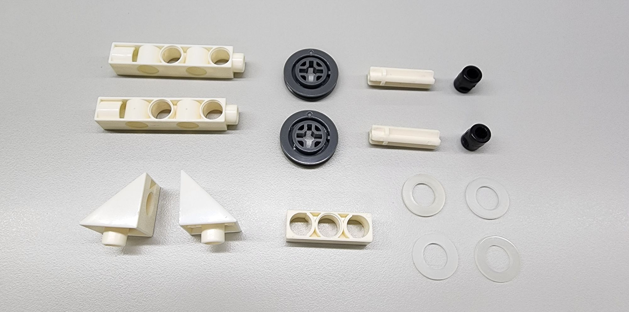
Step 5: Assembling Additional Components
For this step, you’ll need the following components:
- C-3 HOLE RODs
- C-5 HOLE DUAL ROD
- C-OD23mm PULLEY
- C-MOTOR AXLE
- C-WASHER (M8×16)
- B-TRIANGLE
- B-SHORT PEGs (Figure 12)
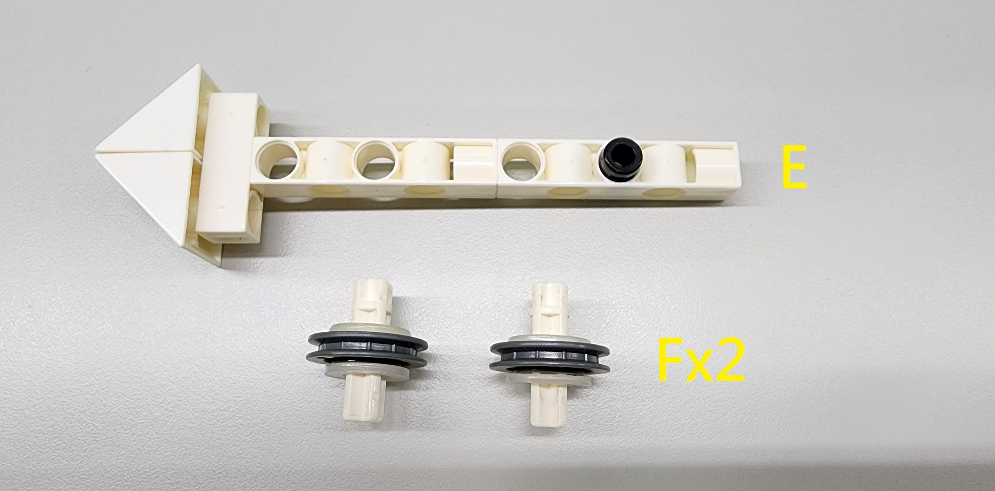
Assemble these parts accordingly to create one Part E and two Part F components (Figure 13).
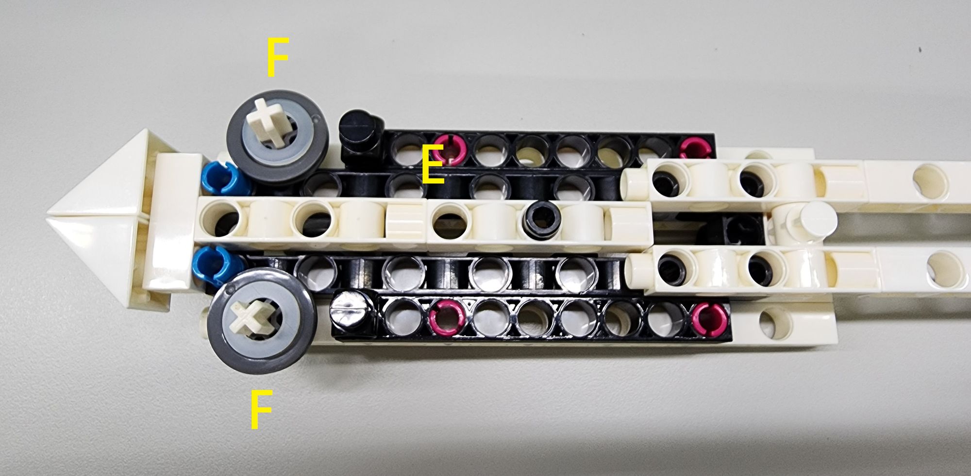
Next, attach Parts E and F to Part C as shown (Figure 14). Part Eserves as the inner blade of the hidden dagger, while Part Fforms the fixed pulley structure. Once the cotton rope is installed, the inner and outer blades will be able to slide smoothly.
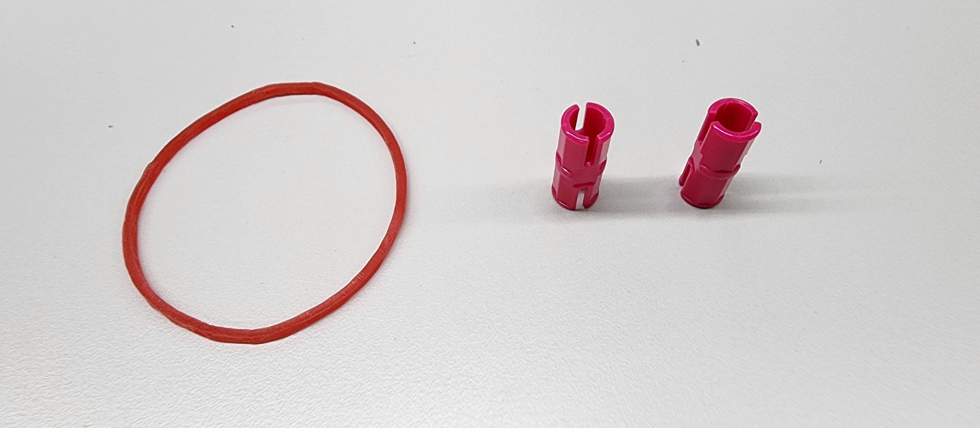
Step 6: Installing the Retraction Mechanism
For this step, you will need:
- Rubber band
- C-STATIC AXLE CONNECTOR (Figure 15)
Attach the C-STATIC AXLE CONNECTOR to Part D as shown, then loop the rubber band through Part E and secure it onto the C-STATIC AXLE CONNECTOR (Figure 16). The elastic force of the rubber band allows the blade to automatically retract into the base without any external force.
Step 7: Installing the Cotton Rope
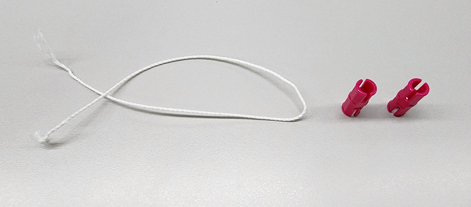
For this step, you will need:
- Cotton rope (about 28 cm)
- C-STATIC AXLE CONNECTOR (Figure 17)
First, thread the cotton rope through the hole in Part E, as shown. Then, pull the rope forward and place it into the groove at the center of the C-OD23mm PULLEY. Ensure the rope is slightly taut—if it’s too loose, it may affect the blade’s extension and retraction mechanism (Figure 18).
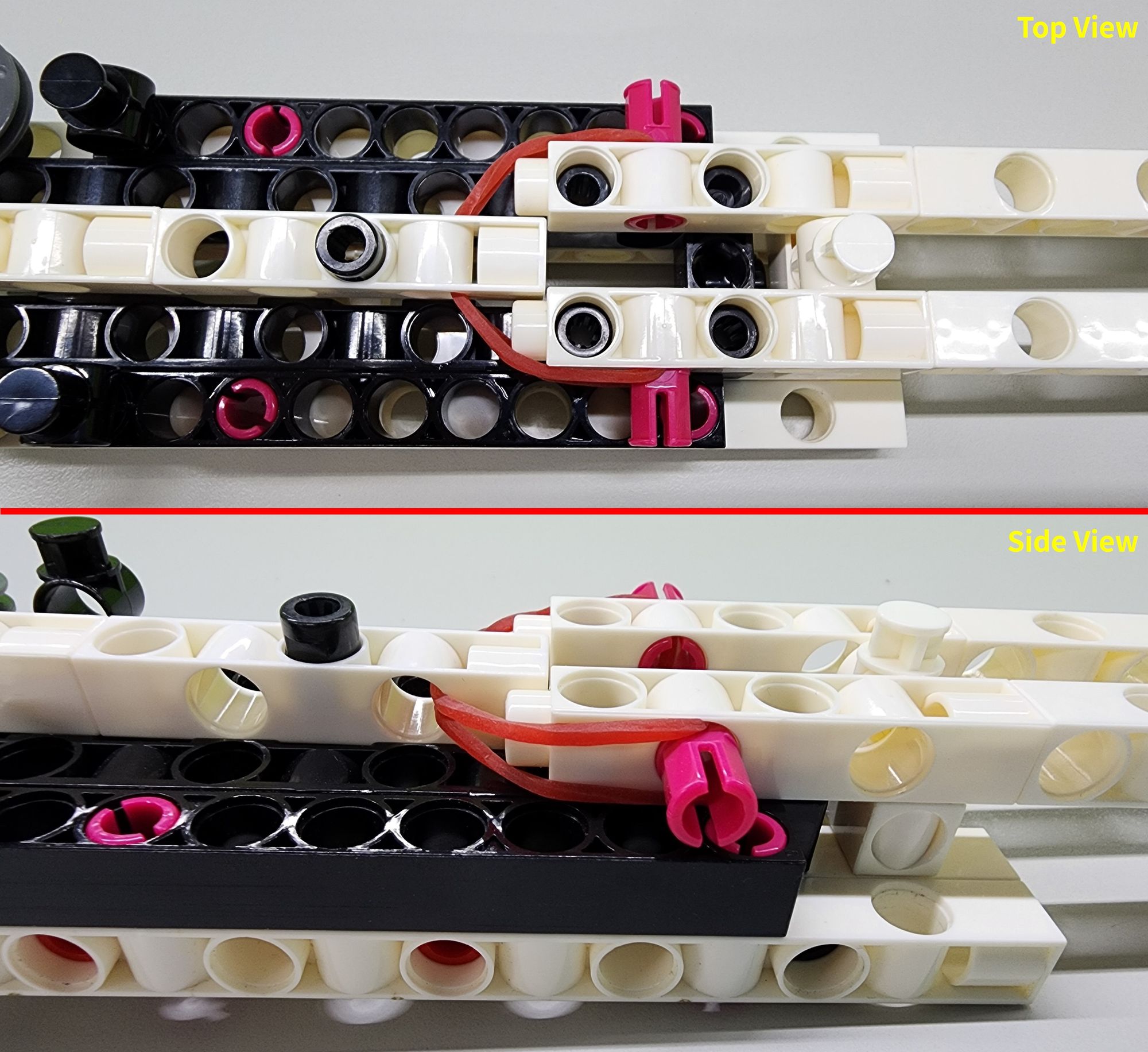
Next, secure the cotton rope by aligning the gap of the C-STATIC AXLE CONNECTOR with the rope and pressing it fully into the C-1 HOLE CONNECTOR. This completes the linkage mechanism for the inner and outer blades (Figure 19).
If you're concerned about the rope not being firmly secured, you can tie a knot at each end of the cotton rope before pressing the C-STATIC AXLE CONNECTOR to ensure a more secure attachment.
Finally, we need to enclose the inner blade inside the outer blade. Take the remaining Part C from Step 3 and connect its B-SHORT PEG to Part D as shown (Figure 20). Be sure not to pinch the rubber band when making this connection.
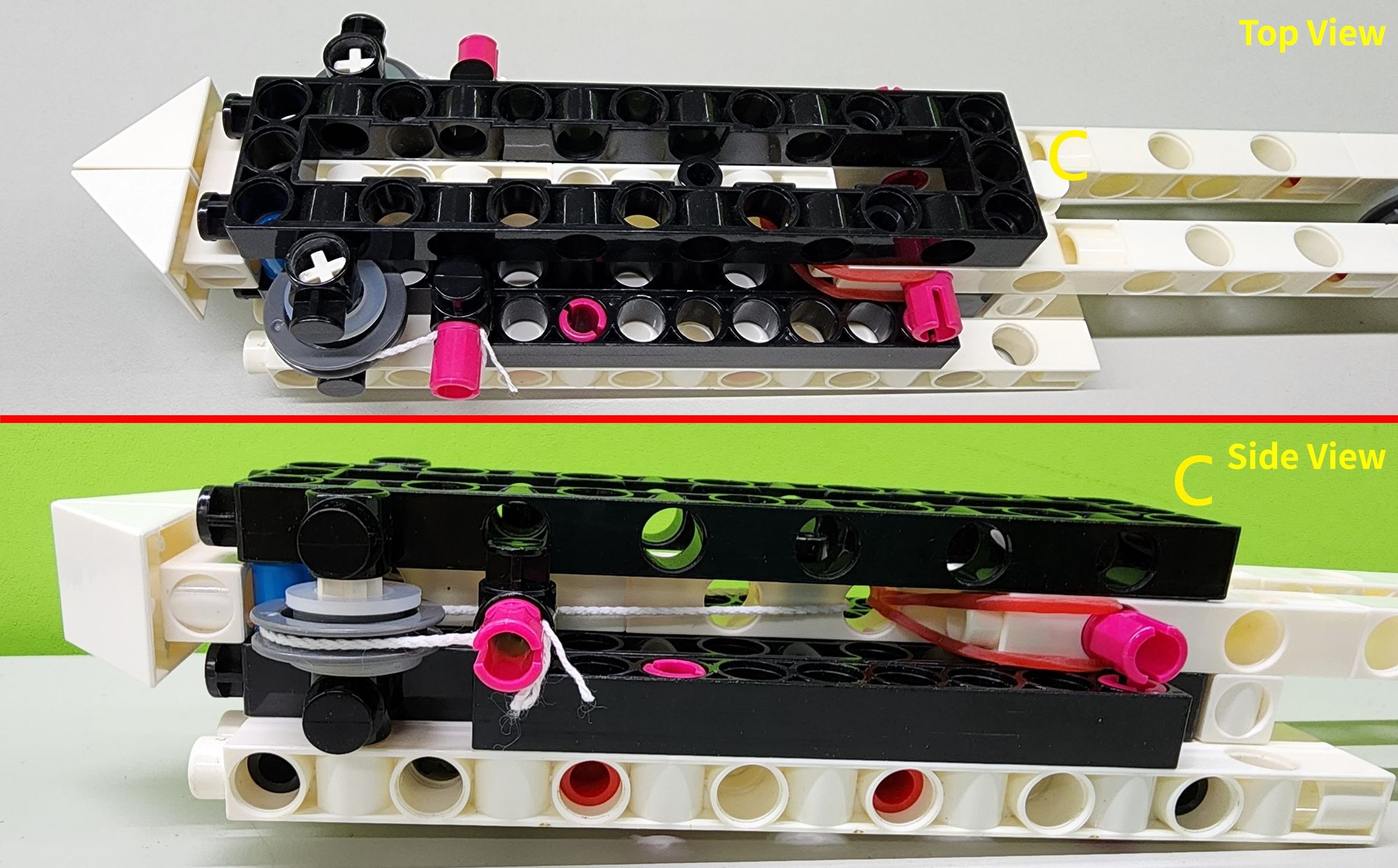
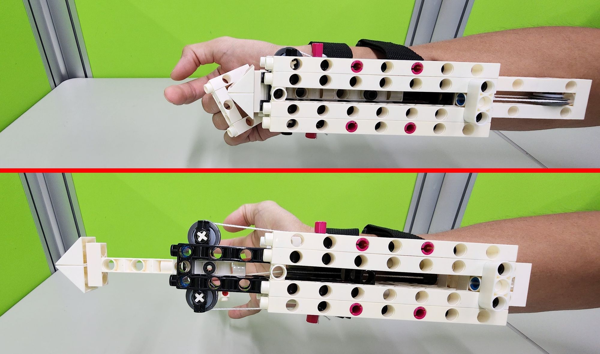
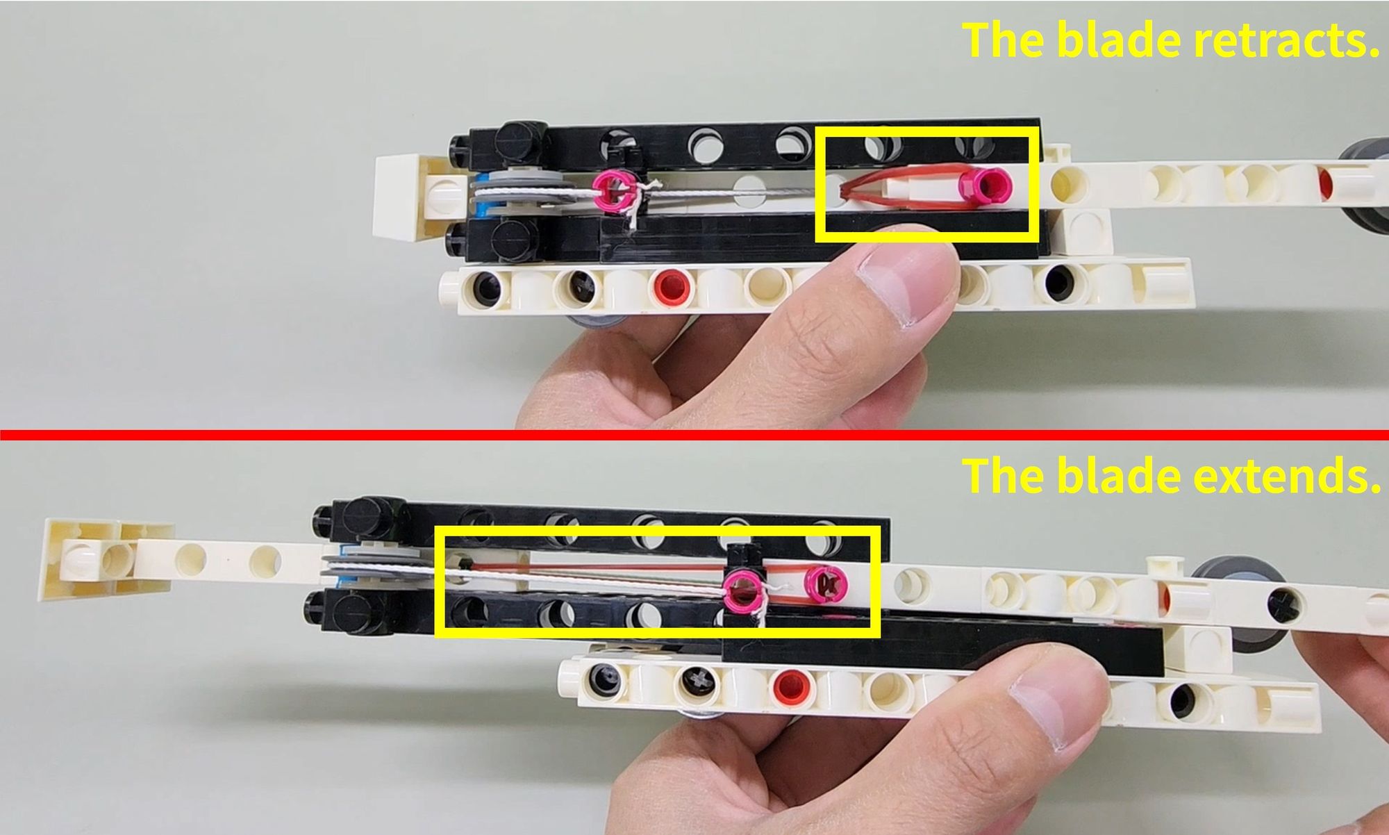
This completes the assembly of the inner and outer blades. Now, we can test the linkage mechanism by pushing the bracket or outer blade forward and observing if the inner blade extends as well, creating the desired blade extension effect (Video 1).
Once the test is complete, you can begin assembling the upper base.
Step 8: Assembling the Upper Base
For this step, you will need the following components:
- C-15 HOLE DUAL ROD
- C-9 HOLE ROD
- C-3 HOLE ROD
- C-1 HOLE CONNECTOR
- C-LONG PEG
- B-SHORT PEG
- C-STATIC AXLE CONNECTOR (Figure 21)
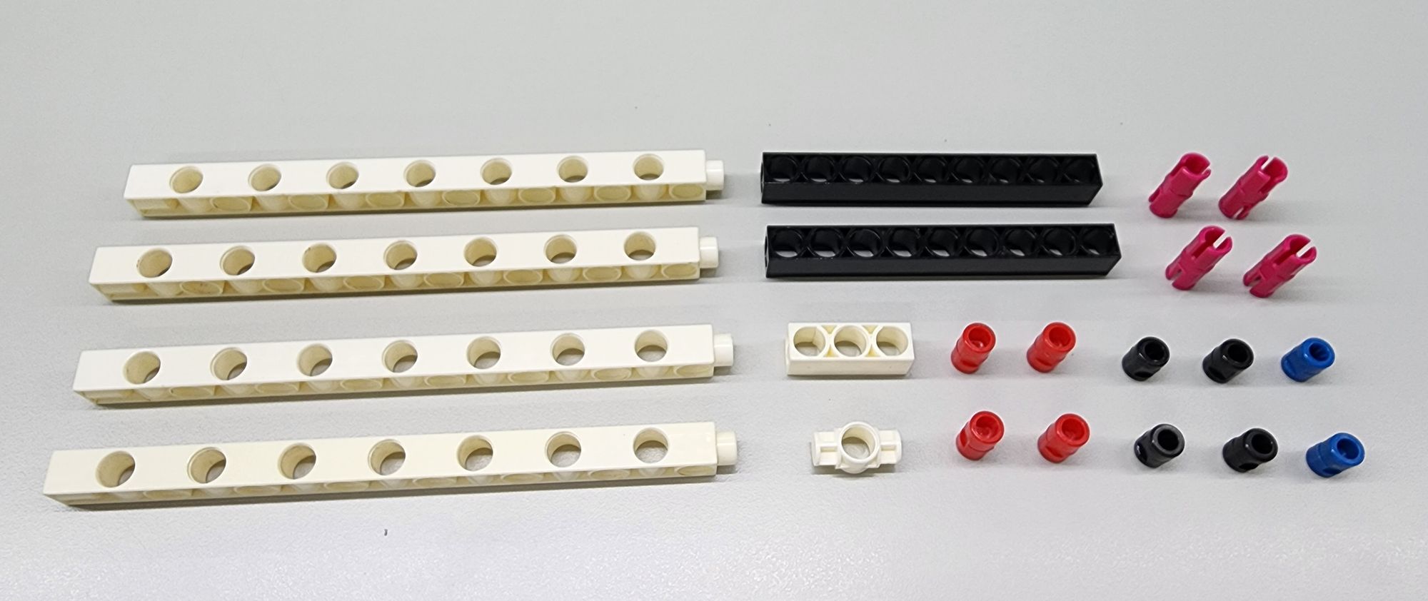
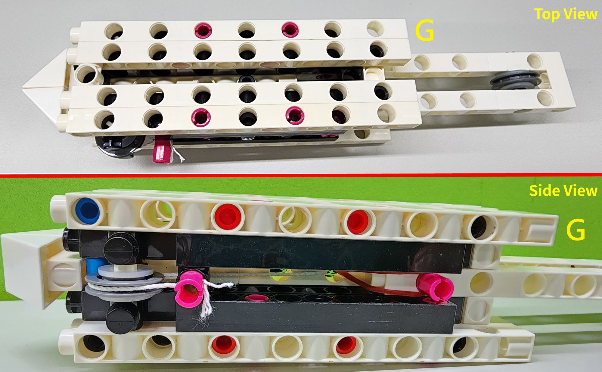
Assemble these parts as shown to complete Part G (Figure 22).
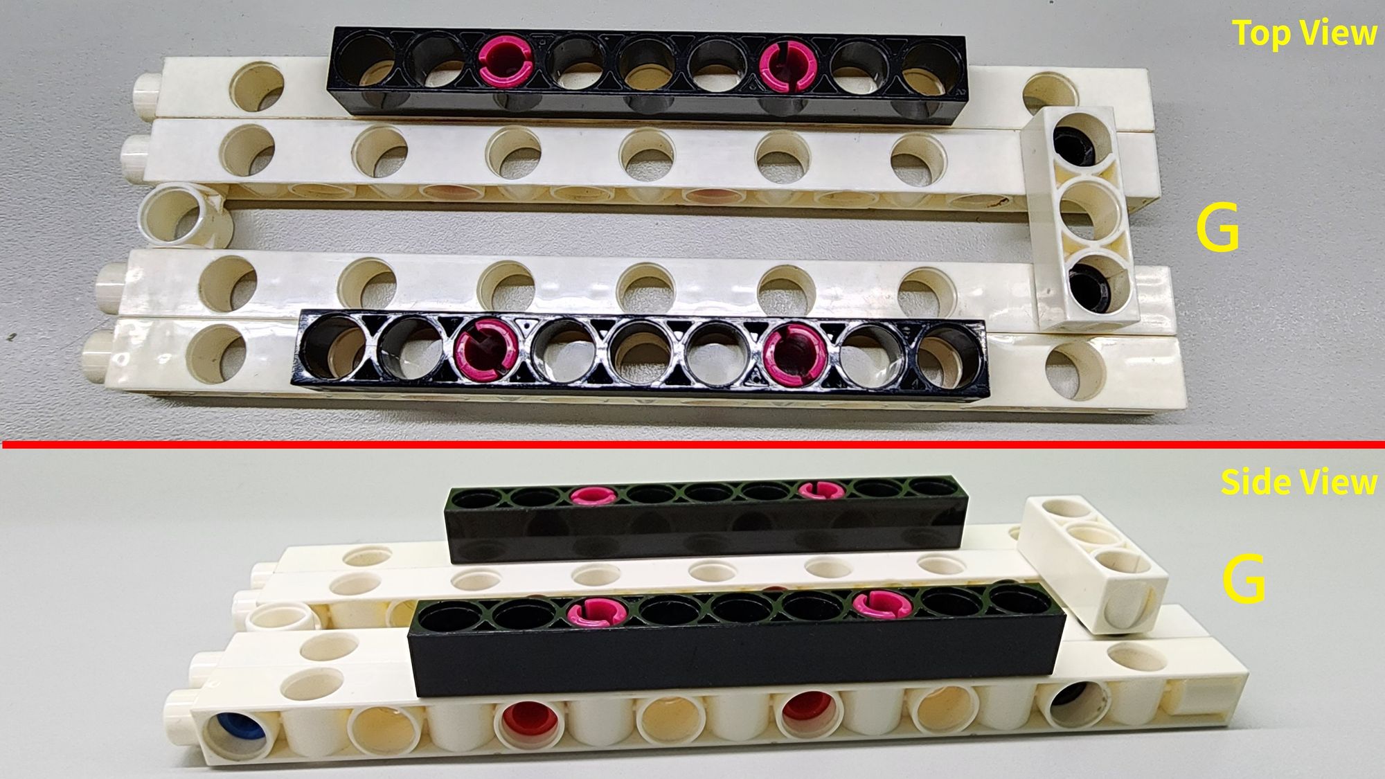
Next, connect Part G to the C-1 HOLE CONNECTORs of Parts A and B as shown in the diagram (Figure 23), completing the installation of the upper base.
Step 9: Assembling the Handle and Pulley Mechanism
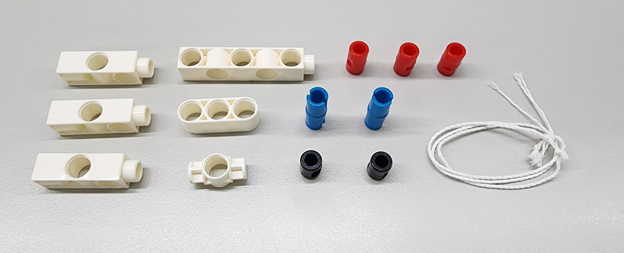
For this step, you will need the following components:
- C-3 HOLE DUAL ROD
- C-5 HOLE DUAL ROD BOTTOM CLOSED
- C-3 HOLE ROUND ROD
- C-1 HOLE CONNECTOR
- C-LONG PEG
- B-SHORT PEG
- C-AXLE CONNECTOR
- Cotton rope (about 35 cm) (Figure 24)
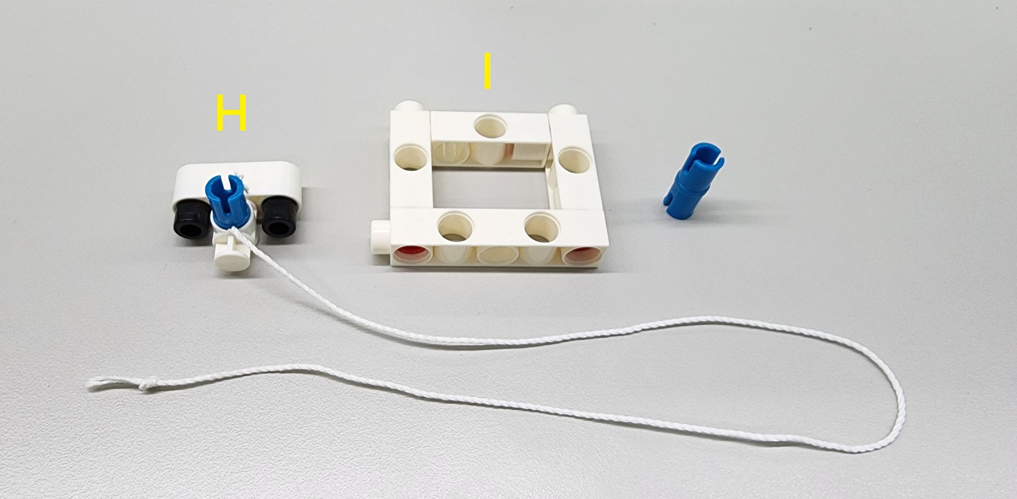
Assemble the parts to create Parts H and I(Figure 25). Part H is used to secure the cotton rope for the movable pulley, while Part I serves as the handle to be placed on your finger.
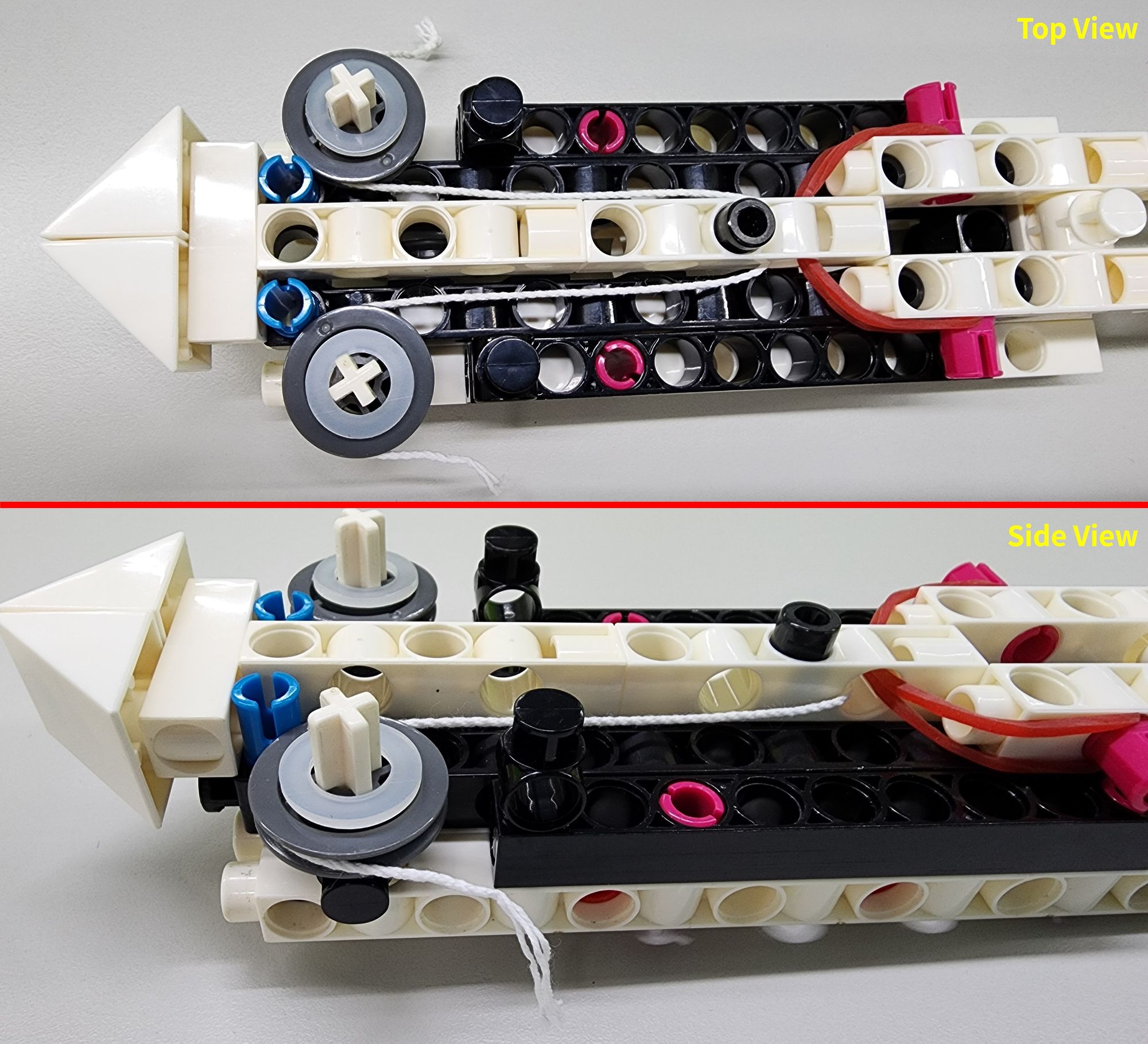
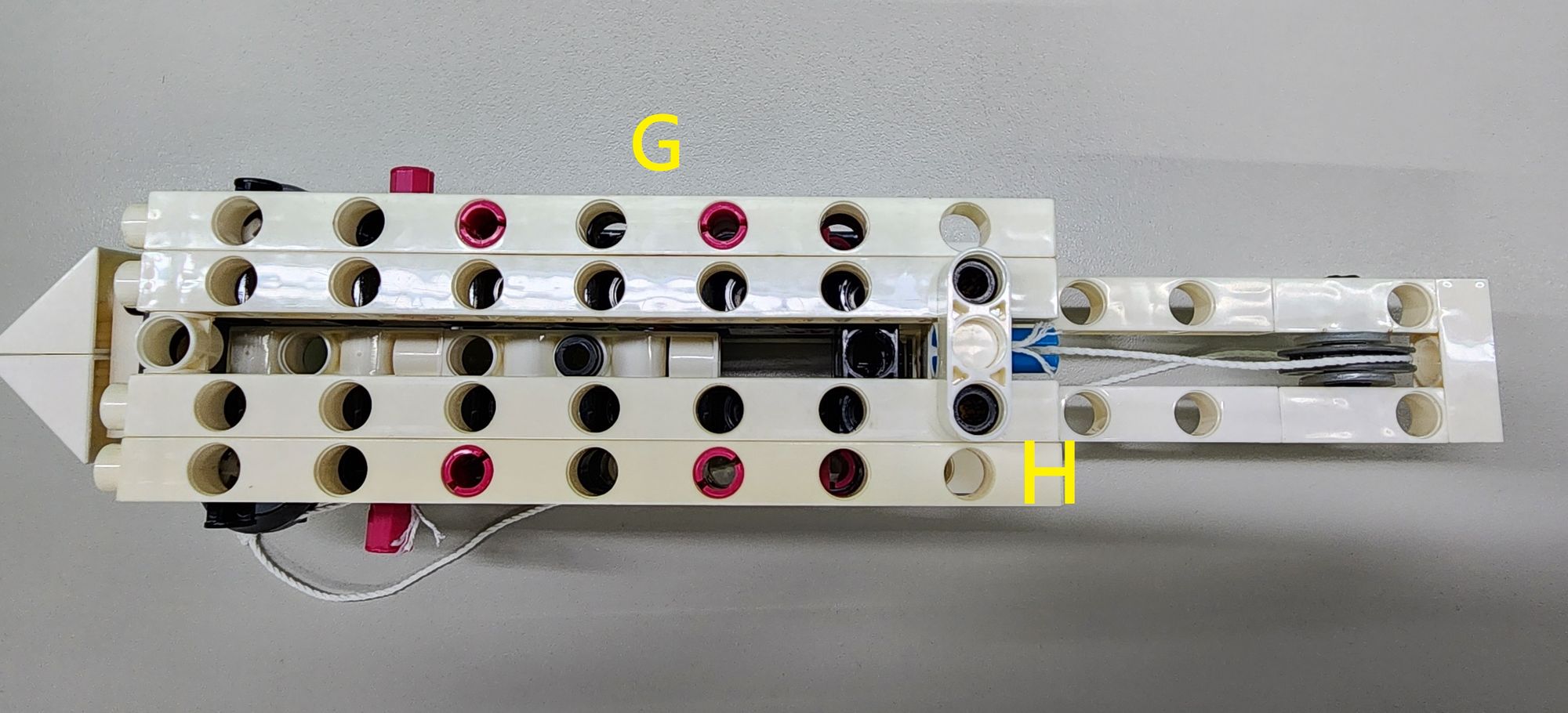
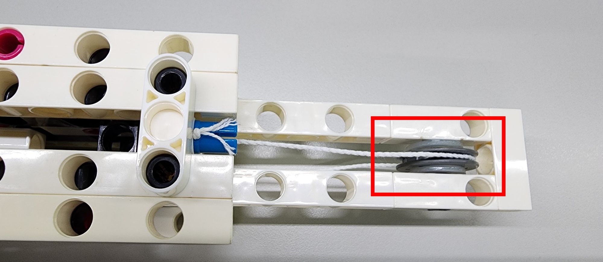
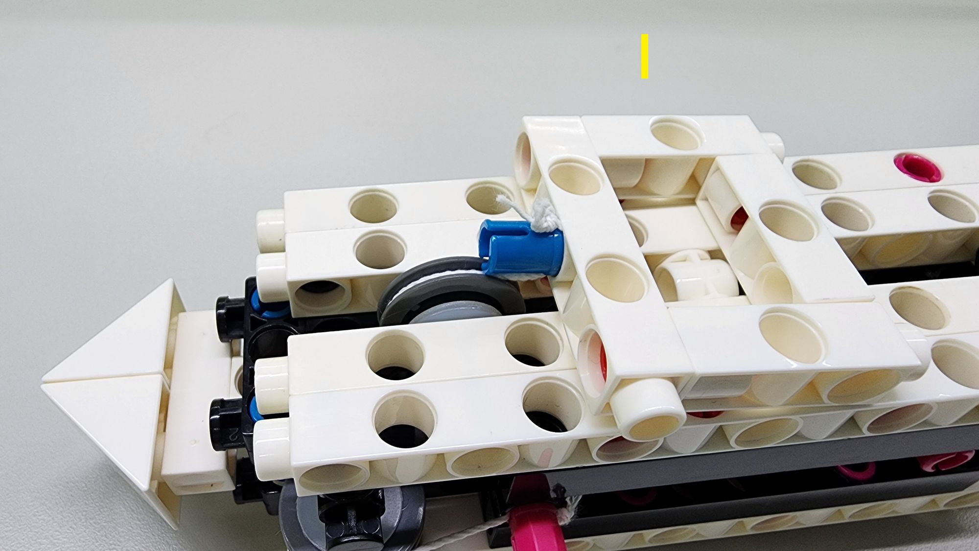
Next, attach Part H to Part G(the upper base) as shown to secure the cotton rope for the movable pulley (Figure 26). Make sure the cotton rope is properly inserted into the groove at the center of the C-OD23mm PULLEY (located in Part D) and extends in the opposite direction (Figure 27).
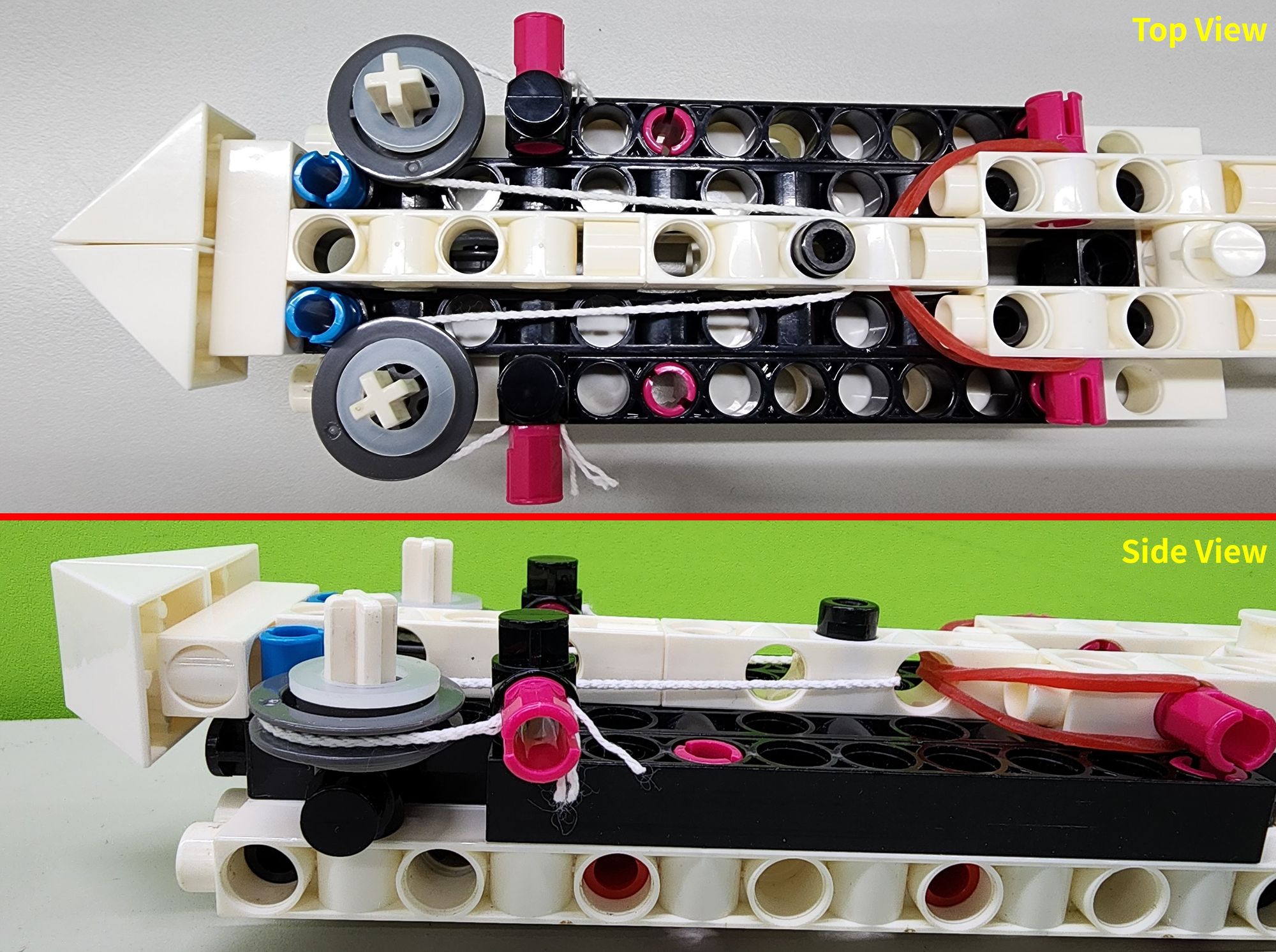
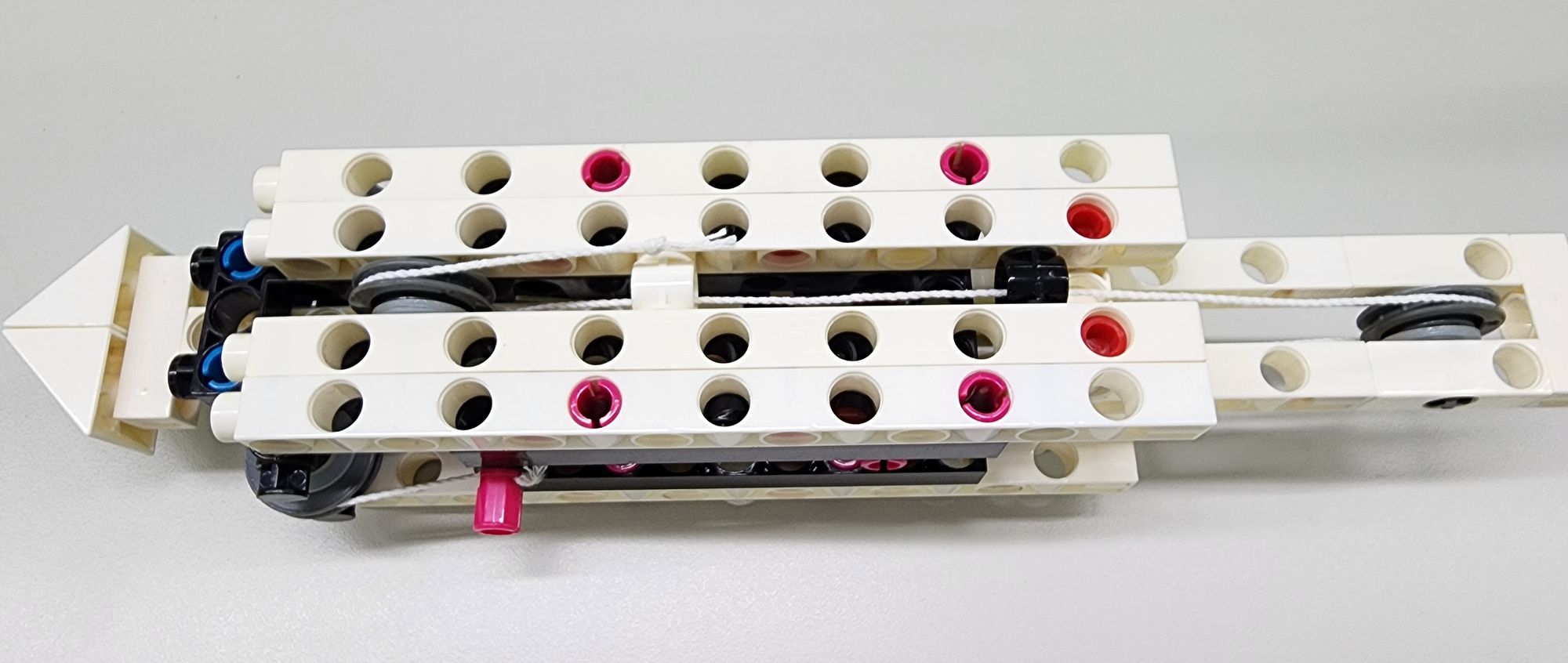
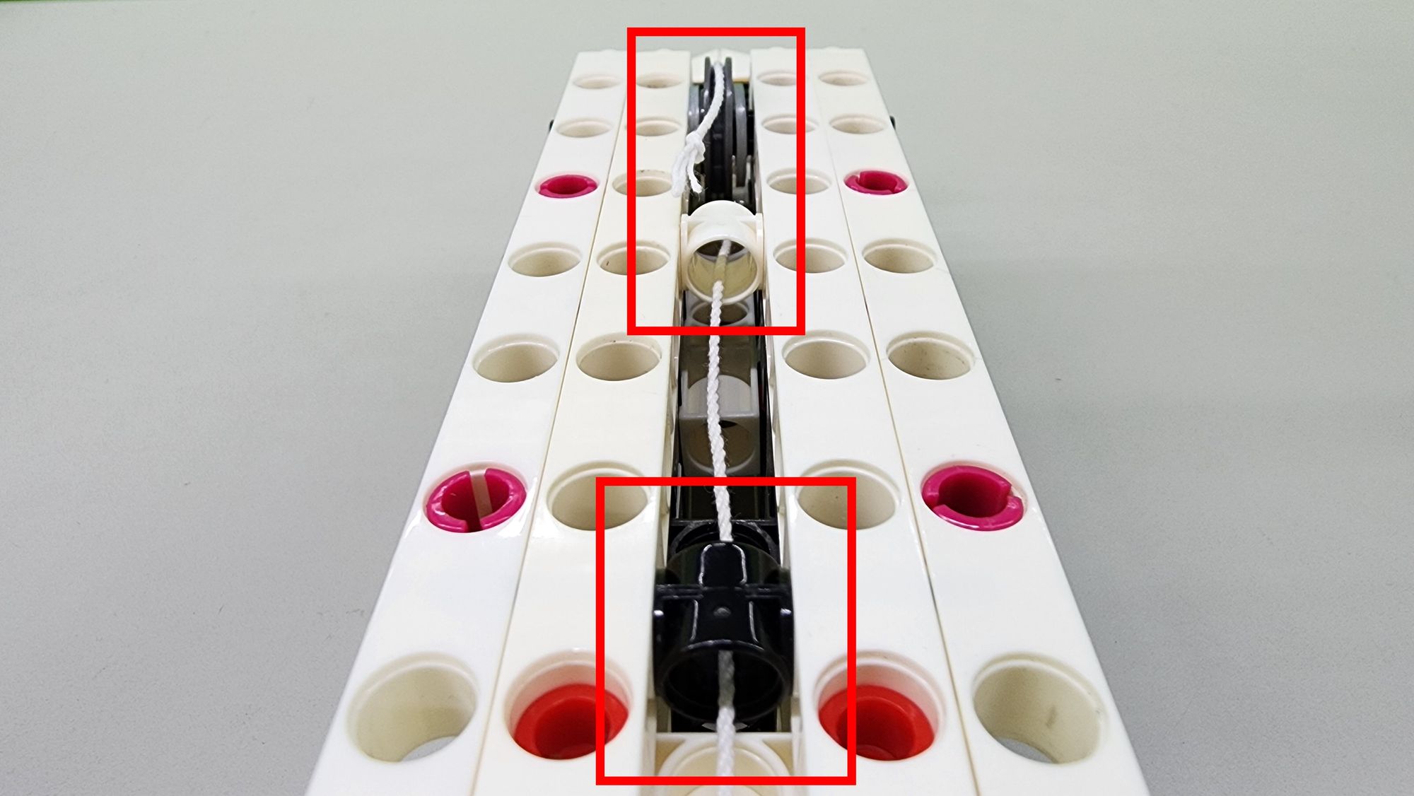
Next, we need to hide and straighten the cotton rope. First, turn the Hidden Blade model over. Then, thread the cotton rope through the two C-1 HOLE CONNECTOR in the lower base as shown in the diagram, ensuring the rope is properly inserted into the groove at the center of the C-OD23mm PULLEY (located in the lower base) (Figures 28 and 29). Once completed, the cotton rope should form an S shape. This step may be a bit tricky, so it’s recommended to use needle-nosed pliers or tweezers for better precision.
Finally, take the remaining C-AXLE CONNECTOR and attach the cotton rope to Part I as shown (Figure 30), completing the fixation of the handle.
Next, let's conduct a test to verify whether the movable pulley mechanism can successfully drive the bracket. Pull the handle upward or backward and observe if the bladeextends smoothly (Video 2).
Step 10: Fixing the Hidden Blade on the Hand
For this step, you will need the following components:
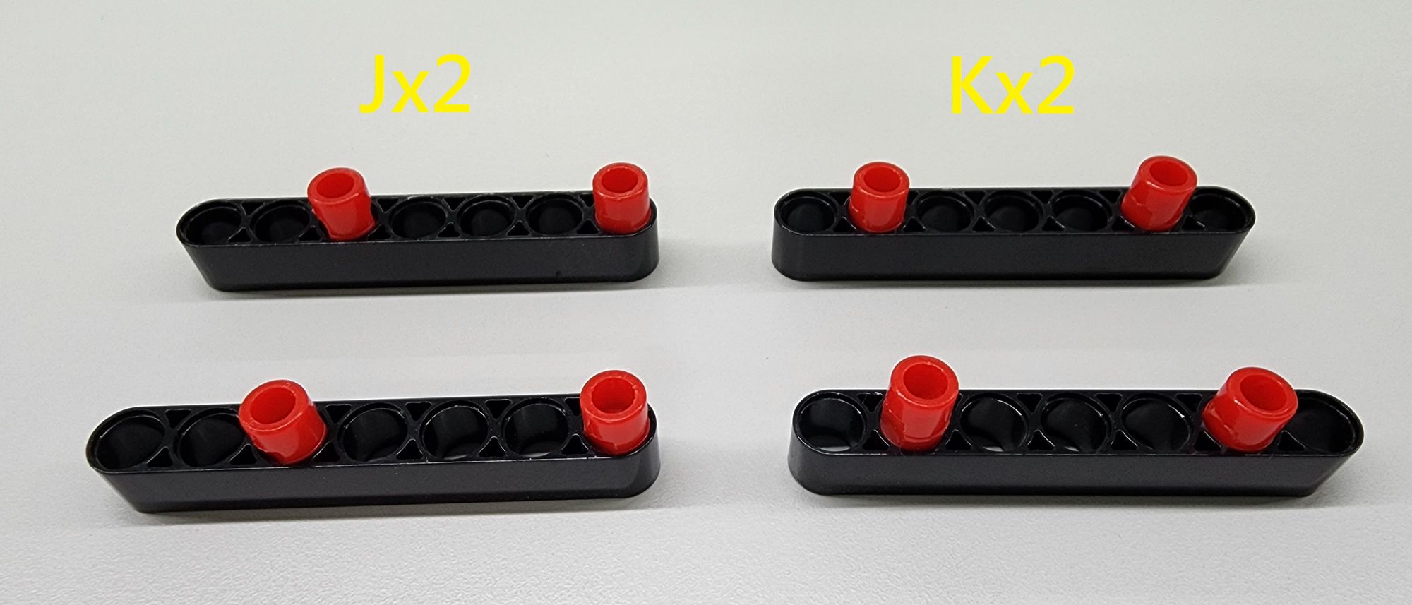
- C-7 HOLE WIDE PROLATE ROD
- C-LONG PEG (Figure 31)
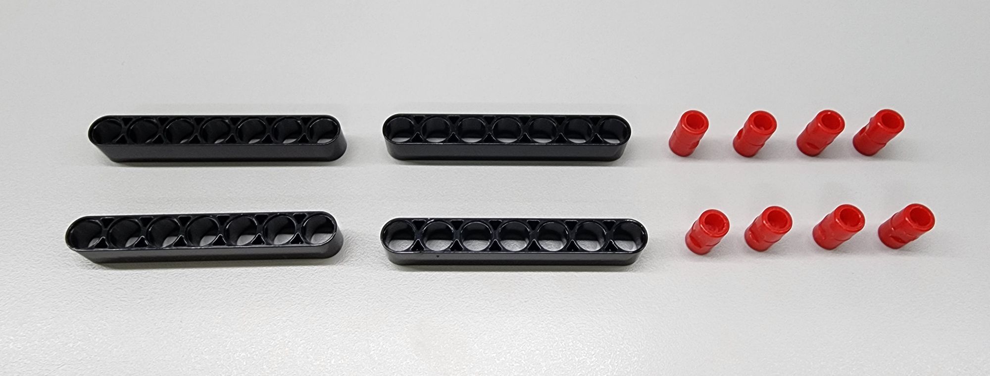
Assemble the parts to create two Parts Jand two Parts K (Figure 32). These will be used to secure the hidden blade on the hand.
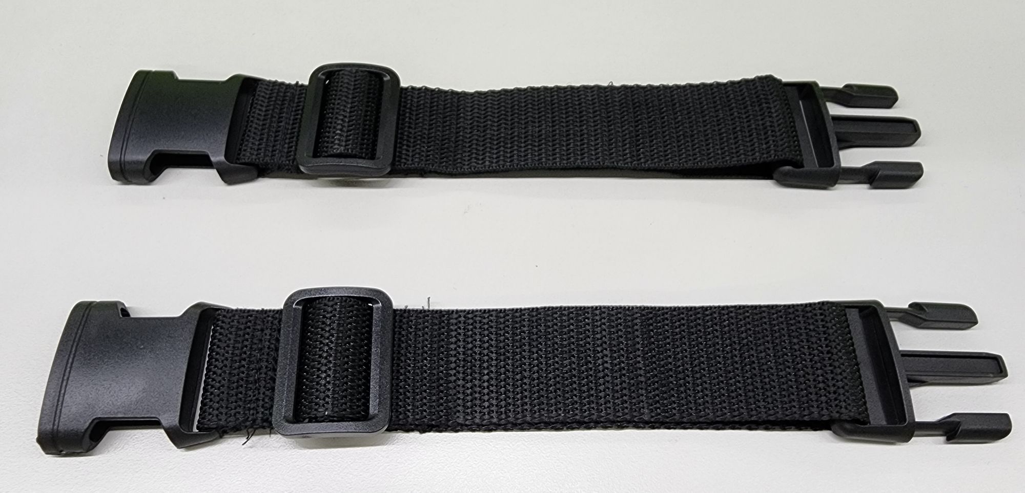
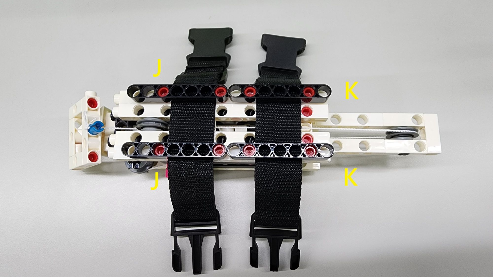
Finally, you will need two luggage straps (Figure 33), which can be purchased at a hardware store or online. Place the luggage straps on the lower base as shown in the diagram and secure them using Parts J and K(Figure 34).
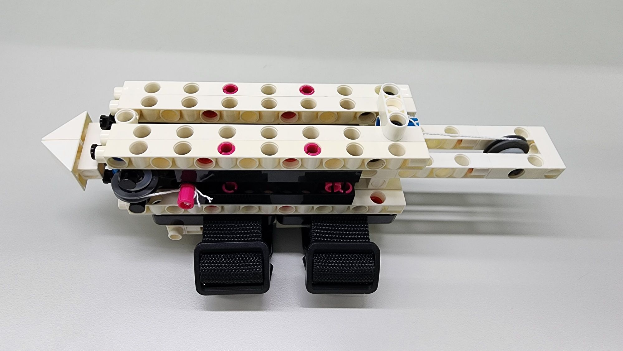
This completes the assembly of the hidden blade (Figure 35). Now, let’s see how to operate it!
◆ Model Operation
First, wrap the luggage strap around your arm and fasten it. Then, insert your fingers into the handle. When you pull the handle upward using your wrist and fingers, the blade will extend from the base (Videos 3 and 4), just like a real hidden blade!
◆Conclusion
The Hidden Blade model created today is inspired by the inventions featured in the game Assassin's Creed. Beyond games, many imaginative inventions can also be found in creative media such as animations, comics, and movies. These works, set in fictional worlds, have the freedom to step outside the boundaries of reality, giving rise to unique and captivating designs.
In the future, Teacher Raccoon will continue to explore the potential of building blocks to bring more inventions and concepts from games and animations into the real world, so stay tuned for more exciting projects!
That’s all for today’s share. If you enjoyed this article, please remember to share it with Teacher Raccoon. See you next time. Bye!
◆Scientific Principles
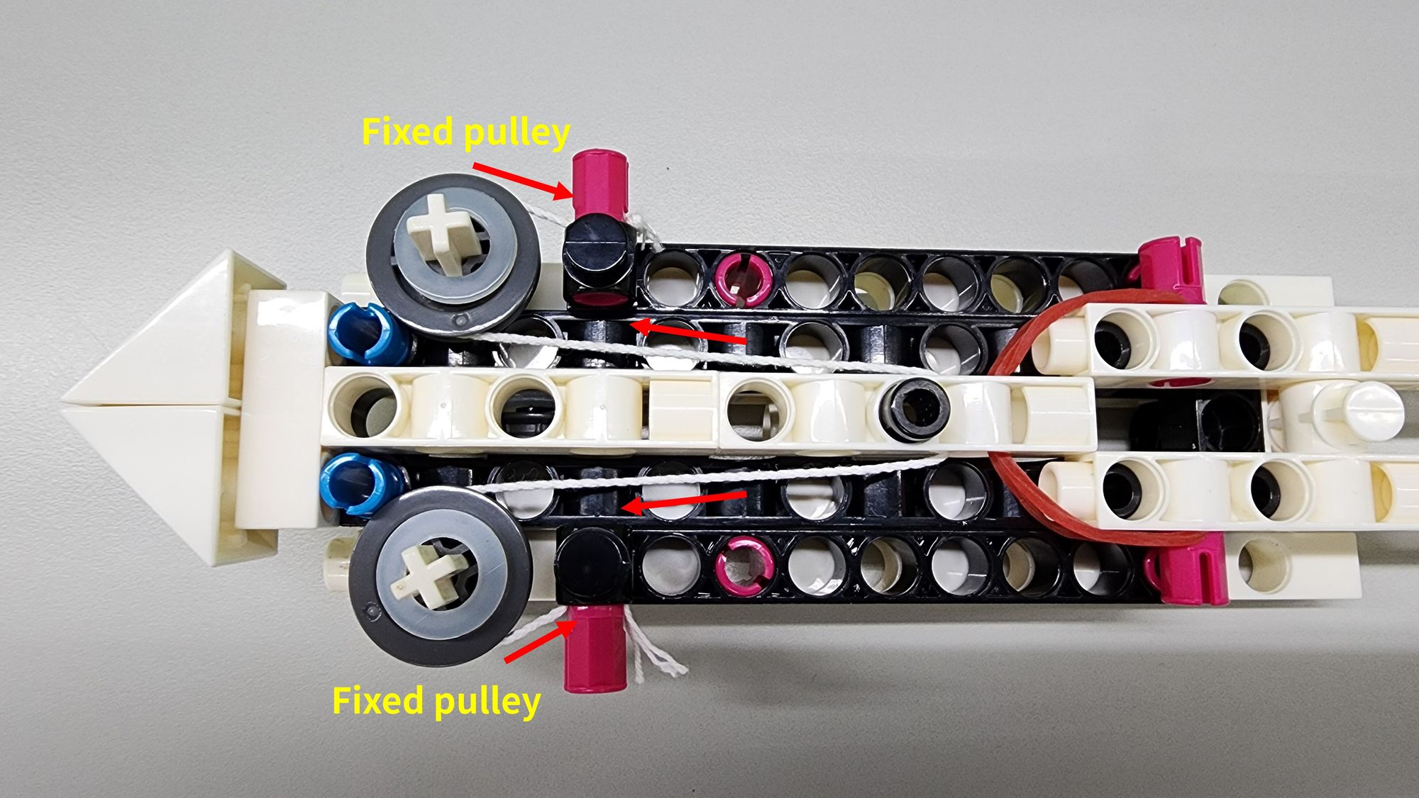
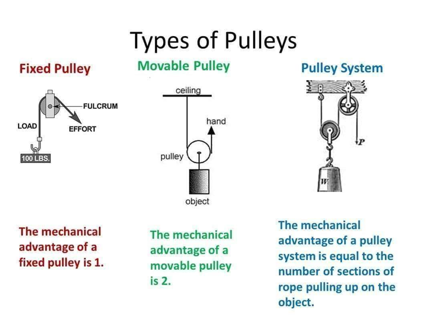
The Hidden Blade model incorporates the scientific principles of fixed pulley mechanisms, movable pulley mechanisms, tension, and elastic force. We use a cotton rope and a fixed pulley mechanism to connect the inner and outer blades. When the bracket and outer blade are pushed forward, the cotton rope experiences tension (shown by the red arrow). This tension is redirected through the fixed pulley, which then pushes out the inner blade, creating the effect of the blade extending and retracting (Figure 36).
The movable pulley is used on the bracket. Unlike the fixed pulley, it helps to reduce the effort required, making it easier to pull the cotton rope without straining the wrist and fingers. This design minimizes the physical effort needed, lightening the load on your hand (Figure 37).
Finally, elastic force is used to retract the blade. When we pull the cotton rope to extend the blade, the rubber band deforms and stores energy. Once we stop applying force, the rubber band releases this stored energy, returning to its original state and pulling the blade back into the base (Figure 38).
◆ NGSS Curriculum:
3-5-ETS1-1Define a simple design problem reflecting a need or a want that includes specified criteria for success and constraints on materials, time, or cost.
MS-PS2-2Plan an investigation to provide evidence that the change in an object’s motion depends on the sum of the forces on the object and the mass of the object.
3-PS2-4 Define a simple design problem that can be solved by applying scientific ideas about magnets.
MS-PS2-2Plan an investigation to provide evidence that the change in an object’s motion depends on the sum of the forces on the object and the mass of the object.
#Gigo#Gigo Lab#Learning Lab#Fun Lab
◆參考資料:
 Contributors to Assassin’s Creed Wiki
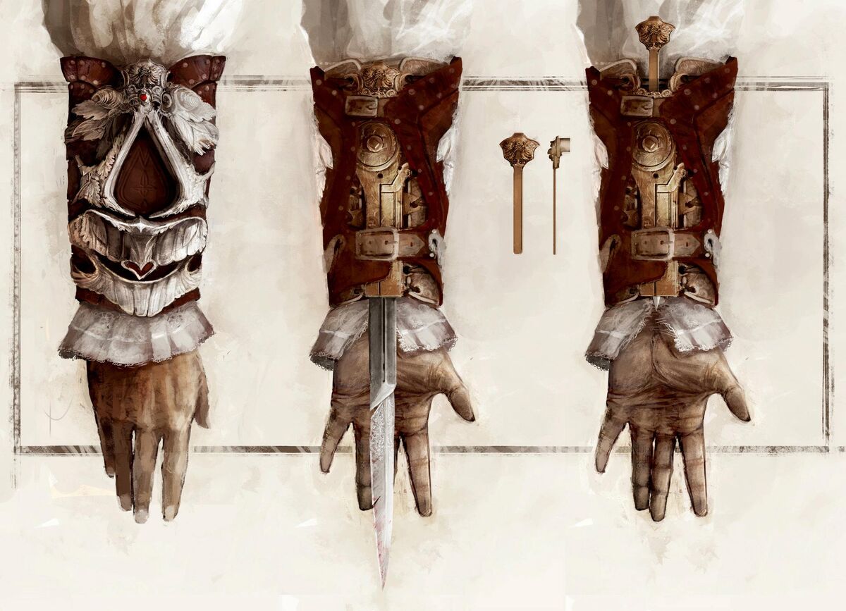

 Contributors to Wikimedia projectsContributors to Wikimedia projects
 Contributors to Wikimedia projects
 Contributors to Wikimedia projects
Please sign in to vote.