Science in daily life: EP7 – A Useless Box

Hey everyone, it's Teacher Raccoon! Our world is filled with countless inventions that serve practical purposes, like the telephone, electric light, and washing machine. These inventions greatly enhance our lives. However, today I'm going to teach you how to make something completely useless—an utterly pointless contraption known as a useless box.
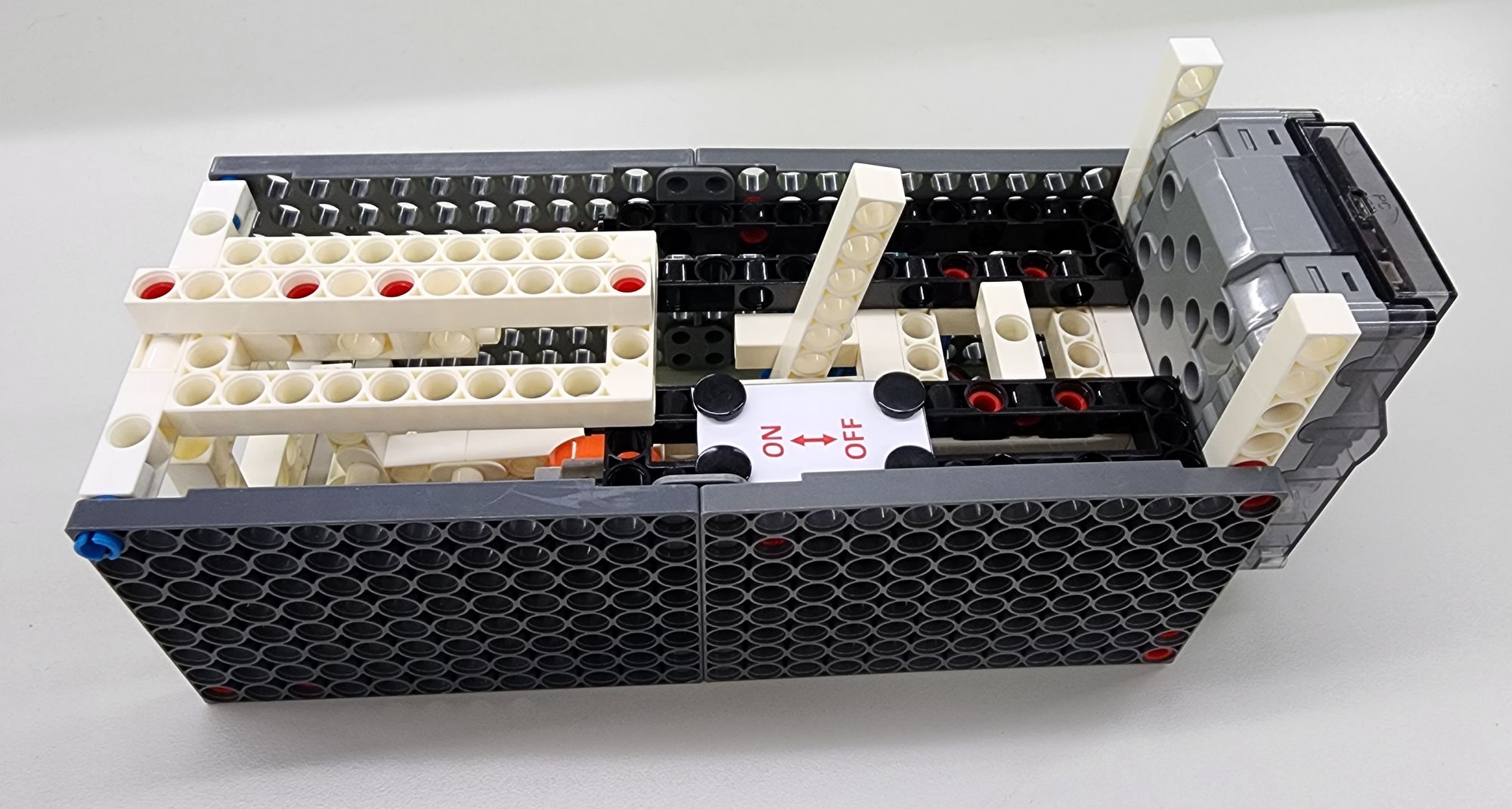
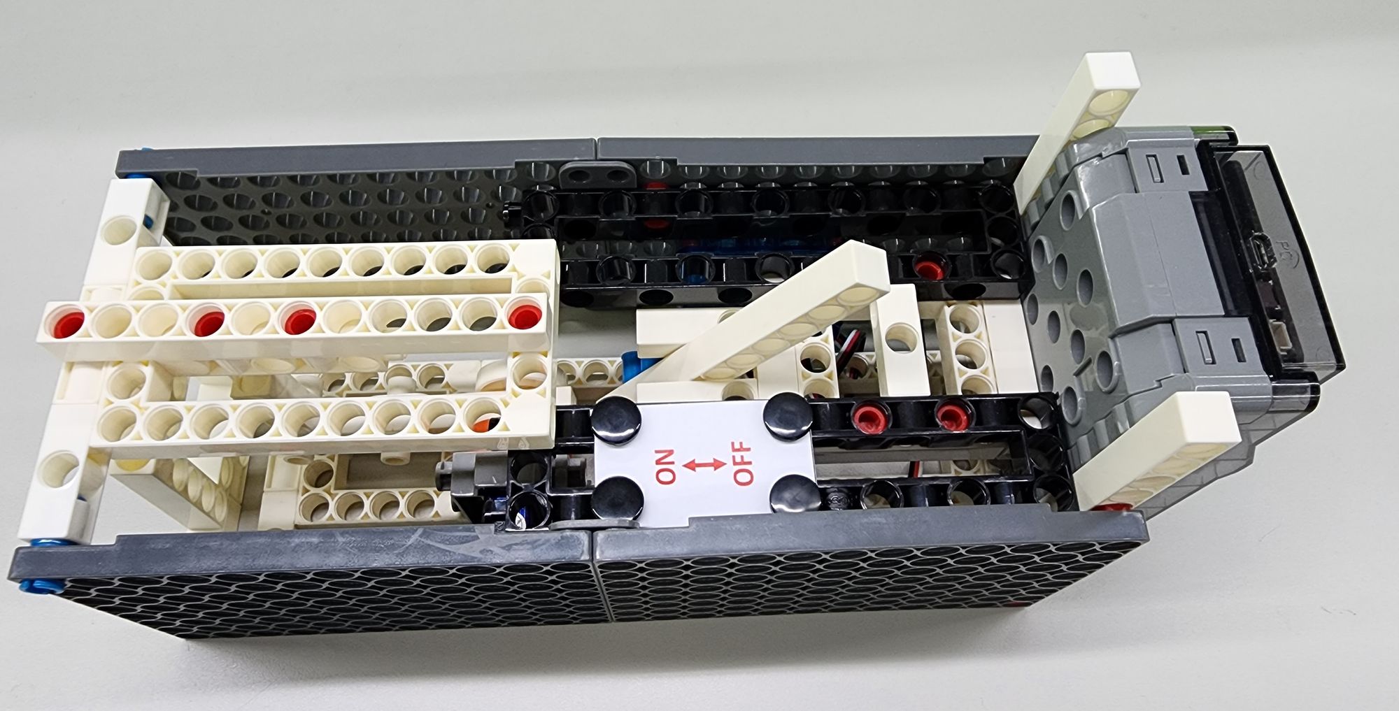
The useless box, also called the useless switch, is exactly what it sounds like—a box with a two-stage toggle switch on top. When we flick the switch on, it triggers a hammer inside the box to turn the switch back off. In other words, the purpose of turning on the switch is simply to turn it off (check out Video 1). With such a quirky design, it's no wonder it's earned the name "useless box." Now, let me guide you through the step-by-step process of making your own useless box!
◆Assembly Steps:
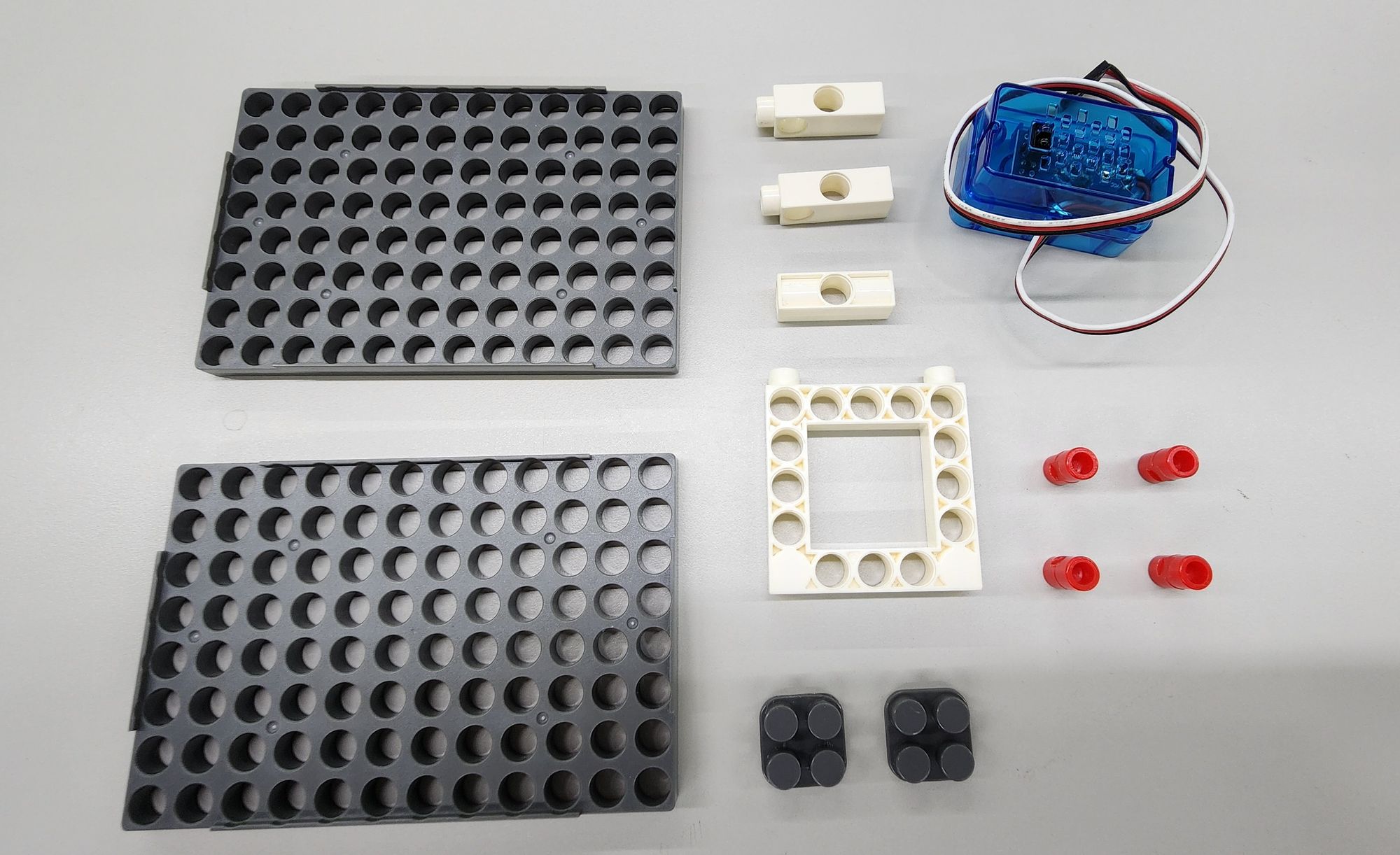
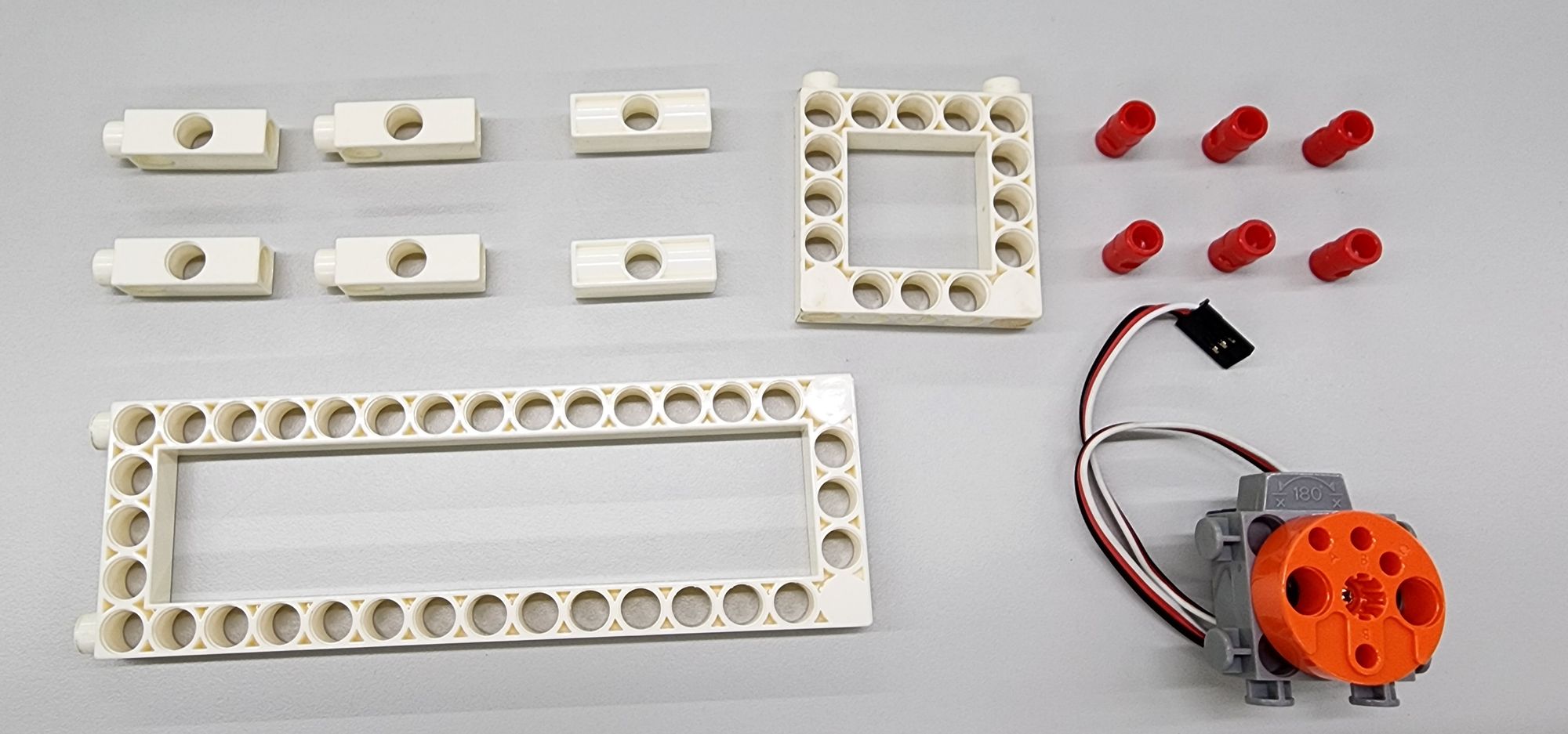
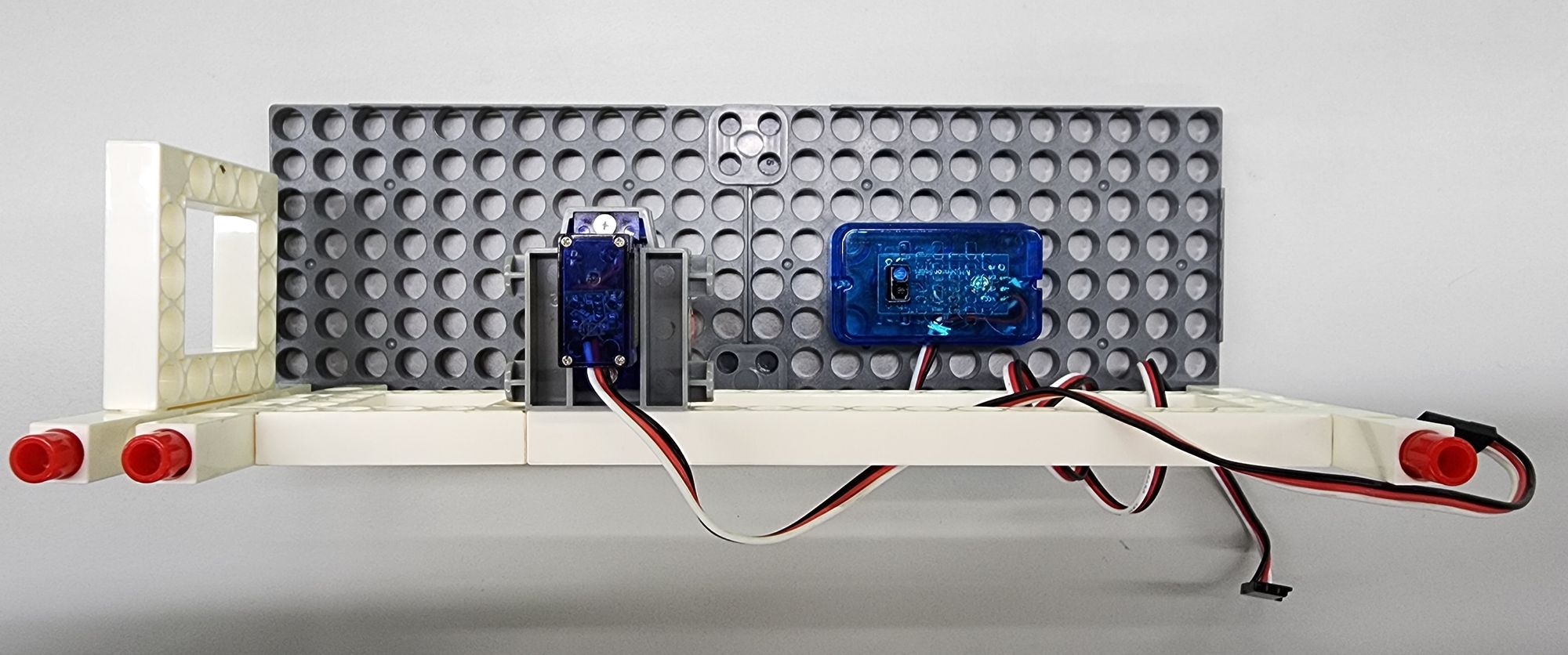
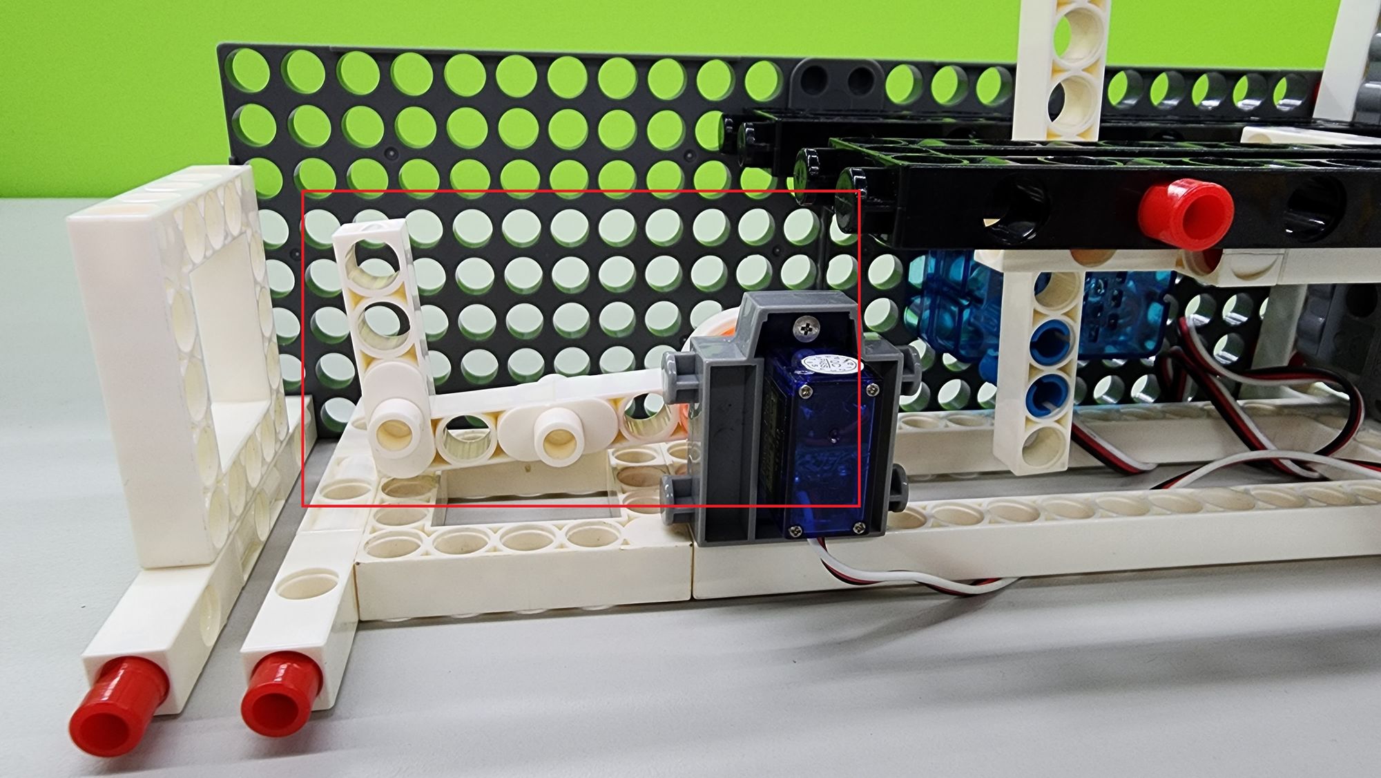
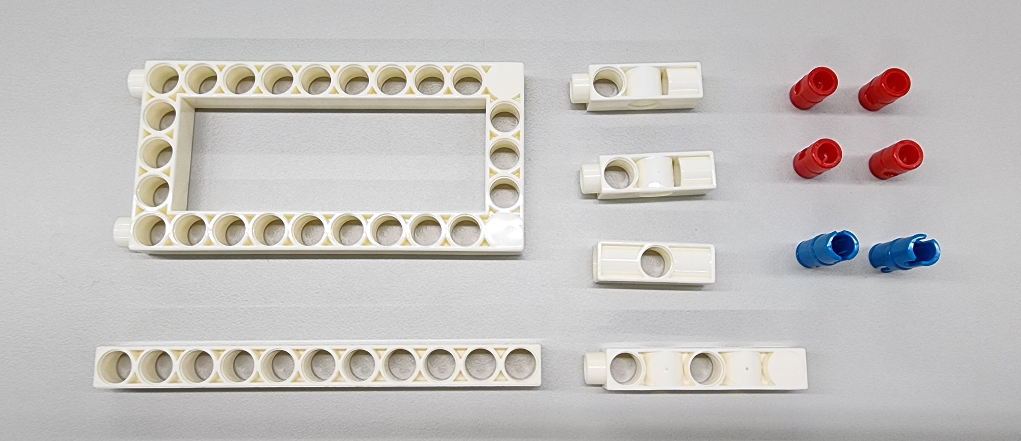
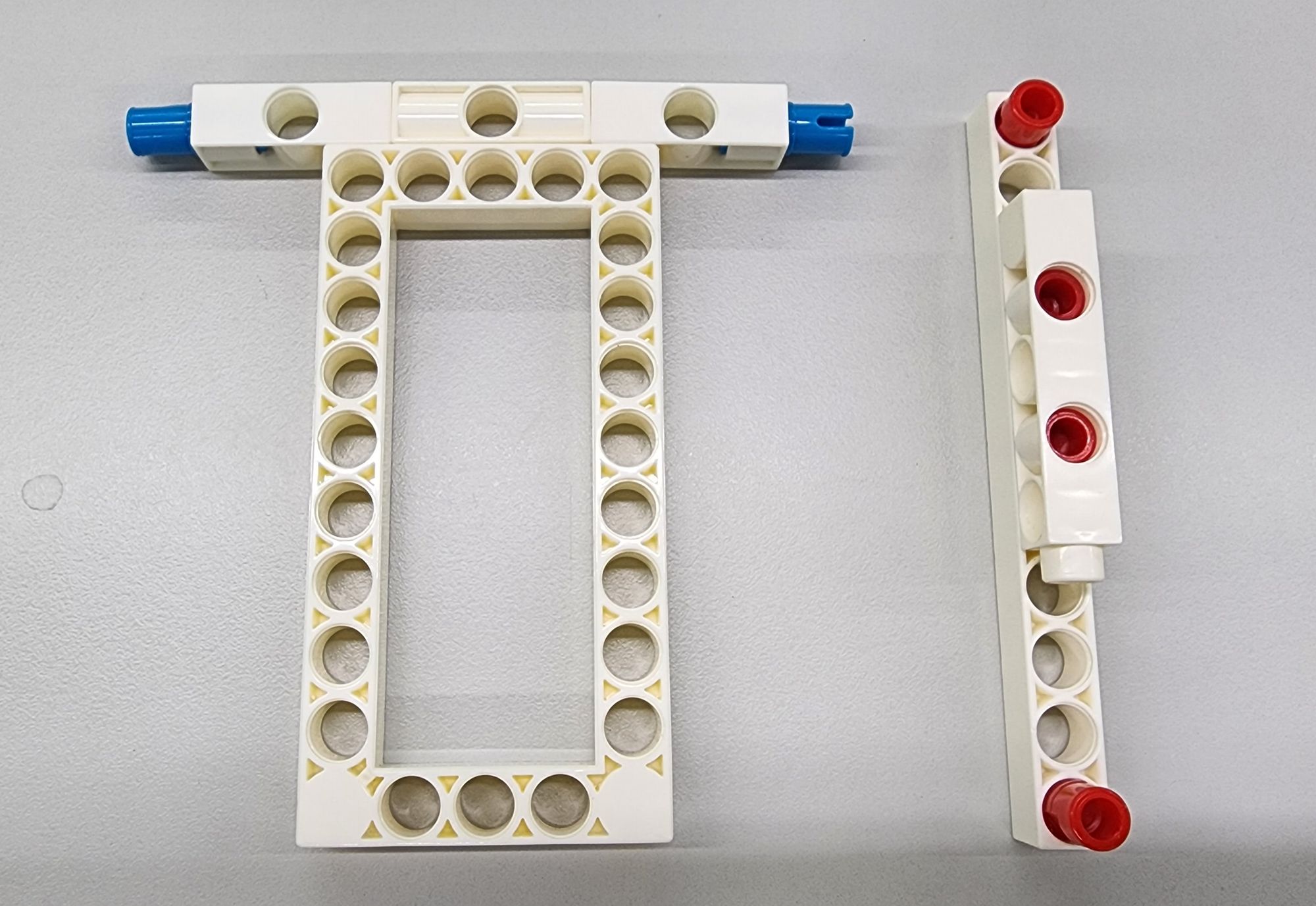
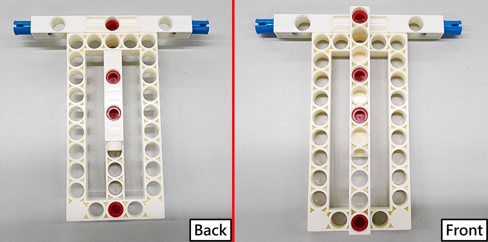
Step 1: We make the baffles on the right and rear of the useless box. We need to use the C-BASE GRID, C-5X5 FRAME, C-BASE GRID CONNECTOR, C-3 HOLE DUAL ROD, C-3 HOLE ROD FRONT CLOSED, and C-LINE FOLLOWER SENSOR (1247-W85-B3) and the C-LONG PEG (Figure 1), assemble the parts into three parts according to the pictures below (Figure 2).
Then combine them with each other (note the direction of the C-LINE FOLLOWER SENSOR, the sensing part should face to the left), and complete the right and rear baffles (Figure 3).
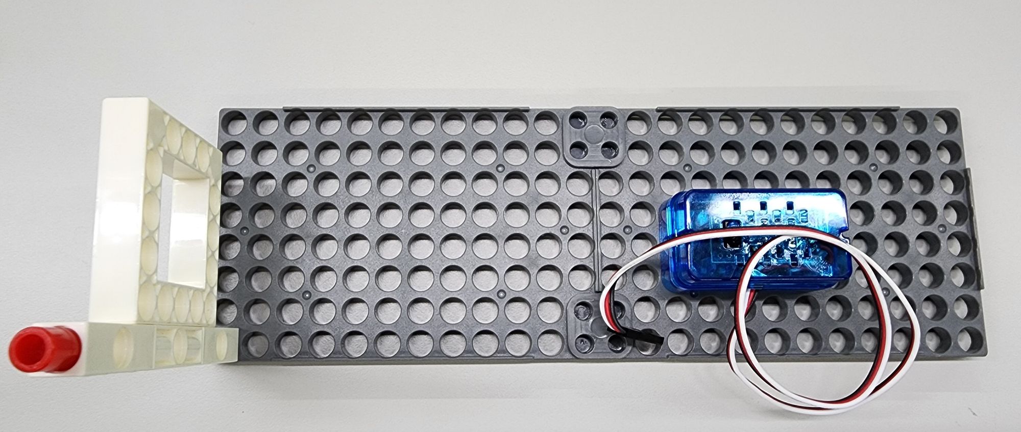
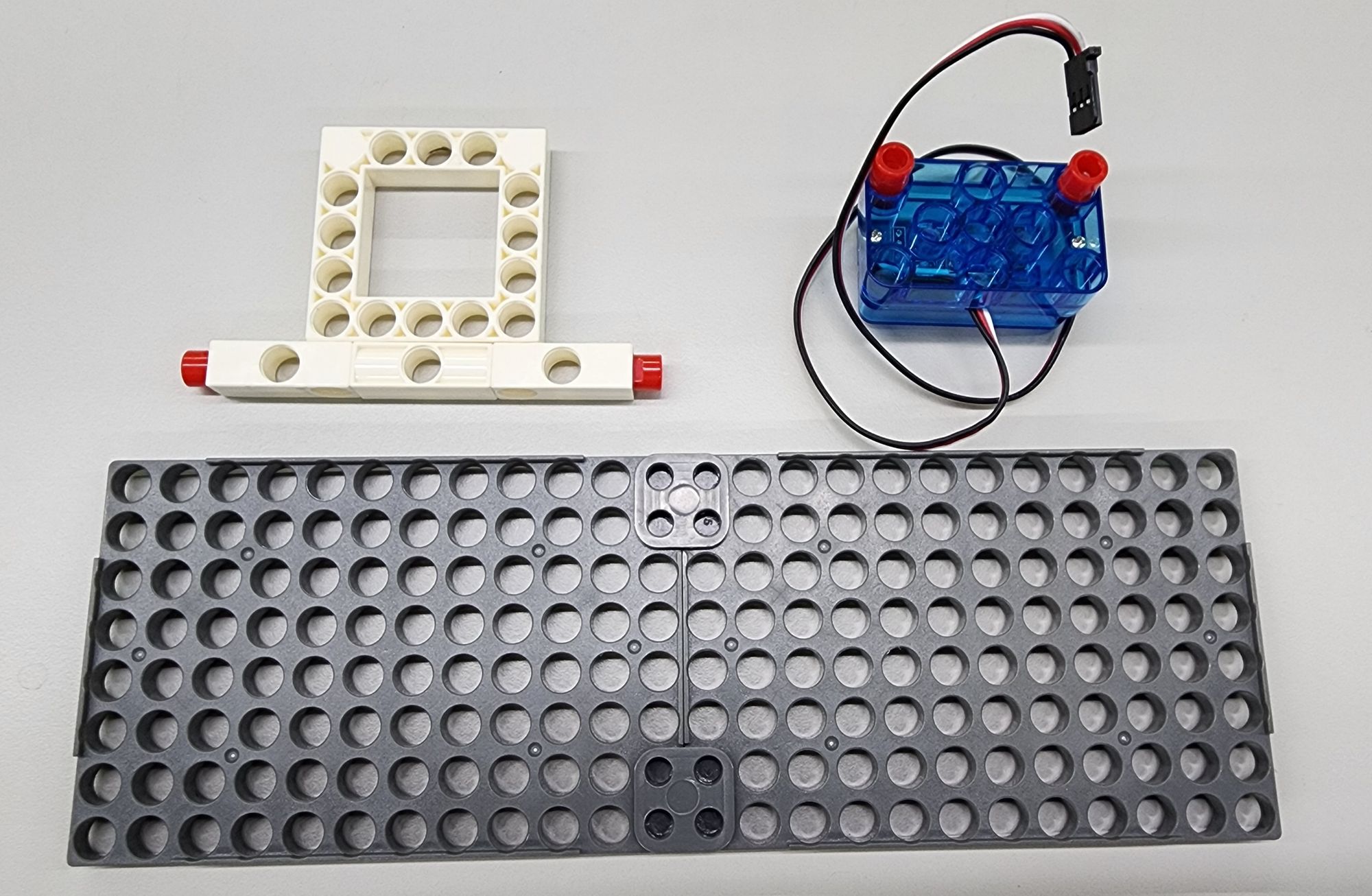
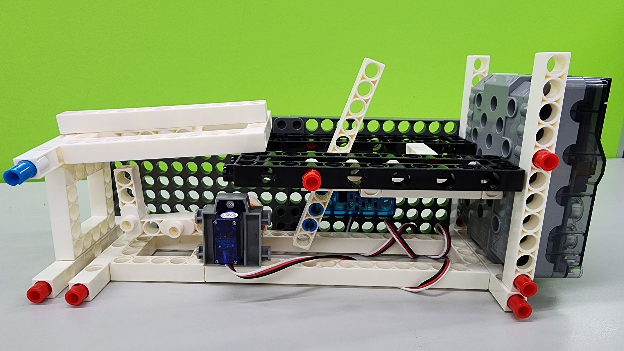
Step 2: The second step is to make the base of the useless box, which will use the C-LONG PEG, C-5X5 FRAME, C-3 HOLE DUAL ROD, C-3 HOLE ROD FRONT CLOSED, C-5X15 FRAME and C-180° SERVO MOTOR (1247- W85-D1-1) (Figure 4), assemble them according to the picture (Figure 5).
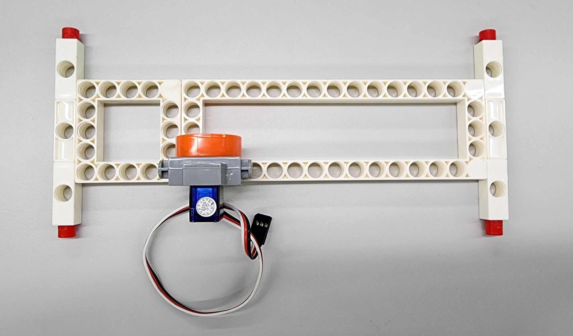
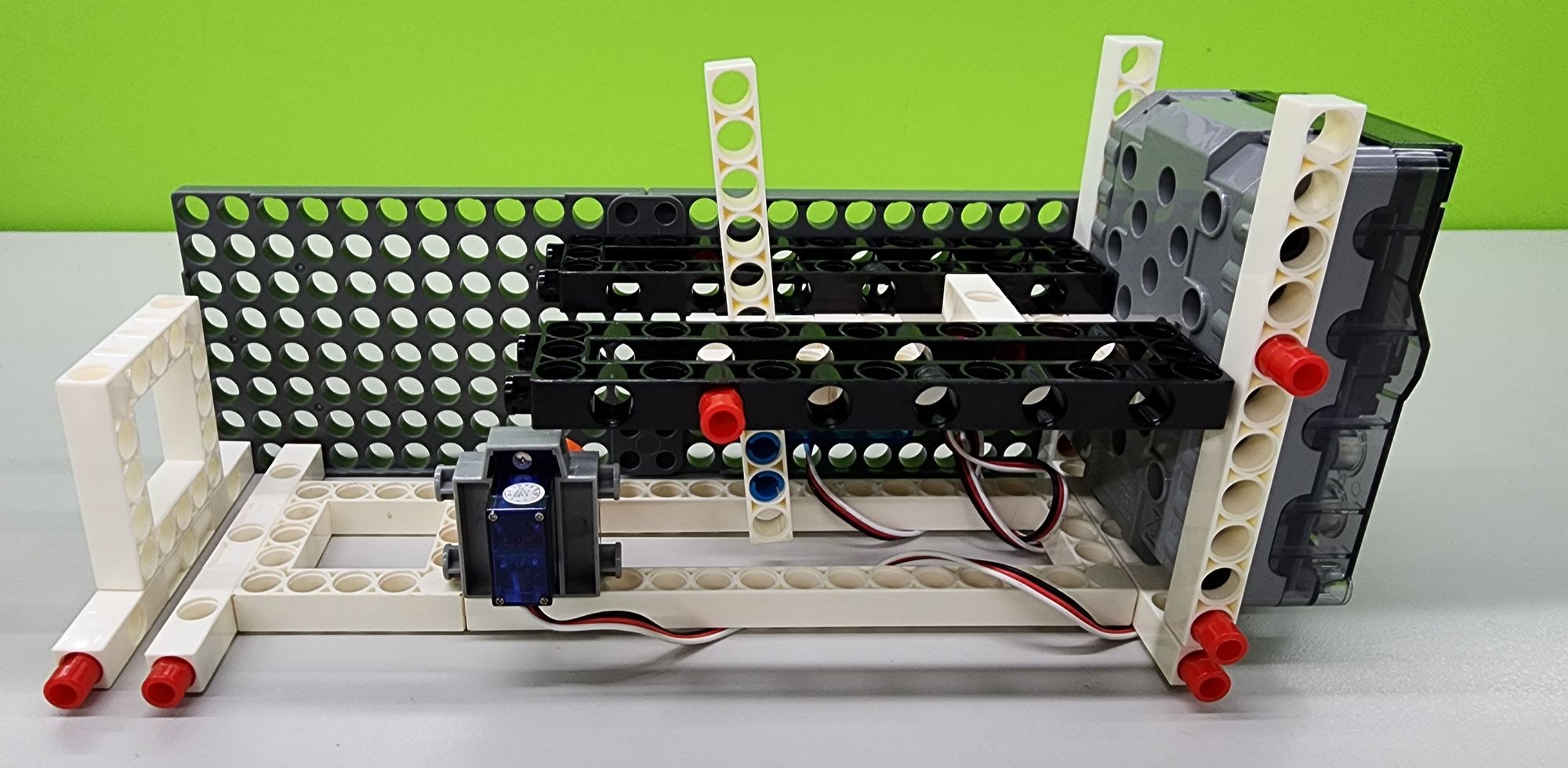
Then we can combine the base with the right baffle to complete the structure of the useless box (Figure 6).
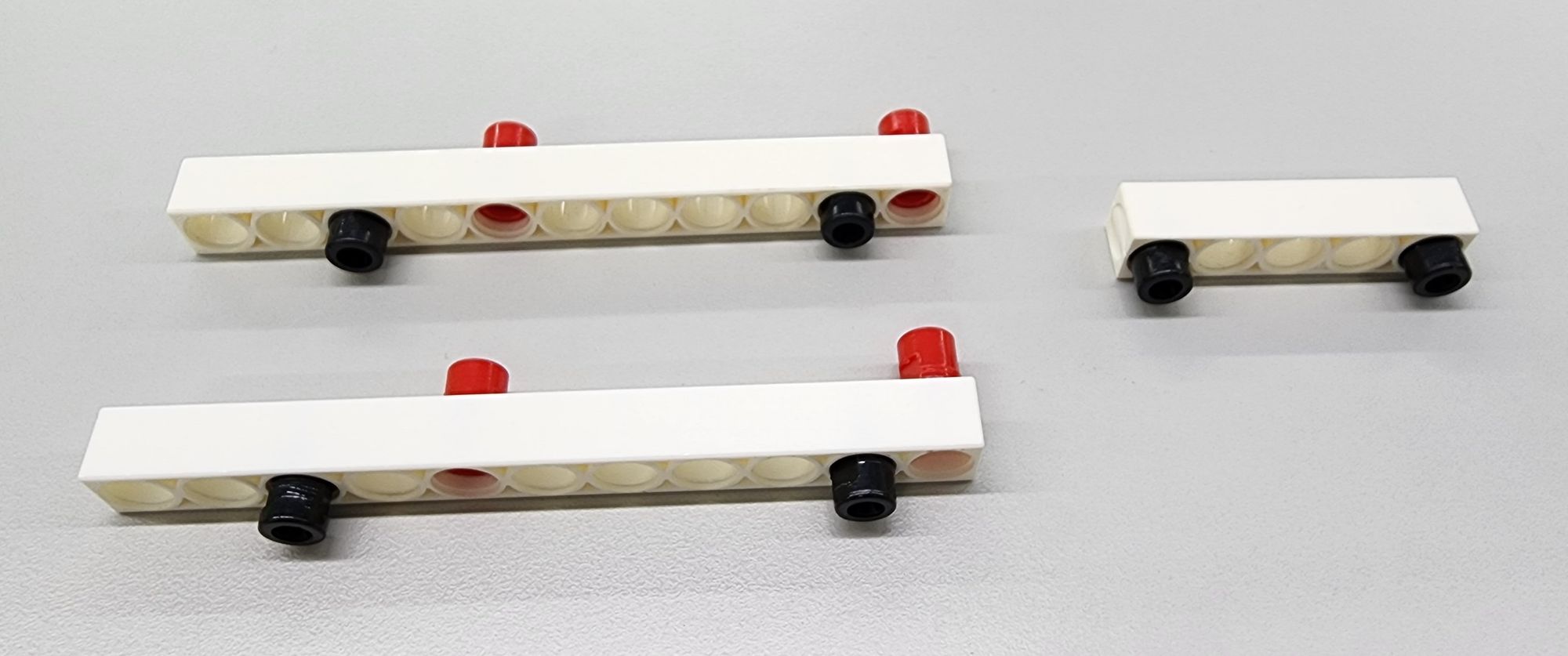
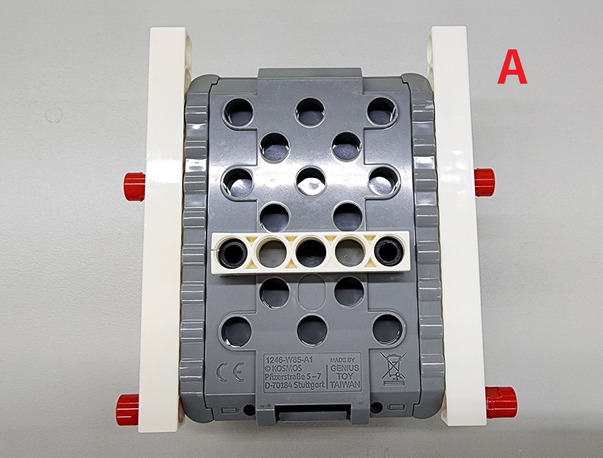
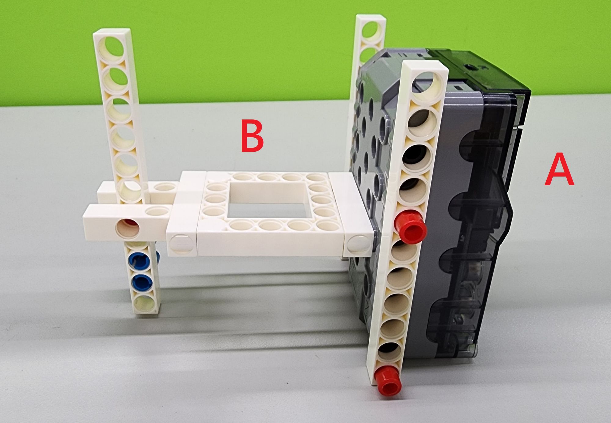
Step 3: We use the C-5 HOLE ROD, the C-11 HOLE ROD, the C-Gigo micro:bit CONTROL BOX (1269-W85-A) and the C-LONG PEG and B-SHORT PEG (Figure 7, Figure 8).
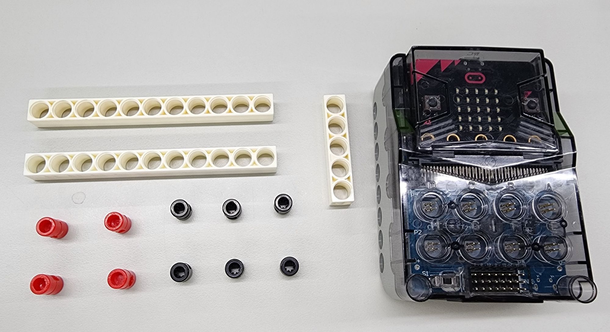
Then combine all components with the C-Gigo micro:bit CONTROL BOX (you need to put the micro:bit board and battery into the main control box in advance), and complete the design of the front baffle (part A) of the useless box (Figure 9). we can first place it aside.
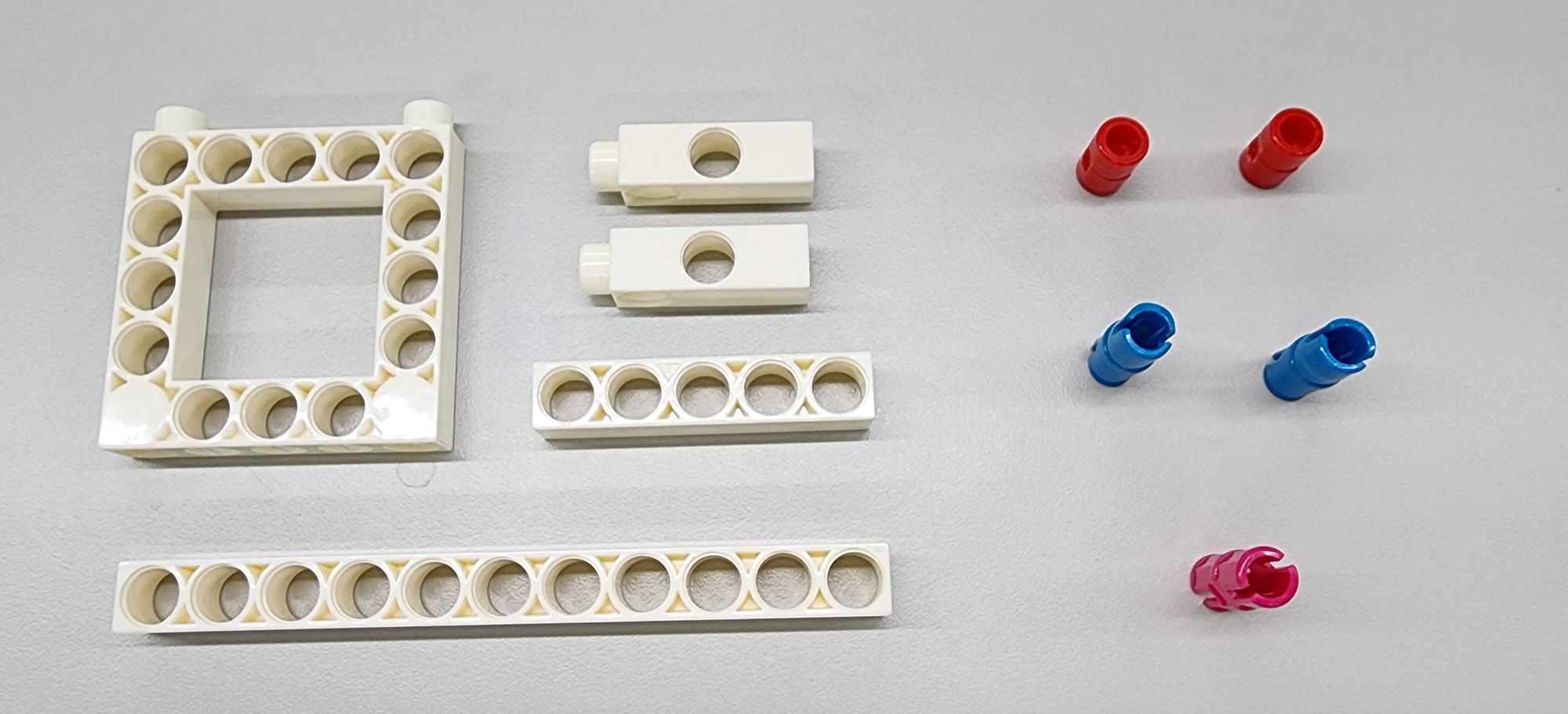
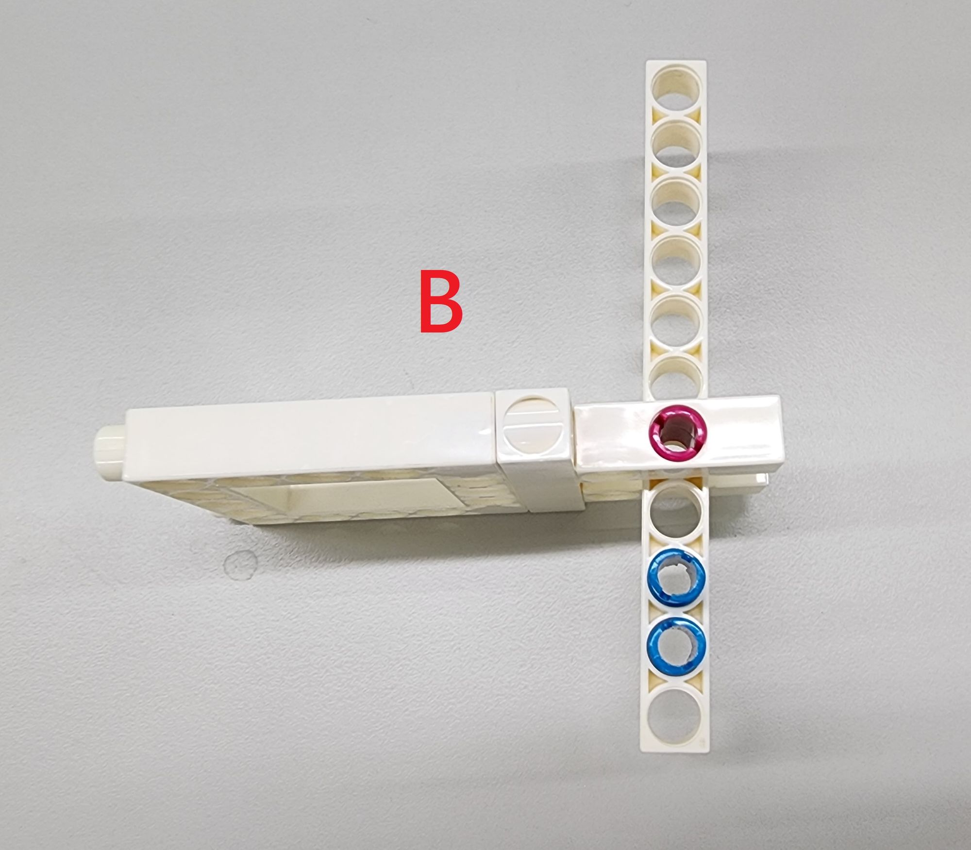
Step 4: We use the C-5X5 FRAME, C-3 HOLE ROD, C-5 HOLE ROD, the C-11 HOLE ROD, C-LONG PEG, C-AXLE CONNECTOR and C-STATIC AXLE CONNECTOR (1187-W10-E1K) (Figure 10). Complete the design of the hammer according to part B as shown (Figure 11).
Next, assemble parts A and B, combine the C-5X5 FRAME of part A with the C-5 HOLE ROD of part B (Figure 12).
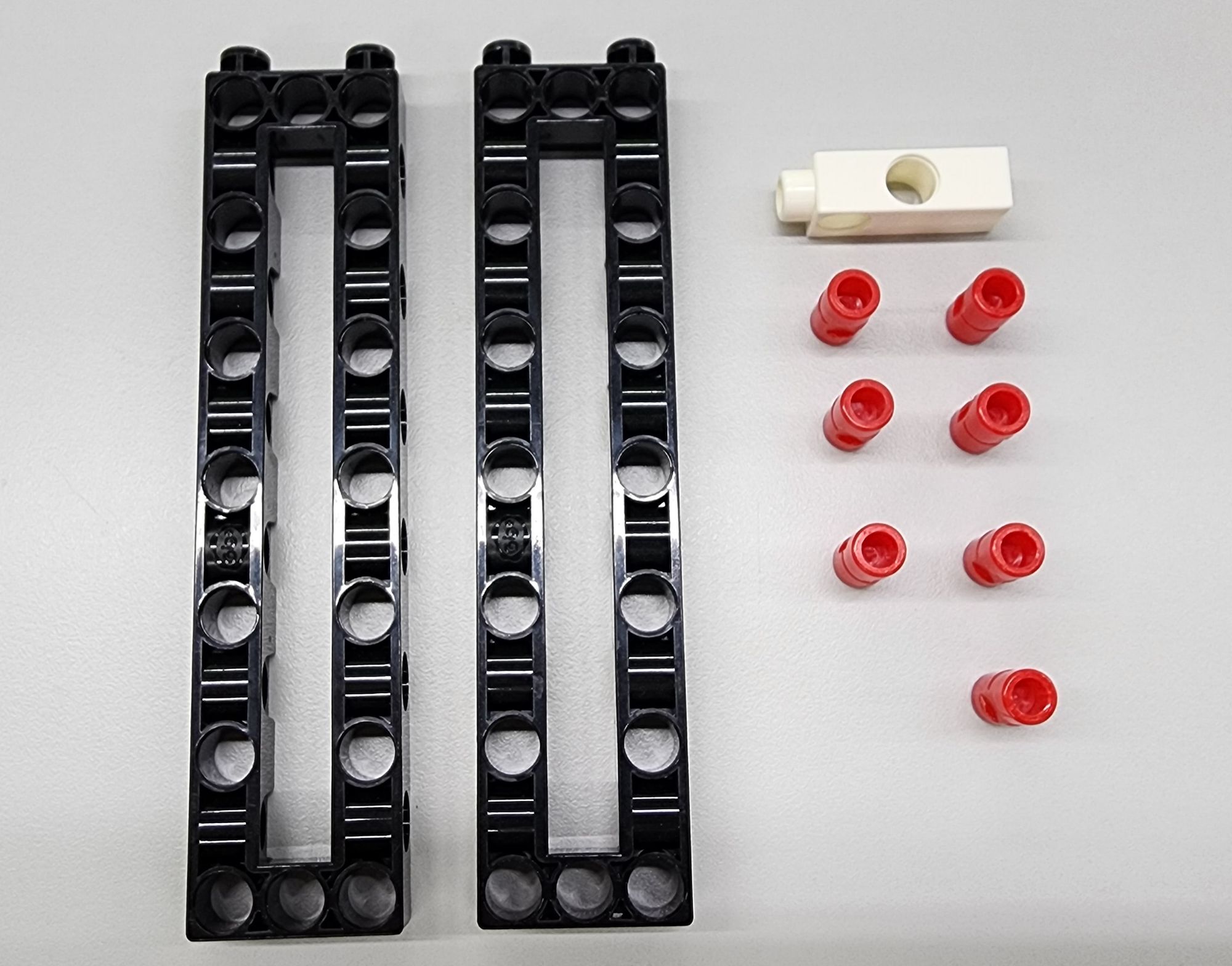
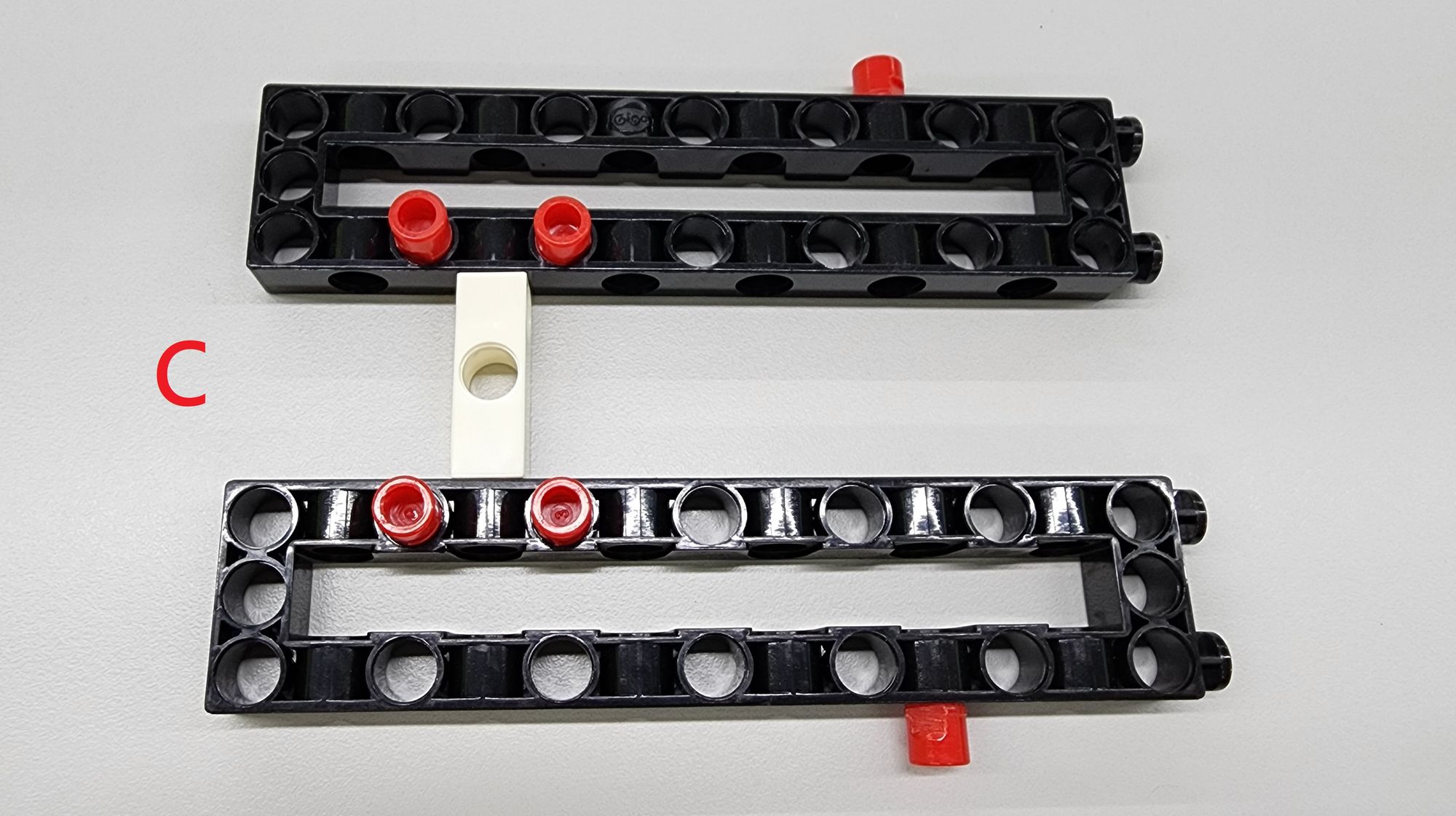
Step 5: Now we reinforce the hammer and the front shield. To do this, we'll use two C-3x13 DUAL FRAME, one C-3 HOLE DUAL ROD, and some C-LONG PEG to assemble them into component C (as shown in Figure 13). This component not only reinforces the structure but also make this box look better.
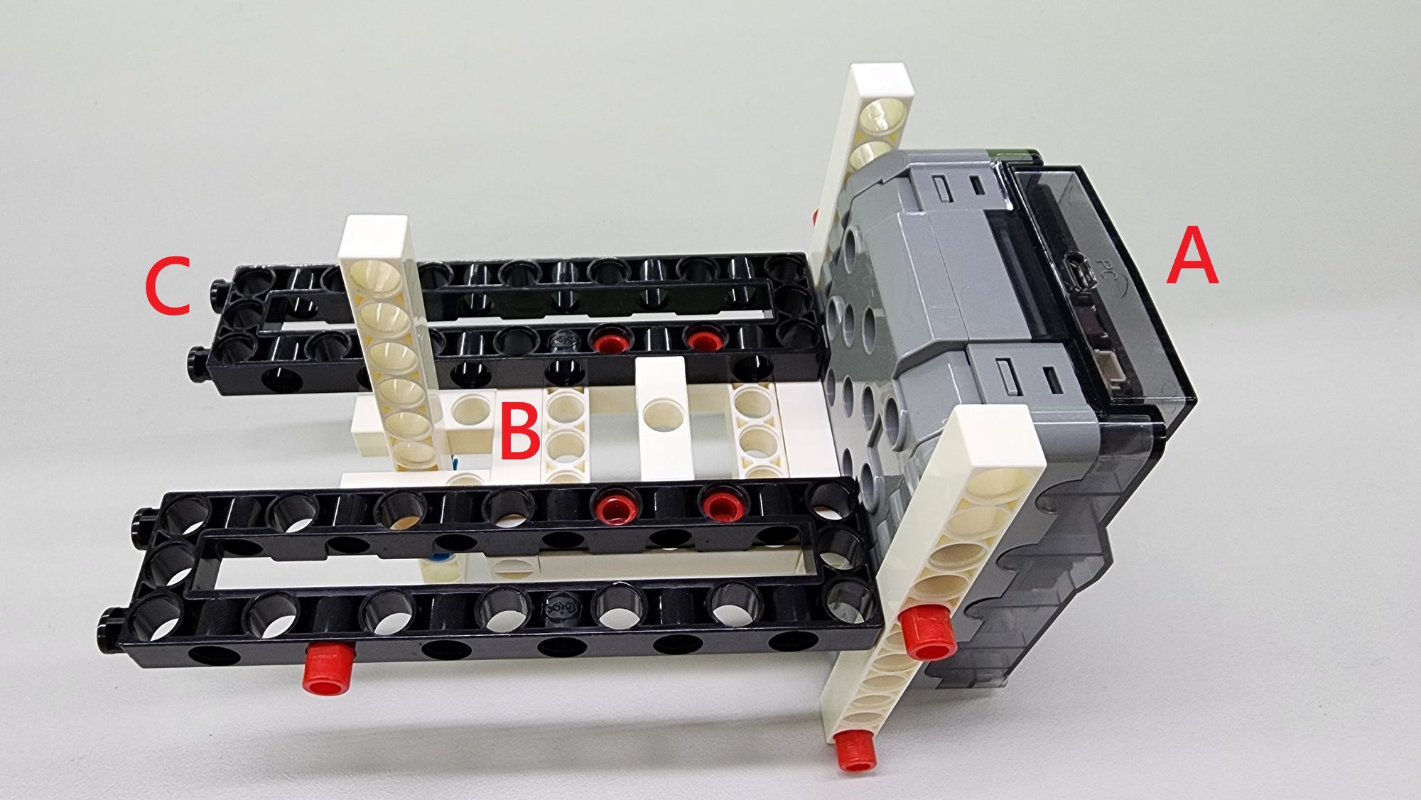
Next, we'll combine component B with component C by attaching the four C-LONG PEG of component C to the C-5X5 FRAME of component B (as shown in Figure 15). Finally, install the completed components A, B, and C on the right shield (as shown in Figure 16).
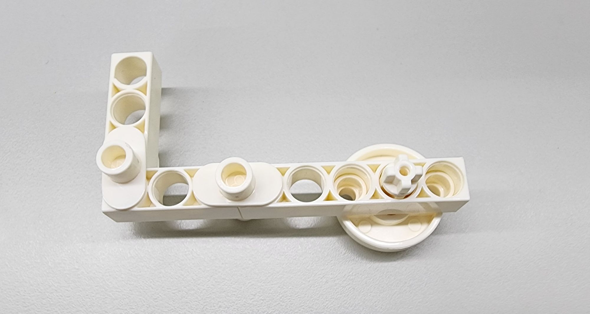
Step 6: we'll make the hammer. This primarily involves using two C-3 HOLE ROD, one C-5 HOLE ROD, one C-ROD CONNECTOR, four C-TWO-IN-ONE CONVERTER, and one C-MOTOR AXLE (as shown in Figure 17). Following the diagram, the completed hammer will have be L-shaped (as shown in Figure 18).
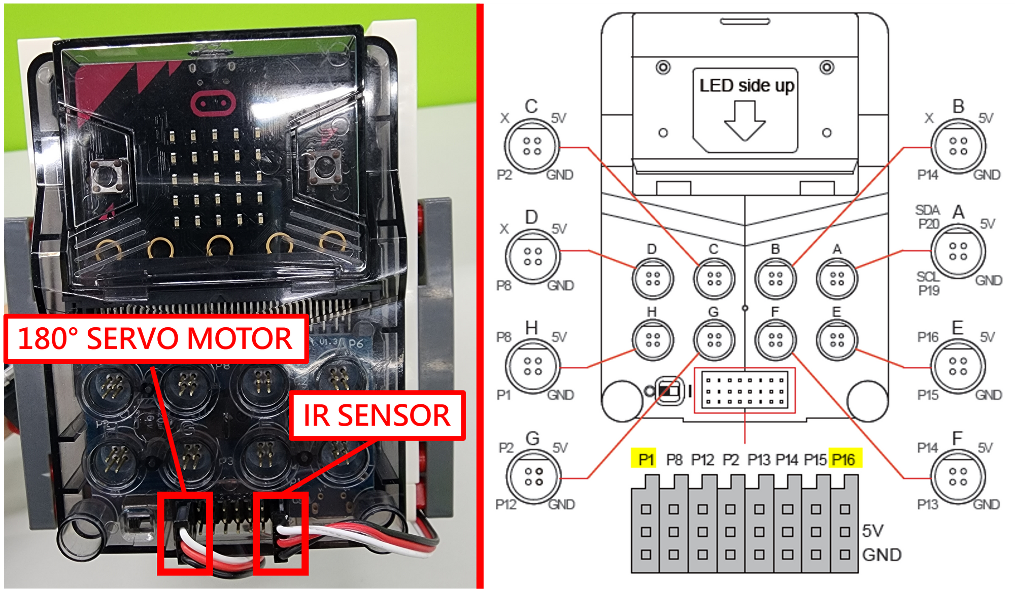
Since the useless box's hammer has a certain range of swinging angle, we need to write the program before assembling the hammer onto the C-180° SERVO MOTOR. First, connect the C-180° SERVO MOTOR and the IR C-LINE FOLLOWER SENSOR's connectors to the micro:bit main control box as shown. The C-180° SERVO MOTOR uses P1, and the IR C-LINE FOLLOWER SENSOR uses P16 (as shown in Figure 19).
Do not manually rotate the C-180° SERVO MOTOR to avoid motor damage.
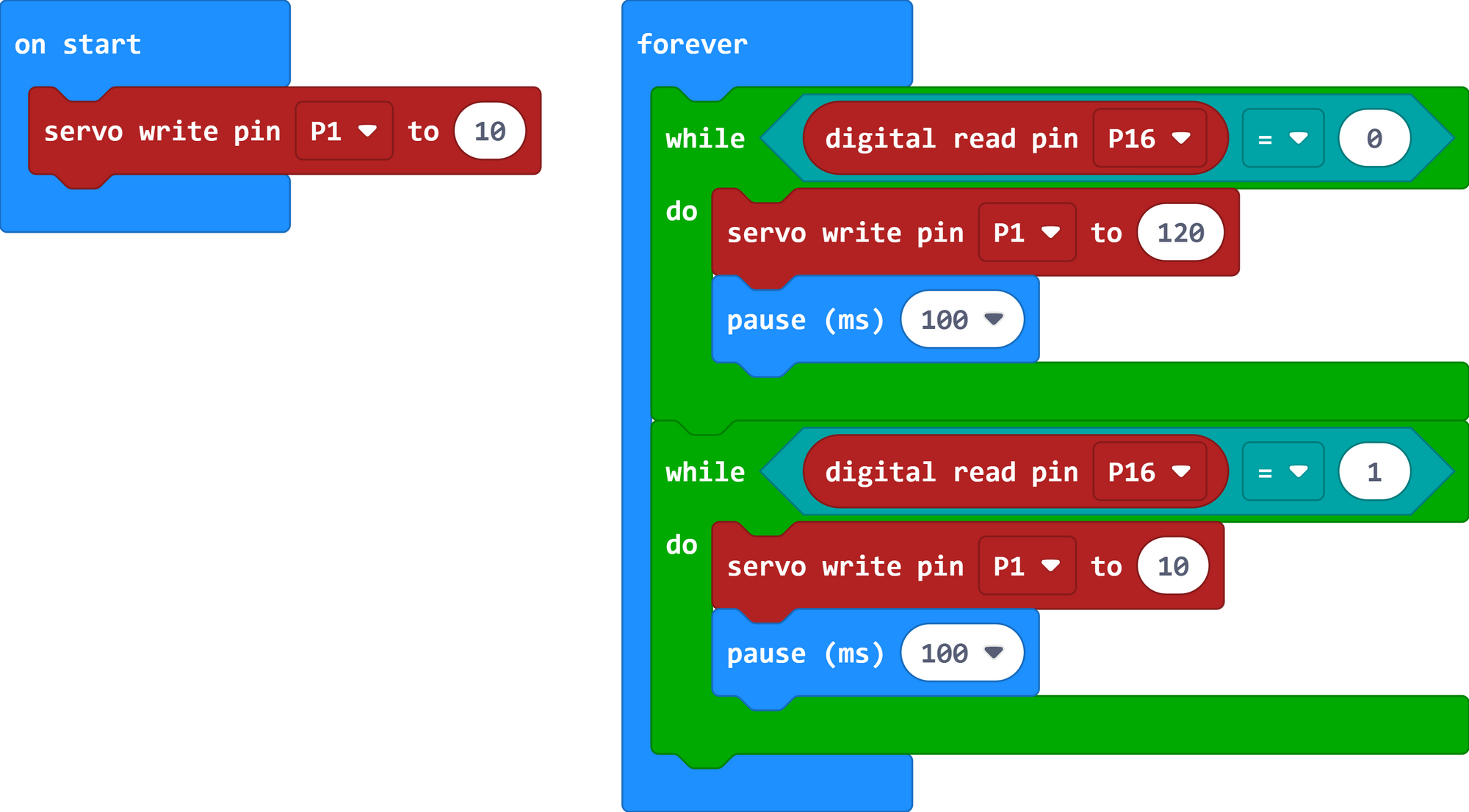
Next, enter the micro:bit program editing webpage and write the following program:
1. When started, fix the angle of the C-180° SERVO MOTOR at 10 degrees.
2. Set a conditional statement (while-do) from Loops, to check when the IR C-LINE FOLLOWER SENSOR detects an object (pin P16 = 0), move the angle of the C-180° SERVO MOTOR to 120 degrees.
3. Set a conditional statement (while-do) from Loops, to check when the IR C-LINE FOLLOWER SENSOR does not detect an object (pin P16 = 1), move the angle of the C-180° SERVO MOTOR to 10 degrees.
Step 7: we'll install the hammer. First, power on the micro:bit main control box, use the program to maintain the angle of the C-180° SERVO MOTOR at 10 degrees, and then install the hammer's 27mm C-MOTOR AXLE on the C-180° SERVO MOTOR at the angle shown (Figure 20). After completing the hammer installation, you can test the box's function by flipping the switch (Video 2).
Once you confirm that it operates smoothly, you can turn off the main control box's power.
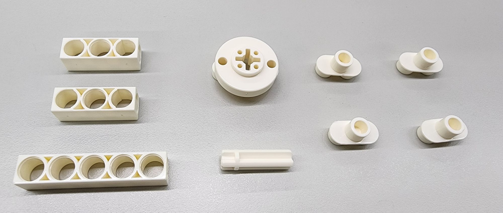
Step 8: we now make the top cover with one C-5X10 FRAME, one C-11 HOLE ROD , two C-3 HOLE DUAL ROD, one C-3 HOLE ROD, one C-3 HOLE ROD FRONT CLOSED, one C-5 HOLE DUAL ROD, C-LONG PEG, and C-AXLE CONNECTOR (as shown in Figure 21). Assemble them according to the following pictures to complete the top cover (Figure22~23).
Next, install the completed top cover on the right shield (Figure24).
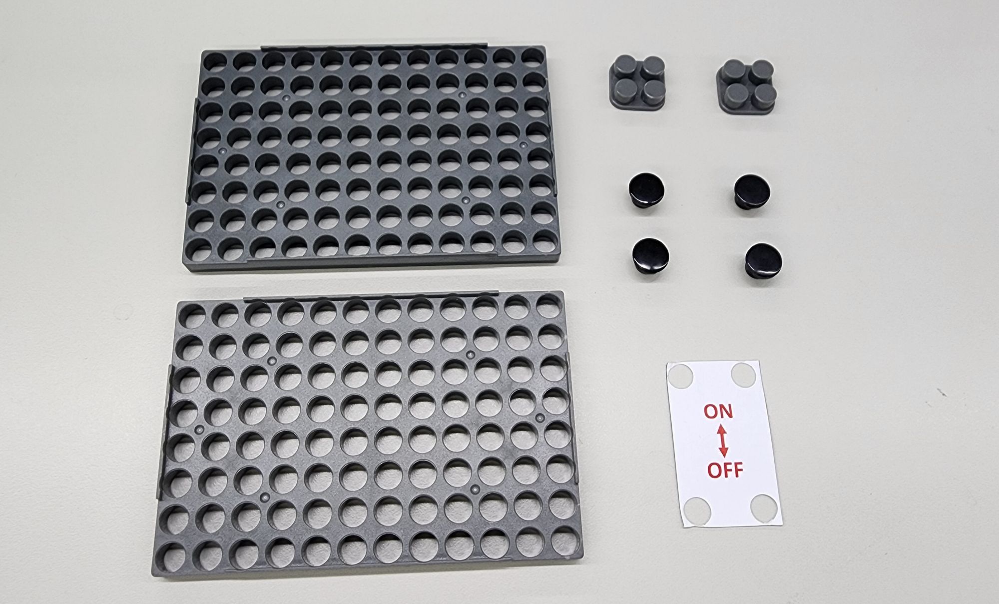
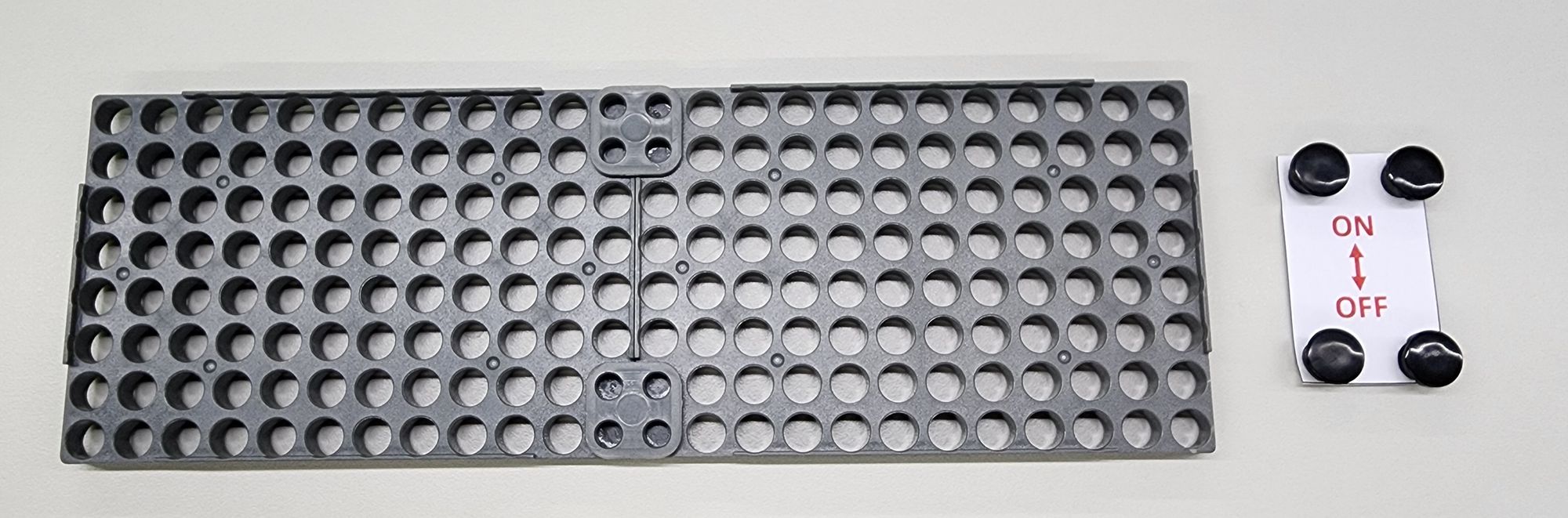
The final step is to make the left shield to enclose the useless box and add the "switch" label. We need to use two 8x12 C-BASE GRID, two C-BASE GRID CONNECTOR, four C-SHORT BUTTON FIXER, and a printed or hand-drawn "switch" label (Figure 25). Assemble them as shown (Figure 26).
Once completed, we can attach them to the useless box. This way, we've created a fun and quirky useless box (Figure 27)!
Now we can try turning on the power, flipping the switch, and challenging the useless box together (Video 3). See who gives up first, you or the useless box? You can also consider it as a fun April Fool's gift for your best friend.
◆Conclusion:
During the process of creating the useless box, we’ve found that building blocks as hardware can provide the possibility of flexibility and fine-tuning. We don't have to replicate the assembly method exactly to make a useless box. We can adjust the position of sensors or the hammer, or modify the shape and appearance of the useless box. After hardware adjustments, software (programming) may also need to be adjusted for optimal performance. Try to create an unique useless box!
Today's sharing ends here. If you like this article, remember to share it with others. See you next time, goodbye!
◆Scientific Principles:
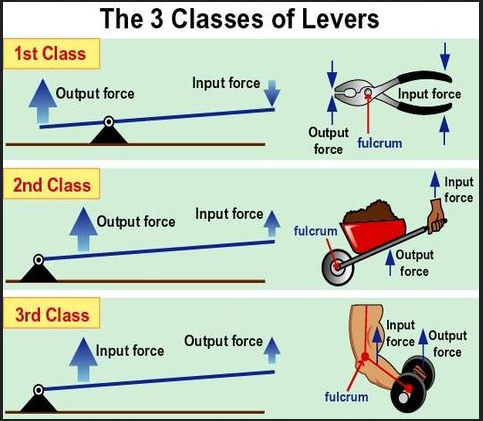
The useless box primarily relies on the scientific principle of leverage and the concept of repetitive conditional statement(while-do) from Loops in the program. Levers can be divided into three classes (Figure 29), and the useless box uses the first-class lever (the fulcrum is between the effort point and the resistance point). This class of lever can change the direction of the object's operation. When we flip the switch, the lever above the fulcrum moves to the left, and the lever below the fulcrum moves to the right. Once it obstructs the IR C-LINE FOLLOWER SENSOR on the right, the program, with its repetitive conditional statement, causes the hammer to rotate upward, flipping the switch back to its original position, thus demonstrating the operation of the useless box (Video 4).
◆Curriculum(NGSS):
3-PS2-1 Plan and conduct an investigation to provide evidence of the effects of balanced and unbalanced forces on the motion of an object.
3-5-ETS1-1 Define a simple design problem reflecting a need or a want that includes specified criteria for success and constraints on materials, time, or cost.
3-5-ETS1-2 Generate and compare multiple possible solutions to a problem based on how well each is likely to meet the criteria and constraints of the problem.
#Gigo #Gigo Lab #Fun Lab #Learning Lab #1269
◆References:
 Contributors to Wikimedia projects
Please sign in to vote.